EP0129021B1 - Wrapping mechanism for bales in a rotobaler - Google Patents
Wrapping mechanism for bales in a rotobaler Download PDFInfo
- Publication number
- EP0129021B1 EP0129021B1 EP19840104553 EP84104553A EP0129021B1 EP 0129021 B1 EP0129021 B1 EP 0129021B1 EP 19840104553 EP19840104553 EP 19840104553 EP 84104553 A EP84104553 A EP 84104553A EP 0129021 B1 EP0129021 B1 EP 0129021B1
- Authority
- EP
- European Patent Office
- Prior art keywords
- cutting
- wrapping
- web
- wrapping material
- operating lever
- Prior art date
- Legal status (The legal status is an assumption and is not a legal conclusion. Google has not performed a legal analysis and makes no representation as to the accuracy of the status listed.)
- Expired
Links
Images


Classifications
-
- A—HUMAN NECESSITIES
- A01—AGRICULTURE; FORESTRY; ANIMAL HUSBANDRY; HUNTING; TRAPPING; FISHING
- A01F—PROCESSING OF HARVESTED PRODUCE; HAY OR STRAW PRESSES; DEVICES FOR STORING AGRICULTURAL OR HORTICULTURAL PRODUCE
- A01F15/00—Baling presses for straw, hay or the like
- A01F15/07—Rotobalers, i.e. machines for forming cylindrical bales by winding and pressing
- A01F15/071—Wrapping devices
- A01F15/0715—Wrapping the bale in the press chamber before opening said chamber
-
- Y—GENERAL TAGGING OF NEW TECHNOLOGICAL DEVELOPMENTS; GENERAL TAGGING OF CROSS-SECTIONAL TECHNOLOGIES SPANNING OVER SEVERAL SECTIONS OF THE IPC; TECHNICAL SUBJECTS COVERED BY FORMER USPC CROSS-REFERENCE ART COLLECTIONS [XRACs] AND DIGESTS
- Y10—TECHNICAL SUBJECTS COVERED BY FORMER USPC
- Y10T—TECHNICAL SUBJECTS COVERED BY FORMER US CLASSIFICATION
- Y10T83/00—Cutting
- Y10T83/869—Means to drive or to guide tool
- Y10T83/8776—Constantly urged tool or tool support [e.g., spring biased]
- Y10T83/8782—Stored energy furnishes cutting force
Definitions
- the invention relates to a device that can be attached to a baler for wrapping a round bale from agricultural crop material contained in the forming chamber of the baler with a section of an enveloping web, according to the preamble of claim 1.
- a drive which can be switched on and off is provided for one of the two pull-off rollers of the pull-off device, which is derived from a motor, from a towing vehicle pulling the baler or from another drive device, and comprises a chain drive.
- a belt drive is provided instead of the chain drive, the drive belt of which can be brought into drive transmission engagement with the belt pulleys of the belt drive by a pressure roller carried by a first pivoting control lever and can be deactivated by triggering the pressure engagement of the pressure roller on the V-belt.
- the cutting member consists of an elongated, one-piece knife with an approximately central tip of the envelope, which is attached to a displaceably guided carrier. Acting against the two directions of displacement of the carrier, effective compression springs act on the carrier, which prescribe a rest position for the carrier and with it the cutting element, in which the cutting element is at a distance above the enveloping path plane which the enveloping path occupies in the cutting area during a wrapping process. By means of a second pivot control lever, the cutting member can be lowered against the action of the first group of springs into a cutting end position in which the cutting knife passes through the plane of the enveloping path.
- an operator actuates the first pivoting operating lever in order to switch on the drive for the take-off rollers of the take-off device and to pull off a piece of enveloping web from the supply roller and to feed the material inlet opening to the molding chamber.
- the drive on the take-off rollers can be switched off by returning the first pivoting operating lever to its initial position.
- the wrapping sheet Due to the fact that the wrapping sheet is entrained by the round bale, which usually executes a rotational movement about its longitudinal central axis during the wrapping process with the aid of conveying elements that are effective in the molding space, the wrapping of the round bale takes place by progressive wrapping in the wrapping sheet until a desired degree of wrapping is achieved. This is generally at least about 390 ° wrap angle, but can also e.g. B. 720 ° or 900 ° wrap angle. In the latter cases, the degree of wrapping, without gluing the overlapping winding areas of the wrapping web, ensures that the wrapping web remains firmly on the outer circumference of the round bale when it is ejected from the molding chamber and deposited on the field.
- the wrapping process can be ended by actuating the second pivoting operating lever and cutting the wrapping sheet along with it, the wrapping process.
- the invention has for its object to provide a device of the type specified in the preamble of claim 1, which can be put into operation by actuating a single swivel control lever and automatically ends the wrapping process when a predetermined wrapping degree is reached.
- the device according to the invention enables simple single-lever operation, the wrapping process only having to be started by actuating the pivoting operating lever.
- a measuring process takes place, by means of which a predetermined degree of wrapping for the round bale can be determined and at the end of which the web section enveloping the round bale is automatically cut off from the wrapping web on the supply roll.
- the device With the automatic completion of the wrapping process, the device at the same time returns to a starting position for wrapping a subsequent round bale by actuating the single swivel control lever again. Simultaneously with the simplification of the operation, there is also an increased accuracy of the wrapping, since all bales are wrapped in the wrapping web independently of being observed by an operator with the same degree of wrapping.
- the design of the device according to the invention enables a particularly simple retrofitting of balers with such a device without any noteworthy modification work on the baler and with minimal assembly effort.
- the balers can already be manufactured by the manufacturer without any noteworthy information Additional expenditure for such a later retrofit must be prepared.
- the special design of the cutting element ensures quick and particularly clean cutting of all types of wrapping materials, including mesh-like or lattice-shaped web materials, since the entire area of the cutting line is cut by a real cutting process, which also takes place so quickly that fraying occurs caused by tears due to a non-uniform, simultaneous overall cut.
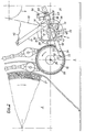
- Fig. 1 illustrates a baler 1 with a molding chamber 2, a crop receiving device 3 in the direction of travel 4 in front of and below a crop entry opening 5 to the molding chamber 2, and conveying elements 6, which transport the harvested crop into the molding chamber 2 up to the completion of the molding process for the to form round bales.
- Balers of this type are known for themselves. Their special design is not important for the wrapping device according to the invention, which can also be connected to balers of a construction other than that shown.
- the wrapping device is designated in its entirety by 7 and, in the installed position on the baler 1, has a position in front of and relatively close above the material entry opening 5. It forms an overall assembly that can be subsequently inserted into the front area of the press housing 8.
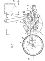
- the wrapping device 7 comprises a supply roll 9 of an endless wrapping web 10 and a take-off device 11 in the form of two take-off rolls 12, 13 which are in constant mutual pressure engagement and which are driven promote the envelope between them together towards the good entry opening. Furthermore, the wrapping device comprises a drive device 14 for the trigger device 11, specifically in the form of a friction gear with two friction wheels 15, 16, which can be moved in and out of mutual frictional engagement by means of a pivoting control lever 17.
- the wrapping device comprises a cutting device 18 which can be actuated towards the end of the wrapping process and which has a cutting element 20 which can be moved transversely to the direction of travel 19 of the wrapping web 10 from its starting cutting position illustrated in FIG , which is arranged in the region between the material inlet opening 5 and the extraction device 11 and is fastened to a carrier 21, on which springs 22 engage.
- the first friction wheel 15 of the friction wheel transmission 14 is fastened on one end of a drive shaft 23 for the conveying elements 6 of the molding chamber 2 of the baling press 1.
- the associated end of the drive shaft 23 is supported in a bearing 24 in a first wall 25 of the press housing 8 and carries the friction wheel 15 on a part 26 projecting outwards beyond the bearing 24.
- the friction wheel 15 rotates continuously with the drive shaft 23 if, for example, during the bale forming process and during the wrapping process. is driven by the towing vehicle for the baler 1.
- one full revolution of the drive shaft 23 and thus of the friction wheel 15 corresponds to an angle of rotation for the round bale 27 or a circumferential angle which, depending on the design of the baler, is, for. B. corresponds to an eighth of the total circumferential angle of 360 °.
- the second friction wheel 16 of the friction gear 14 is fixedly attached to the shaft end of the shaft 12 'of the pull-off roller 12 of the pull-off device 11 and can be pressed from its starting position according to FIG. 2 apart from frictional engagement with the friction wheel 15 in frictional engagement on the friction edge 15.
- the first friction wheel 15 has on its circumference a lining 28 which increases the friction factor, e.g. made of rubber, plastic or the like, and the friction wheel 16 has e.g. a corrugation not illustrated in detail.
- the first friction wheel 15 is assigned a cantilevered, measurable measuring element 29, which in a particularly simple embodiment is designed as a threaded bolt, the threads of which form a measuring section.
- the threaded bolt 29 is in one in the end 26 of the drive shaft 23 coaxially arranged blind threaded bore 30 can be screwed in and fixed in its respective screw-in position by means of a lock nut 31.
- the screw-in position is determined in view of a desired degree of wrapping of the round bale 27 by the wrapping web 10, in such a way that, for example with a wrapping degree of 720 ° wrap angle, the projecting end of the threaded bolt 29 16 full, freely palpable threads in the area between the lock nut 31 and the Provides the outer end of the threaded bolt 29.
- 16 full revolutions of the drive shaft 23 and thus of the threaded bolt 29 correspond to two full revolutions of the round bale 27.
- the shaft ends of the shaft 12 'of the take-off roller 12 are supported in bearings by end bearing plates 32, 33, and the bearing plates 32, 33 are connected to one another via axially parallel connecting means to form a structural unit.
- a sheet metal angle profile 34 can be used as the connecting means, the z. B. with mutually facing inner sides of the bearing plates 32, 33 (not shown in Fig. 5 for reasons of clarity).
- the swivel control lever 17 engages on a swivel shaft 35 which is also mounted in the two bearing plates 32, 33, axially parallel to the take-off rollers 12, 13 and which also serves as a bearing axis for swivel bracket 36 which is freely pivotably mounted on it.
- These swivel brackets 36 support the second pull-off roller 13 via shaft bearings, which can accordingly be moved in a swivel movement about the central axis 37 of the swivel shaft 35 against the pull-off roller 12 in pressure engagement.
- the tension springs 22 serve to bring about constant pressure engagement, the ends of which, opposite the carrier 21 for the cutting member 20, engage the swivel brackets 36.
- the take-off roller 13 is freely rotatably mounted in its shaft bearings on the swivel brackets 36 and receives its rotational movement from the take-off roller 12 as a result of the pressure intervention via the envelope web 10 arranged between the two take-off rollers 12, 13.
- the assembly comprising the bearing plates 32, 33, their connecting means 34 and the parts carried by the bearing plates 32, 33 can be inserted into the wall 25 of the press housing 8 through an insertion opening 38 in the manner of an insert.
- the bearing plate 33 of the structural unit facing away from the friction gear 14 can be firmly connected to an associated second wall 25 'of the press housing 8 of the baling press 1, while the bearing plate 32 facing the friction gear 14 is supported in the insertion opening 38 so as to be horizontally displaceable to a limited extent.
- the insertion opening 38 is at least in the horizontal direction somewhat wider than the bearing plate 32 in this direction, in order to make it possible for the bearing plate 32 to be displaceable from the initial position according to FIG. 2 to the position according to FIG.
- a spring 39 engages on the bearing plate 32 on the side facing away from the friction wheel 15 and serves to hold the bearing plate 32 in its starting position according to FIG. 2 or after a displacement movement in the direction of the friction wheel 15 back into the starting position according to FIG 2 to move back.
- the spring 39 engages with its other end on a pin 40 on the wall 25 of the press housing.
- the carrier 21 for the cutting member 20 is formed by a carrier strip 21 which extends approximately over the width of the enveloping web 10 and parallel to the take-off rollers 12, 13 and on which cranked lever arms 41 which act on the pivot shaft 35 of the pivot control lever 17 and which engage the drive shafts of the take-off rollers 12, 13 overlap.
- the cutting member 20 receives its orientation, as can be seen in particular in FIGS. 2 to 4.
- the cutting member consists of a plurality of approximately triangular knife blades arranged in two rows and fastened next to one another on the carrier strip 21, of which the knife blades arranged in the first row with 42 and those in the second row are designated by 43.
- the knife blades 42 of the first row are arranged at a distance parallel to the surface and offset from the knife blades 43 of the second row, in such a way that the knife blades 42, 43 point with a triangular tip to the enveloping web 10 and - seen in front view - the sharpened cutting edges 44 of the blades 43 of the second row intersect with the cutting edges 44 of the blades 42 of the first row in points that form approximately cutting edge bisection points.
- the distance between the knife blades 42 of the first row and the knife blades 43 of the second row is determined in the exemplary embodiment shown by the thickness of the carrier strip 21, on the rear or front side of which the first and the second row of the knife blades 42, 43 are screwed.
- This special design of the cutting member enables a clean cutting cut, which simultaneously covers the entire width of an enveloping web 10, even when the enveloping web is e.g. has a net or lattice structure.
- the swivel control lever 17, at the upper end of which a pull cord 45 can engage, is firmly connected at its lower end to a lever arm 46, which in turn is connected to a connecting bush 47 on the end of the swivel shaft 35.
- the lever arm 46 At the end facing away from the bushing 47, the lever arm 46 is connected to an angle arm 48, which carries a probe arm 50 on the outside of its leg 49, which is advanced over the plane of the friction gear mechanism 14.
- This probe arm 50 extends into the central region of the friction wheel 15 and is designed as a spring lamella that is only flexible in the transverse direction.
- the probe arm carries at its free end 50 a swivel locking pawl 51 which is fastened to the sensing arm 50 to a limited extent by means of an articulated bolt 52.
- the probe arm 50 has an arcuate limiting slot 53 into which a stop pin 54 engages the pawl 51.
- the arrangement is selected such that when the probe arm 50 moves upward, the pivoting locking pawl 51 can swing out of its locking position, which it assumes in FIGS. 2 and 4, counterclockwise when it hits the measuring member 29 and, after passing through the measuring member 29 in their locking position falls back. If, in the locking position of the swivel locking pawl, it rests on the measuring element 29, it engages with a lower sensing edge 55 in the thread, i.e. the measuring section, of the measuring element 29, while at the same time preventing the sensing arm 50 from moving out of its position in FIG. 4 to return to the starting position according to FIG. 2.
- an angle piece 56 is attached to the wall 25 of the press housing 8, which carries an adjustable stop 57 for the swivel control lever 17.
- This stop 57 forms a thrust abutment on which the pivot control lever 17 bears shortly before reaching its actuation end position, with the result that a continuous pivoting movement of the pivot control lever 17 (in e.g. FIG. 4 clockwise) leads to the entire end on the lever side the assembly and thus the friction wheel 16 is moved in the direction of the friction wheel 15 and the two friction wheels 15, 16 come into drive-transmitting friction.
- an adjustable stop 58 is provided on the lever part 48, which, in engagement with the angle piece 56, limits the starting position of the pivoting operating lever 17 (FIG. 2) and at the same time prevents the assembly from shifting in the direction of the friction wheel 15.
- the above-described wrapping device works as follows: If a round bale 27 has been completed in the molding chamber 2, the pivoting operating lever 17 in FIG. 2 is actuated clockwise starting from the starting position of all parts of the wrapping device 7 illustrated in FIG. 2, e.g. by pulling on the towing line 45. As a result, the device is brought into the state according to FIG. 3. In the position of the parts according to FIG. 3, the swivel control lever 17 has reached its final actuation position, which is defined by the application of the friction wheel 16 on the friction wheel 15.
- This application is brought about by a sliding movement of the bearing plate 32 in the direction of the friction wheel 15 in the insertion opening 38, which is caused by the thrust effect of the swivel control lever 17 resting on the thrust abutment 57.
- the swivel control lever 17 was transferred from its initial position in FIG. 2 to its final actuation position according to FIG. 3, by pivoting the swivel shaft 35, the cutting member 20 of the cutting device 18 has undergone a swivel displacement from its rest position according to FIG. 1 into an end position, which is approximately the later cutting starting position corresponds.
- the tension springs 22 which were already tensioned in the rest position of the cutting member 20 according to FIG.
- the take-off device 11 receives its drive from the friction gear 14, which is maintained until the leading end of the enveloping web 10, which is conveyed by the take-off rollers 12, 13, has reached the material inlet opening 5 and further into the molding chamber and there is now taken from the round bale 27 itself.
- the operator stops pulling on the pull line 45, whereby the parts assume their position as illustrated in FIG. 4 due to the pulling action of the tension springs 22 and also of the tension springs 39.
- the swivel locking pawl 51 rests with its lower contact edge 55 on the threaded bolt 29, with the result that the feeler arm 50 and by this the swivel control lever 17, the swivel shaft 35 and the cutting member 20 are locked in a position which is the starting position for cutting the cutting member 20 corresponds.
- the drive engagement between the friction wheels 15, 16 is interrupted, while together with the drive shaft 23 for the conveying elements 6, the friction wheel 15 and the threaded bolt 29 continue to rotate.
- the swivel locking pawl 51 scans the threads of the threaded bolt 29, as a result of which (FIG. 5) the probe arm 50 progressively bends out until the end of the threaded bolt 29 the swivel locking pawl 51 is released from the last thread turn and allows the probe arm 50 to drop back into the starting position according to FIG. 2. 4, and the cutting element 20 moves under the action of the tension springs 22 in a sudden cutting movement, which is reinforced by the weight of the parts, into the cutting end position according to FIG. 2, severing the envelope on the way.
- the wrapping process is thus completed and the wrapping device is again in its starting position according to FIG. 2, in which it is ready for the execution of a new wrapping process.
- the conveyor drive for the round bale 27 can now be interrupted and the wrapped round bale 27 ejected by opening the molding chamber 2 and placed on the floor.
- the above-described wrapping device is structurally extremely simple and is particularly well suited to the rough agricultural operation. This also applies in particular to the parts 29, 51 etc. which form the measuring and triggering device on the one hand and the locking device for locking the cutting member 20 in its starting position.
- a suitable measuring and triggering device e.g. one that does not determine the degree of cladding depending on the path of the conveying elements 6, but e.g. directly measures the length of a peeled web part and then triggers the locking of the cutting member 20 when a predetermined measuring length is reached.
- the locking device formed by the parts 50, 51 instead of the locking device formed by the parts 50, 51 to provide another z. B. acts on the carrier 21 or its pivot arms 41 and comprises a locking body which is then actuated by the measuring and triggering device.
Landscapes
- Life Sciences & Earth Sciences (AREA)
- Environmental Sciences (AREA)
- Storage Of Harvested Produce (AREA)
- Preliminary Treatment Of Fibers (AREA)
- Auxiliary Devices For And Details Of Packaging Control (AREA)
Abstract
Description
Die Erfindung bezieht sich auf eine an eine Ballenpresse anbaubare Vorrichtung zum Umhüllen eines in der Formkammer der Ballenpresse enthaltenen Rundballens aus landwirtschaftlichem Erntegut mit einem Abschnitt einer Hüllbahn, gemäss dem Oberbegriff des Anspruchs 1.The invention relates to a device that can be attached to a baler for wrapping a round bale from agricultural crop material contained in the forming chamber of the baler with a section of an enveloping web, according to the preamble of claim 1.
Bei einer bekannten Vorrichtung dieser Art (DE-PS 2 930 590) ist ein ein- und abschaltbarer Antrieb für eine der beiden Abzugsrollen der Abzugsvorrichtung vorgesehen, der von einem Motor, von einem die Ballenpresse ziehenden Zugfahrzeug oder von einer anderen Antriebsvorrichtung her abgeleitet ist und einen Kettentrieb umfasst. Bei in der Praxis ausgeführten Umhüllungsvorrichtungen dieser Art ist anstelle des Kettentriebs ein Riementrieb vorgesehen, dessen Treibriemen durch eine von einem ersten Schwenkbedienungshebel getragenen Druckrolle in Antriebsübertragungseingriff mit den Riemenscheiben des Riementriebs überführt und durch Auslösen des Druckeingriffs der Druckrolle auf den Keilriemen ausser Antriebsfunktion gesetzt werden kann. Das Schneidorgan besteht aus einem langgestreckten, mit einer etwa mittigen Spitze der Hüllbahn zugewandten einteiligen Messer, das an einem verschieblich geführten Träger angebracht ist. Auf den Träger wirken dabei entgegen beiden Verschieberichtungen des Trägers wirksame Druckfedern ein, die dem Träger und mit diesem dem Schneidorgan eine Ruhelage vorgeben, in der sich das Schneidorgan im Abstand oberhalb der Hüllbahnebene befindet, welche die Hüllbahn während eines Umhüllungsvorgangs im Schneidbereich einnimmt. Mittels eines zweiten Schwenkbedienungshebels ist das Schneidorgan entgegen der Wirkung der ersten Gruppe von Federn in eine Schneidendstellung absenkbar, in der das Schneidmesser die Ebene der Hüllbahn durchgreift.In a known device of this type (DE-PS 2 930 590), a drive which can be switched on and off is provided for one of the two pull-off rollers of the pull-off device, which is derived from a motor, from a towing vehicle pulling the baler or from another drive device, and comprises a chain drive. In the case of wrapping devices of this type which are carried out in practice, a belt drive is provided instead of the chain drive, the drive belt of which can be brought into drive transmission engagement with the belt pulleys of the belt drive by a pressure roller carried by a first pivoting control lever and can be deactivated by triggering the pressure engagement of the pressure roller on the V-belt. The cutting member consists of an elongated, one-piece knife with an approximately central tip of the envelope, which is attached to a displaceably guided carrier. Acting against the two directions of displacement of the carrier, effective compression springs act on the carrier, which prescribe a rest position for the carrier and with it the cutting element, in which the cutting element is at a distance above the enveloping path plane which the enveloping path occupies in the cutting area during a wrapping process. By means of a second pivot control lever, the cutting member can be lowered against the action of the first group of springs into a cutting end position in which the cutting knife passes through the plane of the enveloping path.
Zur Durchführung eines Umhüllungsvorganges nach Beendigung der Ballenformung wird von einer Bedienungsperson der erste Schwenkbedienungshebel betätigt, um den Antrieb für die Abzugsrollen der Abzugsvorrichtung einzuschalten und ein Stück Hüllbahn von der Vorratsrolle abzuziehen und der Guteintrittsöffnung der Formkammer zuzuführen. Sobald das Vorlaufende der Hüllbahn vom Ballen bzw. dem Erntegut erfasst und unter weiterem Abzug mitgenommen wird, kann durch Rückführen des ersten Schwenkbedienungshebels in seine Ausgangslage der Antrieb auf die Abzugswalzen abgeschaltet werden. Durch Eigenmitnahme der Hüllbahn durch den Rundballen, der während des Umhüllvorganges üblicherweise eine Rotationsbewegung um seine Längsmittelachse mit Hilfe von im Formraum wirksamen Förderorganen ausführt, erfolgt nun ein Umhüllen des Rundballens durch fortschreitendes Einwickeln in die Hüllbahn, bis ein gewünschter Umhüllungsgrad erreicht ist. Dieser beträgt im allgemeinen zumindest etwa 390° Umschlingungswinkel, kann jedoch auch z. B. 720° oder auch 900° Umschlingungswinkel betragen. In den letzteren Fällen sichert der Umhüllungsgrad ohne Verklebung der einander überdeckenden Wicklungsbereiche der Hüllbahn einen festen Verbleib der Hüllbahn auf dem Aussenumfang des Rundballens, wenn dieser aus der Formkammer ausgeworfen und auf dem Feld abgelegt wird.To carry out a wrapping process after the bale has been formed, an operator actuates the first pivoting operating lever in order to switch on the drive for the take-off rollers of the take-off device and to pull off a piece of enveloping web from the supply roller and to feed the material inlet opening to the molding chamber. As soon as the leading end of the wrapping web is grasped by the bale or the crop and taken away with further deduction, the drive on the take-off rollers can be switched off by returning the first pivoting operating lever to its initial position. Due to the fact that the wrapping sheet is entrained by the round bale, which usually executes a rotational movement about its longitudinal central axis during the wrapping process with the aid of conveying elements that are effective in the molding space, the wrapping of the round bale takes place by progressive wrapping in the wrapping sheet until a desired degree of wrapping is achieved. This is generally at least about 390 ° wrap angle, but can also e.g. B. 720 ° or 900 ° wrap angle. In the latter cases, the degree of wrapping, without gluing the overlapping winding areas of the wrapping web, ensures that the wrapping web remains firmly on the outer circumference of the round bale when it is ejected from the molding chamber and deposited on the field.
Stellt die Bedienungsperson durch Beobachten fest, dass ein gewünschter Umhüllungsgrad erreicht ist, so kann der Umhüllungsvorgang durch Betätigen des zweiten Schwenkbedienungshebels und das damit einhergehende Durchschneiden der Hüllbahn der Umhüllungsvorgang beendet werden.If the operator determines by observing that a desired degree of wrapping has been reached, the wrapping process can be ended by actuating the second pivoting operating lever and cutting the wrapping sheet along with it, the wrapping process.
Aus der US-A-4366665 ist eine ähnliche Vorrichtung bekannt, wobei das Schneidorgan in der Startphase des Umhüllungsvorganges aus seiner die Ruhelage bildenden Schneidendstellung gegen die Wirkung einer Feder auf den Träger des Scheidorgans in eine vorgespannte Schneidausgangslage mittels eines Solenoides bewegt wird und dann, am Ende des Umhüllungsvorganges, für seine durch die Feder bewirkte Schneidbewegung freigegeben wird. Dafür muss ein Schalter zweimal betätigt werden oder einmal mit anschliessender Ausschaltung durch eine Zeitvorrichtung.From US-A-4366665 a similar device is known, wherein the cutting member is moved in the starting phase of the wrapping process from its rest position forming the rest position against the action of a spring on the support of the cutting member into a prestressed cutting starting position by means of a solenoid and then, on End of the wrapping process is released for its cutting movement caused by the spring. To do this, a switch must be operated twice or once with a subsequent switch-off by a timer.
Der Erfindung liegt die Aufgabe zugrunde, eine Vorrichtung der im Oberbegriff des Anspruchs 1 angegebenen Art zu schaffen, die durch Betätigung eines einzigen Schwenkbedienungshebels in Betrieb setzbar ist und den Umhüllungsvorgang bei Erreichen eines vorgegebenen Umhüllungsgrades selbsttätig beendet.The invention has for its object to provide a device of the type specified in the preamble of claim 1, which can be put into operation by actuating a single swivel control lever and automatically ends the wrapping process when a predetermined wrapping degree is reached.
Diese Aufgabe löst die Erfindung mit den Merkmalen des kennzeichnenden Teils des Anspruchs 1. Hinsichtlich wesentlicher weiterer Ausgestaltungen wird auf die Ansprüche 2 bis 15 verwiesen.This object is achieved by the invention with the features of the characterizing part of claim 1. With regard to further essential configurations, reference is made to claims 2 to 15.
Die Vorrichtung nach der Erfindung ermöglicht eine einfache Einhebel-Bedienung, wobei durch Betätigung des Schwenkbedienungshebels der Umhüllungsvorgang lediglich noch gestartet werden muss. Während des Umhüllungsvorganges erfolgt ein Messvorgang, durch den das Erreichen eines vorgegebenen Umhüllungsgrades für den Rundballen ermittelbar ist und an dessen Ende ein selbsttätiges Abschneiden des den Rundballen umhüllenden Bahnabschnitts von der Hüllbahn auf der Vorratsrolle erfolgt. Mit dem selbsttätigen Abschluss des Umhüllvorganges gelangt dabei die Vorrichtung zugleich wieder in eine Ausgangsstellung für ein Umhüllen eines nachfolgenden Rundballens durch erneutes Betätigen des einzigen Schwenkbedienungshebels. Zugleich mit der Vereinfachung der Bedienung geht auch eine erhöhte Genauigkeit der Umhüllung einher, da sämtliche Ballen unabhängig von einem Beobachten durch eine Bedienungsperson mit gleichem Umhüllungsgrad in die Hüllbahn eingewickelt werden. Die Ausgestaltung der Vorrichtung nach der Erfindung ermöglicht eine besonders einfache Nachrüstung von Ballenpressen mit einer solchen Vorrichtung ohne nennenswerte Veränderungsarbeiten an der Ballenpresse und mit geringstem Montageaufwand. Dabei können Ballenpressen bereits herstellerseitig ohne nennenswerten Mehraufwand für eine solche spätere Nachrüstung vorbereitet werden. Die besondere Ausbildung des Schneidorgans sichert ein schnelles und besonders sauberes Abschneiden bei Hüllmaterialien aller Art, auch bei netz- oder gitterförmigen Bahnmaterialien, da im gesamten Bereich der Schneidlinie das Durchtrennen der Hüllbahn durch einen echten Schneidvorgang vorgenommen wird, der zudem so kurzfristig abläuft, dass Ausfaserungen durch Reisserscheinungen infolge eines nicht gleichmässigen gleichzeitigen Gesamtschnittes vermieden sind.The device according to the invention enables simple single-lever operation, the wrapping process only having to be started by actuating the pivoting operating lever. During the wrapping process, a measuring process takes place, by means of which a predetermined degree of wrapping for the round bale can be determined and at the end of which the web section enveloping the round bale is automatically cut off from the wrapping web on the supply roll. With the automatic completion of the wrapping process, the device at the same time returns to a starting position for wrapping a subsequent round bale by actuating the single swivel control lever again. Simultaneously with the simplification of the operation, there is also an increased accuracy of the wrapping, since all bales are wrapped in the wrapping web independently of being observed by an operator with the same degree of wrapping. The design of the device according to the invention enables a particularly simple retrofitting of balers with such a device without any noteworthy modification work on the baler and with minimal assembly effort. The balers can already be manufactured by the manufacturer without any noteworthy information Additional expenditure for such a later retrofit must be prepared. The special design of the cutting element ensures quick and particularly clean cutting of all types of wrapping materials, including mesh-like or lattice-shaped web materials, since the entire area of the cutting line is cut by a real cutting process, which also takes place so quickly that fraying occurs caused by tears due to a non-uniform, simultaneous overall cut.
Ein Ausführungsbeispiel des Gegenstands der Erfindung ist in der Zeichnung näher veranschaulicht und wird nachfolgend beschrieben. In der Zeichnung zeigen:
- Fig. 1 eine schematische, teilweise abgebrochene Seitenansicht einer Ballenpresse mit einer Umhüllungsvorrichtung nach der Erfindung,
- Fig. 2 eine Seitenansicht ähnlich Fig. 1 zur Veranschaulichung der Umhüllungsvorrichtung in der Ausgangslage ihrer Teile vor einem Umhüllungsvorgang in einer Detailvergrösserung,
- Fig. 3 eine Seitenansicht ähnlich Fig. 1 zur Veranschaulichung der Teile der Umhüllungsvorrichtung während des Antriebs der Abzugsvorrichtung in der Startphase des Umhüllungsvorganges in Vergrösserung und unter Fortlassung von für das Verständnis nicht bedeutsamen Baudetails,
- Fig. 4 eine Seitenansicht ähnlich Fig. 3 zur Veranschaulichung der Teile der Umhüllungsvorrichtung während des Umhüllungsvorganges nach Abschalten des Antriebs für die Abzugsvorrichtung,
- Fig. 5 einen abgebrochenen, schematischen Querschnitt nach der Linie V-V in Fig. 4, und
- Fig. 6 eine perspektivische, abgebrochene Vorderansicht des Schneidorgans und seines Trägers.
- 1 is a schematic, partially broken side view of a baler with a wrapping device according to the invention,
- 2 is a side view similar to FIG. 1 to illustrate the wrapping device in the starting position of its parts before a wrapping process in a detail enlargement,
- 3 shows a side view similar to FIG. 1 to illustrate the parts of the wrapping device during the drive of the take-off device in the starting phase of the wrapping process in enlargement and with the omission of construction details which are not important for understanding,
- 4 shows a side view similar to FIG. 3 to illustrate the parts of the wrapping device during the wrapping process after the drive for the pull-off device has been switched off,
- Fig. 5 is a broken, schematic cross section along the line VV in Fig. 4, and
- Fig. 6 is a perspective, broken front view of the cutting member and its carrier.
Fig. 1 veranschaulicht eine Ballenpresse 1 mit einer Formkammer 2, einer Gutaufnahmevorrichtung 3 in Fahrtrichtung 4 vor und unterhalb einer Guteintrittsöffnung 5 zur Formkammer 2, und Förderorganen 6, die den Transport des in die Formkammer 2 hineingeförderten Ernteguts bis hin zum Abschluss des Formvorganges für den zu bildenden Rundballen übernehmen.Fig. 1 illustrates a baler 1 with a
Ballenpressen dieser Art sind für sich bekannt. Ihre spezielle Ausgestaltung ist für die Umhüllungsvorrichtung nach der Erfindung nicht von Bedeutung, die auch mit Ballenpressen einer anderen als der dargestellten Konstruktion verbunden werden kann.Balers of this type are known for themselves. Their special design is not important for the wrapping device according to the invention, which can also be connected to balers of a construction other than that shown.
Die Umhüllungsvorrichtung ist in ihrer Gesamtheit mit 7 bezeichnet und hat in Anbaustellung an der Ballenpresse 1 eine Lage vor und verhältnismässig dicht oberhalb der Guteintrittsöffnung 5. Sie bildet insgesamt eine Baueinheit, die nachträglich in den vorderen Bereich des Pressengehäuses 8 eingesetzt werden kann.The wrapping device is designated in its entirety by 7 and, in the installed position on the baler 1, has a position in front of and relatively close above the material entry opening 5. It forms an overall assembly that can be subsequently inserted into the front area of the
Wie sich aus den vergrösserten Detaildarstellungen gemäss den Fig.2 bis 4 näher ersehen lässt, umfasst die Umhüllungsvorrichtung 7 eine Vorratsrolle 9 einer endlosen Hüllbahn 10 und eine Abzugsvorrichtung 11 in Gestalt von zwei in ständigem gegenseitigen Druckeingriff stehenden Abzugsrollen 12, 13, welche bei einem Antrieb die Hüllbahn zwischen sich gemeinsam zur Guteintrittsöffnung hin fördern. Ferner umfasst die Umhüllungsvorrichtung eine Antriebsvorrichtung 14 für die Abzugsvorrichtung 11, und zwar in Gestalt eines Reibradgetriebes mit zwei Reibrädern 15, 16, die mittels eines Schwenkbedienungshebels 17 in und ausser gegenseitigen Reibschluss beweglich sind. Schliesslich umfassst die Umhüllungsvorrichtung eine gegen Ende des Umhüllungsvorgangs betätigbare Schneidvorrichtung 18, die ein quer zur Ablaufrichtung 19 der Hüllbahn 10 aus ihrer in Fig. 4 veranschaulichten Schneidausgangslage gegen die Hüllbahn 10 einrück- und ein Stück über deren Bahneben hinaus in eine Schneidendstellung bewegbares Schneidorgan 20 besitzt, das im Bereich zwischen der Guteintrittsöffnung 5 und der Abzugsvorrichtung 11 angeordnet und an einem Träger 21 befestigt ist, an dem Federn 22 angreifen.As can be seen in more detail from the enlarged detailed representations according to FIGS. 2 to 4, the
Wie insbesondere den Fig. 3 und 4 mit der stärksten Vergrösserung der Teile sowie der Fig. 5 entnommen werden kann, ist das erste Reibrad 15 des Reibradgetriebes 14 auf einem Ende einer Antriebswelle 23 für die Förderorgane 6 der Formkammer 2 der Ballenpresse 1 befestigt. Das zugehörige Ende der Antriebswelle 23 ist dabei in einem Lager 24 in einer ersten Wand 25 des Pressengehäuses 8 gelagert und trägt das Reibrad 15 auf einem über das Lager 24 nach aussen vorstehenden Teil 26.As can be seen in particular from FIGS. 3 and 4 with the greatest enlargement of the parts and from FIG. 5, the
Das Reibrad 15 läuft dementsprechend mit der Antriebswelle 23 ständig um, wenn diese während des Ballenformungsvorganges und während des Umhüllungsvorganges z.B. vom Zugfahrzeug für die Ballenpresse 1 her angetrieben wird. Bei fertiggeformtem Rundballen 27, wie er schematisch in Fig. 2 veranschaulicht ist, entspricht eine volle Umdrehung der Antriebswelle 23 und damit des Reibrades 15 einem Drehwinkel für den Rundballen 27 bzw. einem Umfangswinkel, der je nach konstruktiver Auslegung der Ballenpresse z. B. einem Achtel des Gesamtumfangswinkels von 360° entspricht. Dies bedeutet, dass bei dem gewählten Beispiel bei 8 Umdrehungen des Reibrades 15 der Rundballen 27 in der Formkammer 2 eine volle Umdrehung ausgeführt hat.Accordingly, the
Das zweite Reibrad 16 des Reibradgetriebes 14 ist auf dem gleichseitigen Wellenende der Welle 12' der Abzugsrolle 12 der Abzugsvorrichtung 11 fest angebracht und aus seiner Betriebsausgangslage gemäss Fig. 2 ausser Reibschluss mit dem Reibrad 15 in Reibschluss am Reibrand 15 andrückbar. Das erste Reibrad 15 hat an seinem Umfang einen den Reibungsfaktor erhöhenden Belag 28, z.B. aus Gummi, Kunststoff od.dgl., und das Reibrad 16 besitzt an seinem Umfang z.B. eine nicht näher veranschaulichte Riffelung.The
Dem ersten Reibrad 15 ist ein einseitig vorstehendes, abtastbares Messorgan 29 kaoxial zugeordnet, das in einer besonders einfachen Ausgestaltung als Gewindebolzen ausgebildet ist, dessen Gewindegänge eine Messstrecke bilden. Der Gewindebolzen 29 ist in eine im Ende 26 der Antriebswelle 23 koaxial angeordnete Sackgewindebohrung 30 einschraubbar sowie mittels einer Kontermutter 31 in seiner jeweiligen Einschraublage festlegbar. Die Einschraublage wird in Ansehung eines gewünschten Umhüllungsgrades des Rundballens 27 durch die Hüllbahn 10 festgelegt, und zwar derart, dass z.B. bei einem Umhüllungsgrad von 720° Umschlingungswinkel das vorstehende Ende des Gewindebolzens 29 16 volle, frei abtastbare Gewindegänge im Bereich zwischen der Kontermutter 31 und dem Aussenende des Gewindebolzens 29 darbietet. Entsprechend dem obigen Beispiel entsprechen 16 volle Umdrehungen der Antriebswelle 23 und damit des Gewindebolzens 29 zwei vollen Umdrehungen des Rundballens 27. Durch mehr oder weniger weites Einschrauben des Gewindebolzens 29 in die Sackgewindebohrung 30 kann die von der Zahl der freien, abtastbaren Gewindegänge gebildete Messstrecke vergrössert bzw. verkleinert werden.The
Die Wellenenden der Welle 12' der Abzugsrolle 12 sind in Lagern von endseitigen Lagerplatten 32, 33 gelagert, und die Lagerplatten 32,33 sind untereinander über achsparallele Verbindungsmittel zu einer Baueinheit verbunden. Als Verbindungsmittel kann ein Blechwinkelprofil 34 Verwendung finden, das z. B. mit einander zugewandten Innenseiten der Lagerplatten 32, 33 verschweisst (in Fig. 5 aus Gründen der Deutlichkeit nicht gezeigt) ist.The shaft ends of the shaft 12 'of the take-
Der Schwenkbedienungshebel 17 greift an einer ebenfalls in den beiden Lagerplatten 32, 33 achsparallel zu den Abzugsrollen 12, 13 gelagerten Schwenkwelle 35 an, die zugleich als Lagerachse für auf ihr frei schwenkbar gelagerte Schwenkbügel 36 dient. Diese Schwenkbügel 36 stützten über Wellenlager die zweite Abzugsrolle 13 ab, die dementsprechend in einer Schwenkbewegung um die Mittelachse 37 der Schwenkwelle 35 an die Abzugsrolle 12 in Druckeingriff heranbewegbar ist. Der Herbeiführung eines ständigen Druckeingriffs dienen die Zugfedern 22, deren dem Träger 21 für das Schneidorgan 20 abgewandten Enden an den Schwenkbügeln 36 angreifen. Die Abzugsrolle 13 ist in ihren Wellenlagern an den Schwenkbügeln 36 frei drehbar gelagert und erhält ihre Drehbewegung von der Abzugsrolle 12 infolge des Druckeingriffs über die zwischen beiden Abzugsrollen 12, 13 angeordnete Hüllbahn 10.The
Die Baueinheit aus den Lagerplatten 32, 33, deren Verbindungsmittel 34 und den von den Lagerplatten 32, 33 getragenen Teilen ist in der Art eines Einschubs durch eine Einsetzöffnung 38 in der Wand 25 des Pressengehäuses 8 in dieses einsetzbar. Dabei ist die dem Reibradgetriebe 14 abgewandte Lagerplatte 33 der Baueinheit mit einer ihr zugeordneten zweiten Wand 25' des Pressengehäuses 8 der Ballenpresse 1 fest verbindbar, während die dem Reibradgetriebe 14 zugewandte Lagerplatte 32 in der Einsetzöffnung 38 begrenzt horizontal verschiebbar abgestützt ist. Hierzu ist die Einsetzöffnung 38 zumindest in horizontaler Richtung etwas breiter als die Lagerplatte 32 in dieser Richtung, um es so zu ermöglichen, dass die Lagerplatte 32 aus der Ausgangsstellung gemäss Fig. 2 in die Stellung gemäss Fig. 3 verschieblich ist, in der die beiden Reibräder 15, 16 in Reibschluss gedrückt sind. Eine Feder 39 greift auf der dem Reibrad 15 abgewandten Seite an der Lagerplatte 32 an und dient dazu, die Lagerplatte 32 in ihrer Ausgangslage gemäss Fig. 2 zu halten bzw. nach einer Verschiebebewegung in Richtung auf das Reibrad 15 hin wieder in die Ausgangslage gemäss Fig. 2 zurückzubewegen. Hierzu greift die Feder 39 mit ihrem anderen Ende an einem Stift 40 an der Wand 25 des Pressengehäuses an.The assembly comprising the bearing
Der Träger 21 für das Schneidorgan 20 ist von einer sich annähernd über die Breite der Hüllbahn 10 und parallel zu den Abzugsrollen 12, 13 erstreckenden Trägerleiste 21 gebildet, an der auf der Schwenkwelle 35 des Schwenkbedienungshebels 17 befestigte, abgekröpfte Hebelarme 41 angreifen, welche die Antriebswellen der Abzugsrollen 12, 13 übergreifen. Zusammen mit der abgekröpften Form der Trägerleiste 21 erhält das Schneidorgan 20 seine Ausrichtung, wie sie insbesondere den Fig. 2 bis 4 entnehmbar ist. Wie insbesondere der Fig. 6 entnommen werden kann, besteht das Schneidorgan aus einer Vielzahl von in zwei Reihen angeordneten, nebeneinander an der Trägerleiste 21 befestigten, etwa dreieckförmigen Messerklingen, von denen die in der ersten Reihe angeordneten Messerklingen mit 42 und die in der zweiten Reihe mit 43 bezeichnet sind. Die Messerklingen 42 der ersten Reihe sind im Abstand flächenparallel und auf Lücke versetzt zu den Messerklingen 43 der zweiten Reihe angeordnet, und zwar derart, dass die Messerklingen 42, 43 mit einer Dreieckspitze zur Hüllbahn 10 hinweisen und - in Vorderansicht gesehen - die zugeschärften Schneidkanten 44 der Klingen 43 der zweiten Reihe sich mit den Schneidkanten 44 der Klingen 42 der ersten Reihe jeweils in Punkten verschneiden, die etwa Schneidkantenhalbierungspunkte bilden.The
Der Abstand zwischen den Messerklingen 42 der ersten Reihe und den Messerklingen 43 der zweiten Reihe bestimmt sich bei dem dargestellten Ausführungsbeispiel durch die Dicke der Trägerleiste 21, an deren Rück- bzw. Vorderseite die erste und die zweite Reihe der Messerklingen 42, 43 angeschraubt ist. Diese besondere Ausgestaltung des Schneidorgans ermöglicht einen sauberen, die gesamte Breite einer Hüllbahn 10 gleichzeitig erfassenden Trennschnitt auch dann, wenn die Hüllbahn z.B. eine netz- oder gitterförmige Struktur besitzt.The distance between the
Der Schwenkbedienungshebel 17, an dessen oberen Ende eine Zugleine 45 angreifen kann, ist an seinem unteren Ende mit einem Hebelarm 46 fest verbunden, der seinerseits mit einer Verbindungsbüchse 47 auf dem Ende der Schwenkwelle 35 verbunden ist. An dem der Büchse 47 abgewandten Ende ist der Hebelarm 46 mit einem Winkelarm 48 verbunden, der an der Aussenseite seines über die Ebene des Reibradgetriebes 14 vorgezogenen Schenkels 49 einen Tastarm 50 trägt. Dieser Tastarm 50 erstreckt sich vor bis in den Mittelbereich des Reibrades 15 und ist als lediglich in Querrichtung biegsame Federlamelle ausgebildet. An seinem freien Ende trägt der Tastarm 50 eine Schwenkarretierungsklinke 51, die mittels eines Gelenkbolzens 52 begrenzt schwenkbar am Tastarm 50 befestigt ist. Der Tastarm 50 besitzt einen bogenförmigen Begrenzungsschlitz 53, in den ein Anschlagstift 54 an der Klinke 51 angreift. Die Anordnung ist so gewählt, dass bei einer Aufwärtsbewegung des Tastarms 50 die Schwenkarretierungsklinke 51 bei Auftreffen auf das Messorgan 29 durch dieses aus ihrer Arretierungsstellung, die sie in Fig. 2, und 4 einnimmt, im Gegenuhrzeigersinn ausschwenken kann und nach Passieren des Messorgans 29 in ihre Arretierungsstellung zurückfällt. Legt sich in der Arretierungsstellung der Schwenkarretierungsklinke diese auf das Messorgan 29 auf, so greift sie mit einer unteren Tastkante 55 in das Gewinde, d.h. die Messstrecke, des Messorgans 29 ein, während sie gleichzeitig den Tastarm 50 daran hindert, aus seiner Stellung in Fig. 4 in die Ausgangsstellung gemäss Fig. 2 zurückzukehren.The
Im Schwenkbereich des Schwenkbedienungshebels 17 ist an der Wand 25 des Pressengehäuses 8 ein Winkelstück 56 befestigt, der einen einstellbaren Anschlag 57 für den Schwenkbedienungshebel 17 trägt. Dieser Anschlag 57 bildet ein Schubwiderlager, an dem sich der Schwenkbedienungshebel 17 kurz vor Erreichen seiner Betätigungsendstellung anlegt mit der Folge, dass eine fortgesetzte Schwenkbewegung des Schwenkbedienungshebels 17 (in z. B. Fig. 4 im Uhrzeigersinn) dazu führt, dass das gesamte hebelseitige Ende der Baueinheit und damit das Reibrad 16 in Richtung auf das Reibrad 15 verschoben wird und die beiden Reibräder 15, 16 in antriebsübertragenden Reibschluss gelangen. Am Hebelteil 48 ist schliesslich noch ein einstellbarer Anschlag 58 vorgesehen, der in Eingriff mit dem Winkelstück 56 die Ausgangslage des Schwenkbedienungshebels 17 (Fig. 2) begrenzt und zugleich die Baueinheit an einer Verschiebung in Richtung auf das Reibrad 15 hindert.In the swivel range of the
Die vorbeschriebene Umhüllungsvorrichtung arbeitet wie folgt: Ist in der Formkammer 2 ein Rundballen 27 fertiggestellt, so wird ausgehend von der in Fig. 2 veranschaulichten Ausgangsstellung aller Teile der Umhüllungsvorrichtung 7 der Schwenkbedienungshebel 17 in Fig. 2 im Uhrzeigersinn betätigt, z.B. durch Ziehen an der Zugleine 45. Dadurch wird die Vorrichtung in den Zustand gemäss Fig. 3 überführt. In der Stellung der Teile gemäss Fig. 3 hat der Schwenkbedienungshebel 17 seine Betätigungsendstellung erreicht, die durch das Anlegen des Reibrades 16 am Reibrad 15 definiert ist. Dieses Anlegen kommt durch eine Verschiebebewegung der Lagerplatte 32 in Richtung auf das Reibrad 15 hin in der Einsetzöffnung 38 zustande, welche durch die Schubwirkung des am Schubwiderlager 57 anliegenden Schwenkbedienungshebels 17 hervorgerufen wird. Bei der Überführung des Schwenkbedienungshebels 17 aus seiner Ausgangslage in Fig. 2 in seine Betätigungsendstellung gemäss Fig. 3 hat durch Verschwenken der Schwenkwelle 35 das Schneidorgan 20 der Schneidvorrichtung 18 eine Schwenkverlagerung aus seiner Ruhestellung gemäss Fig. in eine Endstellung erfahren, die etwa der späteren Schneidausgangslage entspricht. Durch diese Verlagerung des Schneidorgans 20 bzw. dessen Trägers 21 werden die Zugfedern 22, die schon in der Ruhelage des Schneidorgans 20 gemäss Fig. 2 gespannt waren, noch weiter gespannt, wodurch gleichzeitig der Druckeingriff zwischen den Abzugsrollen 12, 13 erhöht wird. Ferner hat bei dem Übergang der Teile aus der Stellung gemäss Fig. 2 in die gemäss Fig. 3 der Tastarm 50 eine Lage eingenommen, in der die Schwenkarretierungsklinke 51 den Gewindebolzen 29 passiert hat und in ihre Arretierungsstellung zurückgefahren ist.The above-described wrapping device works as follows: If a
In der Stellung der Teile gemäss Fig. 3 erhält die Abzugsvorrichtung 11 ihren Antrieb vom Reibradgetriebe 14, der solange aufrechterhalten wird, bis das von den Abzugsrollen 12, 13 geförderte Vorlaufende der Hüllbahn 10 in die Guteintrittsöffnung 5 und weiter in die Formkammer gelangt ist und dort nun vom Rundballen 27 selbst mitgenommen wird. Sobald dies der Fall ist, beendet die Bedienungsperson ihr Ziehen an der Zugleine 45, wodurch die Teile durch die Zugwirkung der Zugfedern 22 und auch der Zugfedern 39 ihre in Fig. 4 veranschaulichte Stellung einnehmen. In dieser Stellung der Teile liegt die Schwenkarretierungsklinke 51 mit ihrer Tastunterkante 55 auf dem Gewindebolzen 29 auf mit der Folge, dass der Tastarm 50 und durch diesen der Schwenkbedienungshebel 17, die Schwenkwelle 35 und das Schneidorgan 20 in einer Stellung arretiert werden, die der Schneidausgangslage für das Schneidorgan 20 entspricht. Gleichzeitig ist der Antriebseingriff zwischen den Reibrädern 15, 16 unterbrochen, während sich zusammen mit der Antriebswelle 23 für die Förderorgane 6 das Reibrad 15 sowie der Gewindebolzen 29 weiterdrehen. Bei diesem weiteren Umlaufen des Gewindebolzens 29 in einem vorgegebenen Verhältnis zu einem Umlaufen des Rundballens 27 in seiner Formkammer 2 tastet die Schwenkarretierungsklinke 51 die Gewindegänge des Gewindebolzens 29 ab, wodurch sich (Fig. 5) der Tastarm 50 fortschreitend ausbiegt, bis am Ende des Gewindebolzens 29 die Schwenkarretierungsklinke 51 aus dem letzten Gewindegang freikommt und ein Abfallen des Tastarms 50 zurück in die Ausgangsstellung gemäss Fig. 2 erlaubt. Mit diesem Abfallen wird die Arretierung des Schneidorgans 20 in seiner Scheidausgangslage gemäss Fig. 4 ausgelöst, und das Schneidorgan 20 bewegt sich unter der Wirkung der Zugfedern 22 in einer schlagartigen Schneidbewegung, die durch das Eigengewicht der Teile verstärkt wird, in die Schneidendstellung gemäss Fig. 2, wobei sie auf dem Wege dahin die Hüllbahn durchtrennt. Damit ist der Umhüllungsvorgang abgeschlossen und die Umhüllungsvorrichtung befindet sich wieder in ihrer Ausgangslage gemäss Fig. 2, in der sie für die Ausführung eines erneuten Umhüllungsvorganges bereit ist. Nachdem das abgeschnittene Nachlaufende der Hüllbahn infolge der noch fortgesetzten Drehbewegung des Rundballens 27 in der Formkammer 2 an den Umfang des Rundballens 27 angelegt ist, kann nun der Förderantrieb für den Rundballen 27 unterbrochen und durch Öffnen der Formkammer 2 der umhüllte Rundballen 27 ausgestossen und auf den Boden abgelegt werden.In the position of the parts according to FIG. 3, the take-
Die vorbeschriebene Umhüllungsvorrichtung ist baulich ausserordentlich einfach und dem rauhen landwirtschaftlichem Betrieb besonders gut gewachsen. Dies gilt besonders auch für die Teile 29, 51 etc., welche die Mess- und Auslösevorrichtung einerseits sowie die Verriegelungsvorrichtung für die Arretierung des Schneidorgans 20 in seiner Schneidausgangslage bilden.The above-described wrapping device is structurally extremely simple and is particularly well suited to the rough agricultural operation. This also applies in particular to the
Grundsätzlich jedoch ist es auch möglich, eine andere geeignete Mess- und Auslösevorrichtung zu verwenden, z.B. eine solche, die nicht den Umhüllungsgrad in Abhängigkeit vom Weg der Förderorgane 6 ermittelt, sondern z.B. die Länge eines abgezogenen Hüllenbahnteiles direkt misst und dann bei Erreichen einer vorgegebenen Messlänge die Arretierung des Schneidorgans 20 auslöst. Auch ist es denkbar, anstelle der von den Teilen 50, 51 gebildeten Verriegelungsvorrichtung eine andere vorzusehen, die z. B. auf den Träger 21 oder dessen Schwenkarme 41 einwirkt und einen Riegelkörper umfasst, der dann von der Mess- und Auslösevorrichtung betätigt wird.In principle, however, it is also possible to use another suitable measuring and triggering device, e.g. one that does not determine the degree of cladding depending on the path of the conveying elements 6, but e.g. directly measures the length of a peeled web part and then triggers the locking of the cutting
Im übrigen ist es auch denkbar, den Schwenkbedienungshebel 17 statt durch Zug an seiner Zugleine 45 durch z.B. ein Gestänge oder dergl. Antriebsmittel zu betätigen, das automatisch bei Fertigstellung des Rundballens 27 wirksam wird.Otherwise, it is also conceivable to use the
Claims (15)
Priority Applications (1)
| Application Number | Priority Date | Filing Date | Title |
|---|---|---|---|
| AT84104553T ATE33191T1 (en) | 1983-06-18 | 1984-04-21 | WRAPPING DEVICE FOR ROUND BALES IN BALERS. |
Applications Claiming Priority (2)
| Application Number | Priority Date | Filing Date | Title |
|---|---|---|---|
| DE3322024A DE3322024C1 (en) | 1983-06-18 | 1983-06-18 | Wrapping device for round bales in balers |
| DE3322024 | 1983-06-18 |
Publications (3)
| Publication Number | Publication Date |
|---|---|
| EP0129021A2 EP0129021A2 (en) | 1984-12-27 |
| EP0129021A3 EP0129021A3 (en) | 1986-03-05 |
| EP0129021B1 true EP0129021B1 (en) | 1988-03-30 |
Family
ID=6201795
Family Applications (1)
| Application Number | Title | Priority Date | Filing Date |
|---|---|---|---|
| EP19840104553 Expired EP0129021B1 (en) | 1983-06-18 | 1984-04-21 | Wrapping mechanism for bales in a rotobaler |
Country Status (5)
| Country | Link |
|---|---|
| US (1) | US4604855A (en) |
| EP (1) | EP0129021B1 (en) |
| JP (1) | JPS6016524A (en) |
| AT (1) | ATE33191T1 (en) |
| DE (2) | DE3322024C1 (en) |
Families Citing this family (39)
| Publication number | Priority date | Publication date | Assignee | Title |
|---|---|---|---|---|
| JPS60100955U (en) * | 1983-12-15 | 1985-07-10 | ゲブリユ−ダ−・クラ−ス・ゲゼルシヤフト・ミツト・ベシユレンクテル・ハフツング | Roll-shaped bale made of stalked material and roll-shaped bale forming machine |
| DE3421427A1 (en) * | 1984-06-08 | 1985-12-12 | Claas Ohg, 4834 Harsewinkel | ROUND BALE PRESS FOR HARVESTED PRODUCTS |
| DE3432251A1 (en) * | 1984-09-01 | 1986-03-13 | Maschinenfabriken Bernard Krone Gmbh, 4441 Spelle | Round-baling press for agricultural crops |
| DE3772409D1 (en) * | 1986-03-05 | 1991-10-02 | Deere & Co | ROUND BALL FORMING MACHINE. |
| DE3771363D1 (en) * | 1986-03-05 | 1991-08-22 | Deere & Co | ROUND BALL FORMING MACHINE. |
| DE3617155A1 (en) * | 1986-05-22 | 1987-11-26 | Zweegers & Zonen P J | Round-bale press |
| US4677807A (en) * | 1986-07-08 | 1987-07-07 | Deere & Company | System for automatically enveloping a large round bale with a wrapping |
| US4697402A (en) * | 1986-07-08 | 1987-10-06 | Deere & Company | Mechanism for feeding wrap material into a bale-forming chamber for enveloping a large round table |
| DE8627212U1 (en) * | 1986-10-06 | 1986-12-04 | Claas Ohg, 4834 Harsewinkel, De | |
| US4779526A (en) * | 1987-02-02 | 1988-10-25 | Deere & Company | Machine for forming cylindrical bales of crop |
| US4781291A (en) * | 1987-08-24 | 1988-11-01 | New Holland Inc. | Netting for wrapping round bales |
| DE3734850A1 (en) * | 1987-10-14 | 1989-04-27 | Zweegers & Zonen P J | METHOD FOR PRODUCING HARVEST BALLS AND DEVICE FOR CARRYING OUT THE METHOD |
| DE3816219A1 (en) * | 1988-05-11 | 1989-11-23 | Greenland Gmbh & Co Kg | BIG PRESS |
| GB8814086D0 (en) * | 1988-06-14 | 1988-07-20 | Ford New Holland Nv | Round balers |
| US4896477A (en) * | 1989-03-13 | 1990-01-30 | Ford New Holland, Inc. | Net wrapping apparatus |
| US4938004A (en) * | 1989-03-13 | 1990-07-03 | Ford New Holland, Inc. | Net wrapping method |
| US4956968A (en) * | 1989-12-11 | 1990-09-18 | Ford New Holland, Inc. | Round baler with mechanism for dispensing wrapping material |
| US5036642A (en) * | 1989-12-11 | 1991-08-06 | Ford New Holland, Inc. | Bale wrapping apparatus for round balers |
| EP0432830B1 (en) * | 1989-12-11 | 1994-12-21 | New Holland Belgium N.V. | Bale wrapping apparatus for round balers |
| DE4012739C2 (en) * | 1990-04-21 | 1995-06-01 | Krone Bernhard Gmbh Maschf | Wrapping device for round bales in balers |
| DE4012741C1 (en) * | 1990-04-21 | 1991-05-29 | Maschinenfabriken Bernard Krone Gmbh, 4441 Spelle, De | Crop baling and wrapping machine - incorporates measuring and release unit with adjuster responding to size of bale |
| DE4012755C1 (en) * | 1990-04-21 | 1991-10-10 | Maschinenfabriken Bernard Krone Gmbh, 4441 Spelle, De | Hay, straw, grass, etc., bailing press - has inner tensile guide rollers movable into raised, specified guide position |
| DE4012738C1 (en) * | 1990-04-21 | 1991-05-23 | Krone Bernard Maschf Gmbh | Handling-pressing unit for hay and straw - has lift cylinders with double-sided working piston and pressure chambers connectable by throttle pipe |
| US5319899A (en) * | 1992-08-14 | 1994-06-14 | Ford New Holland Inc. | Net severing apparatus for round baler |
| US5448873A (en) * | 1993-02-05 | 1995-09-12 | New Holland North America, Inc. | Net knife for round baler |
| US5433059A (en) * | 1993-04-27 | 1995-07-18 | Agco Corporation | Round bale wrapping |
| WO1997005767A1 (en) * | 1995-08-10 | 1997-02-20 | Madsen Kurt Ertboelle | A method and a unit for producing round bales of straw or of like material with film wrapping |
| DE19535478A1 (en) * | 1995-09-23 | 1997-03-27 | Deere & Co | Feeder for wrapping material with two contrary rotating conveyor rollers |
| US5930980A (en) * | 1996-08-12 | 1999-08-03 | Madsen; Kurt Ertboelle | Method and a unit for producing round bales of straw or of like material with film wrapping |
| US5996312A (en) * | 1998-06-15 | 1999-12-07 | Tai E International Patent And Law Office | Tension adjusting device for a packing machine using plastic film |
| US6021622A (en) * | 1998-06-19 | 2000-02-08 | New Holland North America, Inc. | Round bale wrapping apparatus |
| DE19910555A1 (en) * | 1999-03-10 | 2000-09-14 | Lely Welger Maschinenfabrik Gm | Agricultural round baler with a weighing device |
| US7181900B2 (en) * | 2003-11-21 | 2007-02-27 | Vermeer Manufacturing Co. | Netwrap feed and cut mechanism |
| US7409814B2 (en) * | 2004-09-07 | 2008-08-12 | Vermeer Manufacturing Company | Method of initiating automatic feed of bale wrapping material |
| US8516779B2 (en) | 2011-03-16 | 2013-08-27 | Duratech Industries International, Inc. | Net wrap applicator for large round bales |
| US8820040B2 (en) | 2011-07-01 | 2014-09-02 | Cnh Industrial America Llc | Compression rolls on baler pick up |
| US8800255B2 (en) * | 2011-07-01 | 2014-08-12 | Cnh Industrial America Llc | Arrangement and control of precompression rolls in balers |
| DE102011109899B4 (en) * | 2011-08-10 | 2013-02-21 | Maschinenfabrik Bernard Krone Gmbh | Round agricultural baler |
| IT202000004612A1 (en) * | 2020-03-04 | 2021-09-04 | Cnh Ind Italia Spa | AGRICULTURAL PACKAGING MACHINE WITH KNIFE FOR WINDING MATERIAL TO REDUCE WINDING ON THE ROTOR |
Family Cites Families (12)
| Publication number | Priority date | Publication date | Assignee | Title |
|---|---|---|---|---|
| US807239A (en) * | 1903-12-14 | 1905-12-12 | Mayer M Swaab Jr | Cutting device. |
| US1537980A (en) * | 1922-06-09 | 1925-05-19 | Louis A G Asselin | Drag saw |
| DE583909C (en) * | 1932-05-07 | 1933-09-12 | Fritz Wimmer | Knife box for beet pulp machines |
| US2815626A (en) * | 1953-10-26 | 1957-12-10 | Edlo Inc | Banding machine |
| DE1478162A1 (en) * | 1964-09-29 | 1969-10-09 | Pronzati Dr Attilio | Device for securing the attachment of the ski boot to the ski |
| US3285114A (en) * | 1965-06-21 | 1966-11-15 | Fiber Industries Inc | Doffing device with trigger actuated cutter means |
| JPS5225794B1 (en) * | 1971-06-24 | 1977-07-09 | ||
| US4173112A (en) * | 1978-07-27 | 1979-11-06 | M & W Gear Company | Apparatus for wrapping a cover material around round bales |
| US4296595A (en) * | 1978-07-27 | 1981-10-27 | M & W Gear Company | Apparatus for wrapping a cover material around round bales |
| US4409784A (en) * | 1981-04-24 | 1983-10-18 | Sperry Corporation | Method of wrapping roll bales with plastic film |
| US4366665A (en) * | 1981-04-24 | 1983-01-04 | Sperry Corporation | Plastic film dispenser for round baler |
| US4407113A (en) * | 1981-06-15 | 1983-10-04 | Core Grant M | Method and means for wrapping round bales |
-
1983
- 1983-06-18 DE DE3322024A patent/DE3322024C1/en not_active Expired
-
1984
- 1984-04-21 EP EP19840104553 patent/EP0129021B1/en not_active Expired
- 1984-04-21 DE DE8484104553T patent/DE3470108D1/en not_active Expired
- 1984-04-21 AT AT84104553T patent/ATE33191T1/en active
- 1984-05-07 US US06/607,367 patent/US4604855A/en not_active Expired - Fee Related
- 1984-06-18 JP JP59123913A patent/JPS6016524A/en active Granted
Also Published As
| Publication number | Publication date |
|---|---|
| ATE33191T1 (en) | 1988-04-15 |
| EP0129021A3 (en) | 1986-03-05 |
| US4604855A (en) | 1986-08-12 |
| EP0129021A2 (en) | 1984-12-27 |
| DE3322024C1 (en) | 1984-08-23 |
| JPS6016524A (en) | 1985-01-28 |
| DE3470108D1 (en) | 1988-05-05 |
| JPH047174B2 (en) | 1992-02-10 |
Similar Documents
| Publication | Publication Date | Title |
|---|---|---|
| EP0129021B1 (en) | Wrapping mechanism for bales in a rotobaler | |
| DE2851035C2 (en) | Crop round baler | |
| EP0341508B1 (en) | Rotobaler | |
| EP0157898B1 (en) | Wrapping mechanism for rotary balers | |
| DE3418681C2 (en) | ||
| EP0156400B1 (en) | Wrapping mechanism for round bales | |
| DE2645762B2 (en) | Device for tying a roll bale of agricultural stalks | |
| DE2826904C2 (en) | ||
| EP0077474B1 (en) | Cutting unit for a self-loading harvest wagon | |
| DE3150614A1 (en) | Automatic tying-round device on agricultural rolled-bale presses | |
| DE3617155C2 (en) | ||
| EP0004314B1 (en) | Baling press for cardboard waste | |
| DE2947388C2 (en) | ||
| DE3445060C2 (en) | ||
| DE2547735B2 (en) | Device for cutting twine after each binding process on a round baler | |
| DE2530320C3 (en) | Tying device for baling presses | |
| DE3024101A1 (en) | BINDING THREADED CUTTER FOR A ROLLING BALE MOLDING DEVICE | |
| EP3300585B1 (en) | Round-bale press for holding and pressing agricultural produce | |
| DE3002988C2 (en) | ||
| EP0858734A1 (en) | Rotobaler | |
| DE19720542A1 (en) | Securing device for yarn ends on pressed bale | |
| DE2831315A1 (en) | Large dia. bale rolling press - has twine guided so that turns at ends of bale are tight and straight | |
| DE2831700A1 (en) | Tying mechanism for large dia. bale press - has twine guide slidable along and in front of intake opening, with twine fed from ends to centre | |
| EP0815719B1 (en) | Roundbaler | |
| DE3304196A1 (en) | Cutting device on a loading truck |
Legal Events
| Date | Code | Title | Description |
|---|---|---|---|
| PUAI | Public reference made under article 153(3) epc to a published international application that has entered the european phase |
Free format text: ORIGINAL CODE: 0009012 |
|
| AK | Designated contracting states |
Designated state(s): AT BE CH DE FR GB IT LI NL SE |
|
| PUAL | Search report despatched |
Free format text: ORIGINAL CODE: 0009013 |
|
| AK | Designated contracting states |
Kind code of ref document: A3 Designated state(s): AT BE CH DE FR GB IT LI NL SE |
|
| 17P | Request for examination filed |
Effective date: 19860610 |
|
| 17Q | First examination report despatched |
Effective date: 19870916 |
|
| GRAA | (expected) grant |
Free format text: ORIGINAL CODE: 0009210 |
|
| AK | Designated contracting states |
Kind code of ref document: B1 Designated state(s): AT BE CH DE FR GB IT LI NL SE |
|
| REF | Corresponds to: |
Ref document number: 33191 Country of ref document: AT Date of ref document: 19880415 Kind code of ref document: T |
|
| ITF | It: translation for a ep patent filed |
Owner name: BARZANO' E ZANARDO MILANO S.P.A. |
|
| REF | Corresponds to: |
Ref document number: 3470108 Country of ref document: DE Date of ref document: 19880505 |
|
| ET | Fr: translation filed | ||
| RBV | Designated contracting states (corrected) |
Designated state(s): AT BE CH FR GB IT LI NL SE |
|
| GBT | Gb: translation of ep patent filed (gb section 77(6)(a)/1977) | ||
| RBV | Designated contracting states (corrected) |
Designated state(s): AT CH FR GB IT LI SE |
|
| NLV1 | Nl: lapsed or annulled due to failure to fulfill the requirements of art. 29p and 29m of the patents act | ||
| PLBE | No opposition filed within time limit |
Free format text: ORIGINAL CODE: 0009261 |
|
| STAA | Information on the status of an ep patent application or granted ep patent |
Free format text: STATUS: NO OPPOSITION FILED WITHIN TIME LIMIT |
|
| 26N | No opposition filed | ||
| ITTA | It: last paid annual fee | ||
| EAL | Se: european patent in force in sweden |
Ref document number: 84104553.7 |
|
| PGFP | Annual fee paid to national office [announced via postgrant information from national office to epo] |
Ref country code: SE Payment date: 19950405 Year of fee payment: 12 |
|
| PGFP | Annual fee paid to national office [announced via postgrant information from national office to epo] |
Ref country code: GB Payment date: 19950419 Year of fee payment: 12 |
|
| PGFP | Annual fee paid to national office [announced via postgrant information from national office to epo] |
Ref country code: AT Payment date: 19950427 Year of fee payment: 12 |
|
| PGFP | Annual fee paid to national office [announced via postgrant information from national office to epo] |
Ref country code: CH Payment date: 19950505 Year of fee payment: 12 |
|
| PG25 | Lapsed in a contracting state [announced via postgrant information from national office to epo] |
Ref country code: GB Effective date: 19960421 Ref country code: AT Effective date: 19960421 |
|
| PG25 | Lapsed in a contracting state [announced via postgrant information from national office to epo] |
Ref country code: SE Effective date: 19960422 |
|
| PG25 | Lapsed in a contracting state [announced via postgrant information from national office to epo] |
Ref country code: LI Effective date: 19960430 Ref country code: CH Effective date: 19960430 |
|
| GBPC | Gb: european patent ceased through non-payment of renewal fee |
Effective date: 19960421 |
|
| REG | Reference to a national code |
Ref country code: CH Ref legal event code: PL |
|
| EUG | Se: european patent has lapsed |
Ref document number: 84104553.7 |
|
| PGFP | Annual fee paid to national office [announced via postgrant information from national office to epo] |
Ref country code: FR Payment date: 19990429 Year of fee payment: 16 |
|
| PG25 | Lapsed in a contracting state [announced via postgrant information from national office to epo] |
Ref country code: FR Free format text: LAPSE BECAUSE OF NON-PAYMENT OF DUE FEES Effective date: 20001229 |
|
| REG | Reference to a national code |
Ref country code: FR Ref legal event code: ST |