EP0815719B1 - Roundbaler - Google Patents
Roundbaler Download PDFInfo
- Publication number
- EP0815719B1 EP0815719B1 EP97109981A EP97109981A EP0815719B1 EP 0815719 B1 EP0815719 B1 EP 0815719B1 EP 97109981 A EP97109981 A EP 97109981A EP 97109981 A EP97109981 A EP 97109981A EP 0815719 B1 EP0815719 B1 EP 0815719B1
- Authority
- EP
- European Patent Office
- Prior art keywords
- cutting
- baling press
- press according
- round baling
- belt transmission
- Prior art date
- Legal status (The legal status is an assumption and is not a legal conclusion. Google has not performed a legal analysis and makes no representation as to the accuracy of the status listed.)
- Expired - Lifetime
Links
Images


Classifications
-
- A—HUMAN NECESSITIES
- A01—AGRICULTURE; FORESTRY; ANIMAL HUSBANDRY; HUNTING; TRAPPING; FISHING
- A01F—PROCESSING OF HARVESTED PRODUCE; HAY OR STRAW PRESSES; DEVICES FOR STORING AGRICULTURAL OR HORTICULTURAL PRODUCE
- A01F15/00—Baling presses for straw, hay or the like
- A01F15/07—Rotobalers, i.e. machines for forming cylindrical bales by winding and pressing
- A01F15/071—Wrapping devices
- A01F15/0715—Wrapping the bale in the press chamber before opening said chamber
Definitions
- EP 0 293 025 B1 there is a wrapping device for the selective introduction of winding material into the winding space a round baler described in the Drive of the winding device as a belt drive executed drive device is used.
- This drive device has a drive clutch device, like one on one Tensioning lever suspended tensioning pulley and a linkage device, through the one simultaneous Actuation of the belt pulley tension belt and the knife assembly of the wrapping device becomes.
- the linkage devices are designed so that this is a so-called lost motion device involve with a limited movement the tension pulley is possible without a Movement of the winder knife assembly is caused.
- the one around the round bale the wound length of the mesh film web is not over the wrapping device is determined, but by the manufacturer of the mesh film material.
- the default length already marked on the supply roll only read from the wrapping device.
- Further disclosures on how the drive works the wrapping device are DE 36 01 361 C2 not to be removed.
- mesh or film materials for wrapping Round bales used in round balers than conventional ones Web goods rolled up on supply rolls and accordingly are inexpensive.
- a spring accumulator is assigned to the actuator at one end, so that depending on the stress (tensioning of the belt drive when extending or retracting) for optimum belt tension required length of the actuator itself sets.
- actuator 23 is designed as a linear drive motor 38, one end with a spring 39 for Keeping the belt tension of the belt drive constant 17 is provided.
- spring 39 on the Tensioning roller 22 facing the end of the linear drive motor 38 it is possible that the to achieve a sufficient belt tension of the belt 20 required Length of the linear drive motor 38 automatically sets.
Description
Die Erfindung bezieht sich auf eine Rundballenpresse
zur Herstellung von zylindrischen Ballen aus Heu,
Stroh, angewelktem Grüngut oder dgl. landwirtschaftlichen
Erntegüter nach Anspruch 1. Nach der Fertigstellung
werden die Ballen mit einer Hüllbahn, insbesondere
mit einer Netzbahn eingewickelt und dadurch zum einen
gegen Auseinanderfallen und zum anderen bis zu einem
gewissen Grad gegen Witterungseinflüsse geschützt. Zum
Abziehen eines Abschnittes einer Hüllbahn von einer Materialrolle
und zur Zuführung des Abschnittes der Hüllbahn
in den Wickelraum weist die Rundballenpresse eine
Umwickelungseinrichtung auf, der eine Messerbaugruppe
zum Durchtrennen des Wickelmaterials zugeordnet ist.The invention relates to a round baler
for the production of cylindrical bales from hay,
Straw, withered greenery or the like agricultural
Crops according to
In der EP 0 293 025 B1 ist eine Umwickelungseinrichtung zur selektiven Einleitung von Wickelmaterial in den Wikkelraum einer Rundballenpresse beschrieben, bei der zum Antrieb der Umwickelungseinrichtung eine als Riementrieb ausgeführte Antriebseinrichtung verwendet wird. Diese Antriebseinrichtung verfügt über eine Antriebskupplungseinrichtung, wie beispielsweise eine an einem Spannhebel aufgehängte Spannriemenscheibe und eine Verbindungsgestängeeinrichtung, durch die eine gleichzeitige Betätigung der Spannriemenscheibe des Riementriebes und der Messerbaugruppe der Umwickelungseinrichtung ermöglicht wird. Die Verbindungsgestängeeinrichtungen sind dabei so ausgeführt, daß diese eine sogenannte Totgangeinrichtung beinhalten, mit der eine begrenzte Bewegung der Spannriemenscheibe möglich ist, ohne daß eine Bewegung der Messerbaugruppe der Umwickelungseinrichtung hervorgerufen wird. Diese Bewegungsfolge während des Wickelvorganges tritt dann ein, wenn nach dem Einführvorgang des Wickelmaterials in den Wickelraum der sich drehende Ballen das Wickelmaterial erfaßt hat und nun durch die Drehung des Ballens das Wickelmaterial von der Vorratsrolle abgezogen wird. Dann ist es nämlich erforderlich, durch eine begrenzte Bewegung der Spannriemenscheibe den Riemenantrieb der Umwickelungseinrichtung abzuschalten, ohne daß eine Bewegung der Messerbaugruppe der Umwickelungseinrichtung stattfindet. Dazu ist ein zur Betätigung vorgesehenes Stellglied, das hinsichtlich der Länge in verschiedene Schaltstellungen bringbar ist, in eine zwischen einer Anfangstellung und einer Endstellung gelegenen Zwischenstellung zu überführen, in der die Spannriemenscheibe soweit zurück geschwenkt ist, daß ein Antrieb der Umwikkelungseinrichtung durch den Riementrieb nicht mehr erfolgt, die Messerbaugruppe aber noch nicht in eine Schneidstellung bewegt worden ist. Die vorstehend beschriebene Anordnung stellt eine aufwendige und somit teure Lösung dar, bei der außerdem durch ein mehr oder weniger genaues Anfahren der Zwischenstellung des Stellgliedes eine zufriedenstellende Arbeit der Rundballenpresse beeinträchtigt werden kann. So kann beispielsweise durch ein unvollständiges Entspannen des Riementriebes eine erhöhte Riemenabnutzung auftreten. Wird jedoch die Spannriemenscheibe zu weit bewegt, so ergibt sich daraus ein vorzeitiges Abtrennen der Wickelmaterialbahn und damit eine unvollständige Umwickelung des fertigen Ballens.In EP 0 293 025 B1 there is a wrapping device for the selective introduction of winding material into the winding space a round baler described in the Drive of the winding device as a belt drive executed drive device is used. This drive device has a drive clutch device, like one on one Tensioning lever suspended tensioning pulley and a linkage device, through the one simultaneous Actuation of the belt pulley tension belt and the knife assembly of the wrapping device becomes. The linkage devices are designed so that this is a so-called lost motion device involve with a limited movement the tension pulley is possible without a Movement of the winder knife assembly is caused. This sequence of movements during of the winding process occurs when after the insertion process of the winding material in the changing room rotating bales has caught the wrapping material and now the wrapping material by rotating the bale is withdrawn from the supply roll. Then it is required by limited movement of the Tensioning pulley the belt drive of the wrapping device switch off without any movement of the Knife assembly of the wrapping device takes place. For this purpose there is an actuator provided for actuation, the length in different Switch positions can be brought into a between one Starting position and a final position intermediate position to transfer in the tension pulley is pivoted back so far that a drive of the wrapping device no longer occurs due to the belt drive, the knife assembly is not yet in one Cutting position has been moved. The one described above Arrangement represents an elaborate and therefore expensive solution, in addition by a more or less precise approach to the intermediate position of the actuator a satisfactory job of the round baler can be affected. For example due to incomplete relaxation of the belt drive increased belt wear may occur. However, will the tensioning pulley moves too far, the result is this results in premature separation of the winding material web and thus an incomplete wrapping of the finished Bale.
Aus der DE 36 01 361 C2 ist nun eine Rollballenpresse
mit umfangsseitigen Wickelelementen bekannt, bei der
zum Zwecke der Formfixierung eines fertigen Rundballens
eine entsprechende Bahnlänge einer Netzgewebebahn von
einer Vorratsrolle abgezogen wird. Die auf der Vorratsrolle
aufgerollte Netzgewebebahn ist derart ausgebildet,
daß sie in bestimmten Abständen mit vollflächigem
wasserundurchlässigem Material beschichtet ist. Diese
wasserundurchlässige Beschichtung soll einen fertig gewickelten
Rundballen auf etwa seiner halben Umfangsfläche
vor dem Eindringen von Feuchtigkeit wie beispielsweise
Niederschlag schützen. Voraussetzung für ein derartiges
Aufbringen von einem kombinierten Netz-Folienmaterial
ist, daß der Rundballen immer gleich groß ist
und die Netz-Folienbahn muß im Rand- oder Kantenbereich
Mittel aufweisen, die beispielsweise über eine Tasteranordnung
in Form einer Fotozellenanordnung mit Sender
und Empfänger ermittelbar sind. Die um den Rundballen
gewickelte Länge der Netz-Folienbahn wird nicht über
die Umwickelungseinrichtung bestimmt, sondern vom Hersteller
des Netz-Folienmaterials. Die vorgegebene
auf der Vorratsrolle bereits markierte Länge wird
nur noch von der Umwickelungseinrichtung eingelesen.
Weitere Offenbarungen zur Wirkungsweise des Antriebes
der Umwickelungseinrichtung sind der DE 36 01 361 C2
nicht zu entnehmen. Für einen speziellen Fall mag sich
eine Rollballenpresse mit den aufgeführten Merkmalen
einsetzen lassen, für den allgemeinen Gebrauch werden
jedoch Netz- oder Folienmaterialien zum Umwickeln von
Rundballen in Rundballenpressen eingesetzt, die als herkömmliche
Bahnware auf Vorratsrollen aufgerollt und dementsprechend
kostengünstig sind. Ferner kommen in der
Praxis immer häufiger Rollballenpressen mit variablem
Wickelraum für unterschiedlich große Rundballen zum Einsatz.
Bei diesen Rollballenpressen kann nur mit einer
Umwickelungseinrichtung gearbeitet werden, die den Umfang
des Rundballens in der Rollballenpresse direkt ermittelt
und darüber die Netz- oder Folienlänge für den
Rundballen bestimmt. Auch wenn mehrere Vorratsrollen,
was allein schon wegen des Platzbedarfes unvorstellbar
ist, mit kombiniertem Netz-Folienmaterial vorhanden wären,
ließe sich eine Rollballenpresse mit variablem Wikkelraum
nicht wirtschaftlich einsetzen, da immer wieder
die Netzrolle dem Umfang des Rollballens angepaßt werden
müßte.From DE 36 01 361 C2 is now a roller baler
known with circumferential winding elements in which
for the purpose of fixing the shape of a finished round bale
a corresponding web length of a mesh web of
is withdrawn from a supply roll. The one on the supply roll
rolled up fabric web is designed such
that at certain intervals they cover the entire surface
waterproof material is coated. This
water-impermeable coating is said to be a fully wound
Round bales on about half of its circumferential surface
before moisture penetration such as
Protect precipitation. Prerequisite for such a
Application of a combined mesh film material
is that the round bale is always the same size
and the mesh film must be in the edge or edge area
Have means, for example via a button arrangement
in the form of a photocell arrangement with transmitter
and recipients can be determined. The one around the round bale
the wound length of the mesh film web is not over
the wrapping device is determined, but by the manufacturer
of the mesh film material. The default
length already marked on the supply roll
only read from the wrapping device.
Further disclosures on how the drive works
the wrapping device are
Aufgabe der Erfindung ist es daher, eine Rundballenpresse der vorstehend genannten Art zu schaffen, die eine funktionell einfach aufgebaute und damit kostengünstige Antriebs- und Schaltungsanordnung für eine Abzugs- und Zuführvorrichtung zum Abziehen eines Abschnittes einer Hüllbahn von einer Materialrolle und zum Zuführen des Hüllbahnabschnittes in den Wickelraum beinhaltet und bei der die zum Betrieb der Abzugs- und Zuführvorrichtung erforderlichen Bedien- und Einstelltätigkeiten auf ein Minimum beschränkt und derartig gestaltet sind, daß Bedienungsfehler bzw. daraus entstehender Verschleiß oder Schäden vermieden werden.The object of the invention is therefore a round baler of the above type to create a functionally simple and therefore inexpensive Drive and circuit arrangement for a trigger and Feeder for pulling a section of a Envelope from a roll of material and for feeding the Envelope section includes in the changing room and in which to operate the trigger and feed device required operating and setting activities are restricted to a minimum and are designed in such a way that Operating errors or wear and tear resulting therefrom or damage can be avoided.
Zur Lösung der gestellten Aufgabe zeichnet sich die
Rundballenpresse der eingangs genannten Art durch die
im Anspruch 1 angegebenen Merkmale aus. Hinsichtlich
der weiteren Ausgestaltung der Erfindung wird auf die
Ansprüche 2 bis 16 verwiesen.To solve the problem, the
Round baler of the type mentioned by the
features specified in
Bei einer gattungsgemäßen Rundballenpresse wird ein Ballen nach seiner Fertigstellung mit einem Abschnitt einer Hüllbahn, vorzugsweise einer Netzbahn umwickelt, die von einer abbremsbaren Materialrolle abgezogen wird. Die Einleitung dieses Vorganges erfolgt über eine Abzugs- und Zuführvorrichtung, mit der der von der Materialrolle abgezogene Hüllbahnabschnitt durch eine Gutzuführöffnung einem Wickelraum der Rundballenpresse zugeführt wird, bis der Hüllbahnabschnitt von dem sich drehenden Ballen erfaßt wird. Von nun an wird die Hüllbahn von dem sich drehenden Ballen von der Materialrolle abgezogen. Nachdem ein beliebiger, von einer Bedienperson vorgewählter Umhüllungsgrad erreicht ist, wird die Hüllbahn von einer der Abzugs- und Zuführvorrichtung zugeordneten Schneideinrichtung abgeschnitten.In the case of a round baler of the generic type, a bale is formed after its completion with a section of a Envelope, preferably wrapped in a mesh, which is subtracted from a braked roll of material becomes. This process is initiated via a Discharge and feed device with which the from the material roll deducted envelope section through a goods feed opening fed to a wrapping room of the round baler until the envelope path section from the rotating Bale is captured. From now on the envelope will be pulled from the rotating bale from the roll of material. After any, by an operator preselected degree of wrapping is reached, the wrapping path from one of the extraction and feed devices Cutting device cut off.
Gemäß der Erfindung ist es nun vorgesehen, über ein vorzugsweise elektrisch ansteuerbares Stellglied, das zur Betätigung der Abzugs- und Zuführvorrichtung hinsichtlich seiner Länge aus einer ganz eingefahrenen Stellung ohne etwaige Zwischenstellungen in eine ganz ausgefahrene Stellung und zurück überführbar ist, die während eines kompletten Umhüllungsvorganges eines Ballens sowie beim nachfolgenden Abtrennen der Hüllbahn notwendigen Bedienungs- und Steuerungsschritte auszuführen. Das bedeutet, daß beispielsweise durch das Ausfahren des Stellgliedes aus der ganz eingefahrenen in die ganz ausgefahrene Stellung eine Spannrolle eines Riementriebes zum Antrieb der Abzugs- und Zuführvorrichtung aus einer Ausgangslage in eine den Riemen des Riementriebes spannende Lage und hierbei eine Messerbaugruppe der Schneideinrichtung über ein auf einer Steuerkurve geführtes Führungs- und Steuerungselement aus einer die Ruhelage bildenden Schneidendstellung in eine mit einer Durchlaufbahn der Hüllbahn nicht in Eingriff stehende Schneidausgangsstellung überführ- und arretierbar ist. Nach einem beliebigen und durch Erkennungsmittel festgestellten Umhüllungsgrad des Ballens kann die Spannrolle dann durch ein Einfahren des Stellgliedes aus der ganz ausgefahrenen in die ganz eingefahrene Stellung aus der den Riemen des Riementriebes spannenden Lage zurück in die Ausgangslage und damit gekoppelt die Messerbaugruppe der Schneideinrichtung durch den Abwurf des Führungs- und Steuerungselementes von der Steuerkurve infolge einer schräg zur Lauf- und Führungsfläche der Steuerkurve angeordneten Abwurfkante aus der Schneidausgangsstellung in die Schneidendstellung überführt werden. Selbstverständlich ist es hierbei auch vorstellbar, den Bewegungsablauf bei dem Stellglied umzukehren, so daß zum Spannen des Riementriebes ein Einfahren und zum Entspannen des Riementriebes ein Ausfahren des Stellgliedes erforderlich ist.According to the invention it is now provided, preferably via a electrically controllable actuator that for Operation of the trigger and feeder with respect its length from a fully retracted position without any intermediate positions in a fully extended Position and can be transferred back during a complete wrapping process of a bale as well necessary in the subsequent separation of the envelope Execute operating and control steps. That means, that, for example, by extending the Actuator from the fully retracted to the fully extended Position a tension pulley of a belt drive to drive the trigger and feed device from one Starting position in an exciting the belt of the belt drive Location and here a knife assembly of the cutting device via a guided on a control curve Management and control element from a rest position forming cutting end position in a with a continuous path of the enveloping path Starting position can be transferred and locked. According to any and detected by means of detection Degree of wrapping of the bale can be the tension roller then by retracting the actuator from the whole extended to the fully retracted position from the the belt of the belt drive in an exciting position the starting position and coupled with it the knife assembly the cutting device by dropping the guide and control element from the control curve as a result one at an angle to the running and guiding surface of the Control curve arranged discharge edge from the cutting starting position be transferred to the cutting end position. Of course, it is also conceivable here to reverse the movement of the actuator, so that retracting and tensioning the belt drive To relax the belt drive, extend the Actuator is required.
In einer baulich einfachen und wenig störungsanfälligen Art und Weise erfolgt die Überführung der Messerbaugruppe der Schneideinrichtung aus der Schneidendstellung in die Schneidausgangsstellung durch ein während einer Schwenkbewegung der Steuerkurve aus einer Ausgangslage in eine Endlage auf der Lauf- und Führungsfläche der Steuerkurve geführtes Führungs- und Steuerungselement, wobei das Führungs- und Steuerungselement vorteilhafterweise als Tastarm ausgebildet ist, der bezüglich seiner Querausrichtung als biegsame Federlamelle ausgeführt und an seinem freien Ende mit einer Laufrolle versehen ist. Es ist jedoch auch möglich, dem Tastarm einen mit der Steuerkurve in Eingriff stehenden Gleitkörper zu zuordnen. Um die Messerbaugruppe der Schneideinrichtung beim Erreichen eines vorgewählten Umhüllungsgrades aus der Schneidausgangsstellung in die Schneidendstellung zu bringen, ist es erfindungsgemäß vorgesehen, durch den Abwurf des Führungs- und Steuerungselementes von der Lauf- und Führungsfläche der Steuerkurve während der Schwenkbewegung der Steuerkurve aus der Endlage zurück in die Ausgangslage die Messerbaugruppe der Schneideinrichtung schlagartig aus der Schneidausgangsstellung in die Schneidendstellung zu bewegen, so daß dadurch ein sauberes Durchtrennen der Hüllbahn erfolgt. Ausgenutzt wird dabei in vorteilhafter Weise die kinetische Energie der Messerbaugruppe in der Schneidausgangsstellung.In a structurally simple and less prone to failure The knife assembly is transferred in the manner the cutting device from the cutting end position in the cutting starting position by a during a Pivotal movement of the control cam from a starting position in an end position on the running and guiding surface of the Control curve-guided guidance and control element, the guiding and control element advantageously is designed as a probe arm with respect to its Transverse alignment executed as a flexible spring lamella and provided with a roller at its free end is. However, it is also possible to use the probe arm the control cam engaging sliding body assign. Around the knife assembly of the cutting device when a pre-selected degree of wrapping is reached the cutting starting position into the cutting end position to bring, it is provided according to the invention by the dropping of the management and control element from the running and guiding surface of the control cam during the pivoting movement of the control cam back from the end position the knife assembly of the Cutting device abruptly from the cutting starting position to move to the cutting end position so that this results in a clean cut of the envelope. The kinetic is advantageously used here Energy of the knife assembly in the cutting starting position.
Zur Gewährleistung einer einfachen und somit kostengünstigen Bauform sind sowohl die an einem Spannarm angebrachte Spannrolle des Riementriebes als auch die Steuerkurve um eine gemeinsame Schwenkachse schwenkbar gelagert. Vorzugsweise kann diese Schwenkachse auch mit der Mittelachse einer Abzugswalze der Abzugs- und Zuführvorrichtung übereinstimmen. Um einen Abzug der Hüllbahn von der Materialrolle mit einer erhöhten, gegenüber der durch den Riementrieb erreichbaren Abzugsgeschwindigkeit zu ermöglichen, ist es weiterhin vorgesehen, die Verbindung zwischen der angetriebenen Riemenscheibe des Riementriebes und der Abzugswalze der Abzugs- und Zuführvorrichtung mit einer Freilaufkupplung auszurüsten. Dadurch kann die Zunahme der Abzugsgeschwindigkeit der Hüllbahn von der Materialrolle ausgeglichen werden, welche nach dem Zuführvorgang der Hüllbahn in den Wickelraum durch den dann einsetzenden weiteren Abzug der Hüllbahn durch den sich drehenden Ballen verursacht wird.To ensure a simple and therefore inexpensive Both are attached to a tension arm Belt drive tensioner as well as the cam pivoted about a common pivot axis. Preferably, this pivot axis can also with the Central axis of a take-off roller of the take-off and feeding device to match. To deduct the envelope from the roll of material with an elevated, compared to the pull-off speed achievable through the belt drive it is still envisaged to enable the Connection between the driven pulley of the Belt drive and the take-off roller of the take-off and feed device to be equipped with a one-way clutch. This can increase the rate of withdrawal Envelope from the roll of material to be compensated for after the wrapping sheet has been fed into the winding space by the further deduction of the Wrapping caused by the rotating bale becomes.
Um auch bei Längenänderung des Riemens immer eine ausreichende Riemenspannung zur Verfügung zu stellen, ist dem Stellglied einenends ein Federspeicher zugeordnet, so daß je nach Beanspruchung (Spannen des Riementriebes beim Aus- oder Einfahren) die für eine optimale Riemenspannung erforderliche Länge des Stellgliedes sich automatisch einstellt.In order to ensure that there is always a sufficient amount even when the belt is changed To provide belt tension is a spring accumulator is assigned to the actuator at one end, so that depending on the stress (tensioning of the belt drive when extending or retracting) for optimum belt tension required length of the actuator itself sets.
Zur Feststellung des jeweiligen Umhüllungsgrades des Ballens während des Wickelvorganges sind Erkennungsmittel vorgesehen, die der Abzugswalze der Abzugs- und Zuführvorrichtung zugeordnet sind. Diese können als Signalscheibe mit am Umfang gleichmäßig verteilten Aussparungen ausgeführt sein, wobei die Anzahl der Aussparungen/Zählimpulse von einem Zählelement erfaßt werden. Die Anzahl der Zählimpulse während eines Umhüllungsvorganges in Verbindung mit dem Ballendurchmesser geben Aufschluß über den jeweiligen Umhüllungsgrad des Ballens und können einer Bedien- und Steuerungseinheit zugeführt werden. Dort können die genannten Meßgrößen beispielweise als Auslösesignal zur Beendigung des Umhüllungsvorganges genutzt werden.To determine the respective degree of wrapping of the Bales during the wrapping process are detection means provided that the take-off roller of the take-off and feeding device assigned. These can act as a signal disk with recesses evenly distributed around the circumference be executed, the number of recesses / counts be detected by a counting element. The number of counts during a wrapping process give in connection with the bale diameter Information about the respective degree of wrapping of the bale and can be fed to an operating and control unit become. There, the above-mentioned measured variables can, for example as a trigger signal to end the wrapping process be used.
Eine detaillierte Beschreibung des Gegenstandes der Erfindung erfolgt nun anhand eines Ausführungsbeispieles. In den Zeichnungen ist im einzelnen dargestellt:
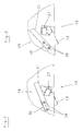
- Fig. 1
- eine schematische Seitenansicht einer Rundballenpresse mit einer erfindungsgemäßen Antriebs- und Schaltungsanordnung zum selektiven Antrieb einer Abzugs- und Zuführvorrichtung;
- Fig.2
- eine schematische, teilweise abgebrochene, perspektivische Darstellung der Antriebs- und Schaltungsanordnung in einer Phase, in der die Abzugs- und Zuführvorrichtung nicht angetrieben wird;
- Fig.3
- eine schematische, teilweise abgebrochene, perspektivische Darstellung der Antriebs- und Schaltungsanordnung in einer Phase während des Umhüllungsvorganges;
- Fig.4
- eine vergrößerte perspektivische Ansicht der in Fig.2 markierten und als Einzelheit X bezeichneten Messerbaugruppe der Schneideinrichtung in Schneidendstellung mit einer Blickrichtung gemäß Pfeil A;
- Fig.5
- eine vergrößerte perspektivische Ansicht der in Fig.3 markierten und als Einzelheit Y bezeichneten Messerbaugruppe der Schneideinrichtung in Schneidausgangsstellung mit einer Blickrichtung gemäß Pfeil B;
- Fig.6
- eine schematische, teilweise abgebrochene, perspektivische Darstellung der Innenseite einer in Fahrtrichtung rechten Seitenwand der Rundballenpresse mit einer daran angebrachten Abzugs- und Zuführvorrichtung in einer Blickrichtung aus einer Position seitlich links und hinter der Rundballenpresse;
- Fig. 1
- is a schematic side view of a round baler with a drive and circuit arrangement according to the invention for the selective drive of a trigger and feed device;
- Fig. 2
- is a schematic, partially broken, perspective view of the drive and circuit arrangement in a phase in which the trigger and feed device is not driven;
- Fig. 3
- a schematic, partially broken, perspective view of the drive and circuit arrangement in one phase during the wrapping process;
- Fig. 4
- an enlarged perspective view of the knife assembly marked in FIG. 2 and designated as detail X of the cutting device in the cutting end position with a viewing direction according to arrow A;
- Fig. 5
- an enlarged perspective view of the knife assembly marked in FIG. 3 and designated as detail Y of the cutting device in the cutting starting position with a viewing direction according to arrow B;
- Fig. 6
- is a schematic, partially broken, perspective view of the inside of a right side wall in the direction of travel of the round baler with an attached pulling and feeding device in a viewing direction from a position to the left and behind the round baler;
Die in Fig.1 veranschaulichte Rundballenpresse 1 zum
Aufnehmen und Pressen von Heu, Stroh, angewelktem Gras
oder dgl. landwirtschaftlichen Erntegut zu zylindrischen
Ballen stützt sich über Laufräder 2,3 und 4,5 in
Form einer Tandemachse gegenüber dem Erdboden ab und
kann mittels einer Deichsel 6 an einen nicht dargestellten,
landwirtschaftlichen Ackerschlepper oder dgl. Zugmaschine
angehängt werden. Der Antrieb der Rundballenpresse
1 erfolgt über eine ebenfalls nicht dargestellte
Gelenkwellenverbindung, die antriebsmäßig mit dem Ackerschlepper
zu koppeln ist. Die Rundballenpresse 1 beinhaltet
im wesentlichen eine Aufsammelvorrichtung 7 sowie
eine dieser nachgeschalteten Förder-und Schneidvorrichtung
8 und einen eine Gutzuführöffnung 9 beinhaltenden
und von Wickelelementen umfangseitig begrenzten Wikkelraum
10 zur Formung von zylindrischen Ballen mit unterschiedlichen
Ballendurchmessern. Gleichermaßen ist
es aber auch möglich, der Erfindung eine Rundballenpresse
mit anderer Bauart zugrunde zu legen, insbesondere
eine Rundballenpresse mit unveränderlicher Größe des
Wickelraumes.The
Wie weiterhin aus Fig.1 hervorgeht, weist die Rundballenpresse
1 eine Umhüllungsvorrichtung 11 auf, die eine
Abzugs- und Zuführvorrichtung 12 zum Abziehen einer
Hüllbahn 13 bestimmter Länge von einer Materialrolle 14
und zum Zuführen der Hüllbahn 13 in den Wickelraum 10
sowie eine der Abzugs- und Zuführvorrichtung 12 nachgeordneten
Schneideinrichtung 15 umfaßt. Zum Antrieb und
zur Betätigung der Abzugs- und Zuführvorrichtung 12 ist
eine Antriebs- und Schaltungsanordnung 16 vorgesehen,
welche im wesentlichen aus einem Riementrieb 17 mit einer
antreibenden Riemenscheibe 18, einer angetriebenen
Riemenscheibe 19 und dem Riemen 20, sowie aus einer an
einem Spannarm 21 angebrachten und von einem Stellglied
23 zu betätigenden Spannrolle 22 besteht.As can further be seen from FIG. 1, the round baler has
1 a
In den Figuren 2 und 3 ist die Antriebs- und Schaltungsanordnung
16 in den jeweiligen Schaltstellungen näher
veranschaulicht. Wie aus diesen Figuren hervorgeht, umfaßt
die Abzugs- und Zuführvorrichtung 12 eine sich
quer zur Fahrtrichtung F der Rundballenpresse 1 erstrekkende
und um die Mittelachse 24 drehbar gelagerte Abzugswalze
25 und eine oberhalb von dieser angeordneten
Andruckrolle 26. Da die Verbindung zwischen der Riemenscheibe
19 des Riementriebes 17 und der Abzugswalze 25
eine Freilaufkupplung enthält, ist es möglich, die Abzugswalze
25 wahlweise von der Riemenscheibe 19 des Riementriebes
17 oder mit einer höheren Drehzahl von der
durch den sich drehenden Ballen abgezogenen Hüllbahn 13
in eine Drehbewegung zu versetzen. Die der Abzugs- und
Zuführvorrichtung 12 nachgeschaltete Schneideinrichtung
15 setzt sich aus einer Messerbaugruppe 27 sowie aus
einem mittels Befestigungsschrauben 28 mit der Messerbaugruppe
27 verschraubten Führungs- und Steuerungselement
29 zusammen, welches seinerseits als Tastarm 30
ausgeführt ist. Der Tastarm besteht dabei aus einer bezüglich
seiner Querausrichtung biegsamen Federlamelle
31, an dessen freiem Ende sich eine Laufrolle 32 befindet. In Figures 2 and 3 is the drive and
Zur Überführung der Messerbaugruppe 27 der Schneideinrichtung
15 aus einer die Ruhelage bildenden Schneidendstellung
(Fig 4) in eine Schneidausgangsstellung
(Fig.5) weist die Antriebs- und Schaltungsanordnung 16
eine Steuerkurve 33 auf, die um die Mittelachse 24 der
Abzugswalze 25 drehbar gelagert ist. Die Steuerkurve 33
umfaßt dazu einen kurvenförmigen Steg 34 mit einem auf
einem Teil der Außenkontur des Steges 34 angebrachten
Abdeckelement 35. Zur Bildung einer Abwurfkante 36 ist
das Abdeckelement 35 einenends schräg abgeschnitten,
wobei die schräge Schnittkante so gewählt ist, daß die
Schnittkante des Abdeckelementes 35 und der kurvenförmige
Steg 34 einen spitzen Winkel einschließen. An der
der Laufrolle 32 des Tastarmes 30 zugewandten Seite des
Abdeckelementes 35 weist dieses eine Lauf- und Führungsfläche
37 auf, welche als Bewegungsbahn für die Laufrolle
32 dient.To transfer the
In dem dargestellten Ausführungsbeispiel (Fig.2 und 3)
ist das Stellglied 23 als Linearantriebsmotor 38 ausgebildet,
der einenends mit einem Federspeicher 39 zur
Konstanthaltung der Riemenspannung des Riementriebes 17
versehen ist. Durch den Federspeicher 39 an dem der
Spannrolle 22 zugewandten Ende des Linearantriebsmotors
38 wird es ermöglicht, daß sich die zur Erreichung einer
ausreichenden Riemenspannung des Riemens 20 erforderliche
Länge des Linearantriebsmotors 38 selbsttätig
einstellt. In the illustrated embodiment (Fig. 2 and 3)
Zur Feststellung des jeweiligen Umhüllungsgrades des
Ballens während des Umhüllungsvorganges sind Erkennungsmittel
40 vorgesehen, die der Abzugswalze 25 der Abzugs-
und Zuführvorrichtung 12 zugeordnet sind (Fig.6).
Diese können als Signalscheibe 41 mit am Umfang gleichmäßig
verteilten Aussparungen ausgeführt sein, wobei
die Anzahl der Aussparungen/Zählimpulse von einem Zählelement
42 erfaßt werden.To determine the respective degree of wrapping of the
Bales during the wrapping process are detection means
40 provided that the take-off
Die Betriebsweise der erfindungsgemäßen Rundballenpresse
1 stellt sich wie folgt dar:The operation of the round baler according to the
Das von der Aufsammelvorrichtung 7 aufgenommene und
über die Förder- und Schneidvorrichtung 8 dem Wickelraum
10 zugeführte Erntegut wird dort zu zylindrischen
Ballen gepreßt und nachfolgend mit einem Abschnitt einer
Hüllbahn 13 umfangseitig umhüllt. Zur Einleitung
des Umhüllungsvorganges wird durch das vollständige Ausfahren
des als elektrischer Linearantriebsmotor 38 ausgebildeten
Stellgliedes 23, ausgelöst beispielsweise
durch einen Tastendruck des Bedieners an einer Bedienund
Steuerungseinheit der Rundballenpresse 1, aus der
ganz eingefahrenen in die ganz ausgefahrene Stellung
bewegt. Dadurch erfolgt eine Schwenkbewegung der Spannrolle
22 des Riementriebes 17 aus der Ausgangslage in
die den Riemen 20 spannende Lage und damit gekoppelt
eine Schwenkbewegung der Steuerkurve 33 aus der Ausgangslage
(Fig.2) in die Endlage (Fig.3) zur Überführung
der Messerbaugruppe 27 der Schneideinrichtung 15
aus der die Ruhelage bildenden Schneidendstellung
(Fig.4) in die Schneidausgangsstellung (Fig.5). Dadurch
wird die Abzugswalze 25 der Abzugs- und Zuführvorrichtung
12 in eine Drehbewegung versetzt und somit ein Abschnitt
der Hüllbahn 13 dem Wickelraum 10 der Rundballenpresse
1 zugeführt.The picked up by the collecting
Der Zuführvorgang der Hüllbahn 13 in den Wickelraum 10
dauert so lange an, bis die Hüllbahn 13 von dem sich
drehenden Ballen erfaßt wird, so daß von nun an die
Hüllbahn 13 von dem sich drehenden Ballen abgezogen
wird. Da das Abziehen der Hüllbahn 13 durch den sich
drehenden Ballen mit einer höheren Abzugsgeschwindigkeit
erfolgt, kann dieser Zeitpunkt als eigentlicher
Anfangszeitpunkt des Umhüllungsvorganges gewertet werden.
Zu diesem Zeitpunkt beginnt auch eine Messung der
Länge der abgezogenen Hüllbahn 13 zur Feststellung des
Umhüllungsgrades des Ballens durch eine Zählung der Aussparungen/Zählimpulse
der Signalscheibe 41 mittels des
Zählelementes 42 (Fig.6). Die Anzahl der Zählimpulse
können nun einer Bedien- und Steuerungseinheit zugeführt
und dort beispielsweise als Auslösesignal zur Beendigung
des Umhüllungsvorganges verwendet werden.The feeding process of the wrapping
Nachdem Erreichen eines vorgewählten Umhüllungsgrades
wird nun durch das Einfahren des elektrischen Linearantriebsmotors
38 aus der ganz ausgefahrenen in die ganz
eingefahrene Stellung der Umhüllungsvorgang beendet.
Dies kann einerseits durch eine sogenannte Handsteuerung
eingeleitet werden oder andererseits als Folge einer
Auswertung der Zählimpulse des Zählelementes 42 in
Verbindung mit dem vorhandenen Ballendurchmesser automatisch
ausgelöst werden. Dabei wird durch eine Schwenkbewegung
der Spannrolle 22 der Riementrieb 17 entspannt
und damit gekoppelt die Steuerkurve 33 aus der Endlage
(Fig.3) in die Ausgangslage (Fig.2) zurückgeschwenkt.
Dabei erfolgt durch den Abwurf der Laufrolle 32 des
Tastarmes 30 durch die Abwurfkante 36 von Steuerkurve
33 eine schlagartige Überführung der Messerbaugruppe 27
aus der Schneidausgangsstellung (Fig.5) in die Schneidendstellung
(Fig.4), so daß dadurch ein sauberes Durchtrennen
der Hüllbahn 13 erreicht wird.After reaching a pre-selected degree of wrapping
is now by retracting the electric
Obwohl in den Zeichnungen und in der Beschreibung eine
bevorzugte Ausführungsform dargelegt wurde, sind durchaus
weitere Modifikationen und Ausführungsvarianten vorstellbar.
So ist es beispielsweise denkbar, dem Tastarm
30 einen Abwurfnocken zu zuordnen, über den dann durch
den Abwurf der Laufrolle 32 des Tastarmes 30 von der
Steuerkurve 33 ein Durchtrennen der Hüllbahn 13 bewirkt
wird.Although in the drawings and in the description
preferred embodiment has been set out, are quite
further modifications and design variants conceivable.
So it is conceivable, for example, the
Claims (16)
- A round baling press having winding elements bounding the periphery of the winding space and leaving an aperture for the feeding of materials and with a pull-off and feed apparatus (12) with, associated with these latter, a cutting means (15) for pulling off a covering web (13) of specific length from a material roll (14) and for feeding the covering web (13) into the winding space of the round baling press for the peripheral wrapping of a finished bale with a driving and switching arrangement for the selective driving of the pull-off and feed means (12), the driving and switching arrangement comprising a belt transmission which can be switched on and off by means of a tensioning pulley (22) and which is so constructed that in synchronism with the belt transmission (17) being switched on, there is a transfer of the cutting means (15) out of the cutting finishing position which constitutes the inoperative position into a cutting starting position and, by the belt transmission (17) being switched off, a transfer of the cutting means (15) out of the cutting starting position into the cutting finishing position is reached and whereby, by means of a positioning member (23), the tensioning pulley (22) of the belt transmission (17) is moved out of a starting position into a position in which the belt (20) of the belt transmission (17) is tensioned, a cutting blade assembly (27) of the cutting means (15) being capable of being transferred by a guiding and controlling element (29) which is guided on a cam (33) to move out of the cutting finishing position which constitutes the inoperative position into a cutting starting position in which it is not engaged with a passing portion of the covering web (13) and stopped and in that after the bale has been wrapped to a degree which is chosen and established by acknowledging means (40), the tensioning pulley (22) is moved back out of the position in which it tensions the belt (20) of the belt transmission (17) into the starting position and consequently couples the cutting blade assembly (27) with the cutting means (15) abruptly by the guiding and controlling elements (29) being thrown off the cam (33) by virtue of, disposed obliquely to the running and guiding surface (37) of the cam (33), a throw-off edge (36) out of the cutting starting position into the cutting finishing position.
- A round baling press according to claim 1, characterised in that the guiding and controlling element (29) is constructed as a sensing arm (30) connected to the cutting blade assembly (27) of the cutting means (15) and on the free end of which there may be a freely running pulley (32) or a sliding member.
- A round baling press according to claim 1 and 2, characterised in that the sensing arm (30) is constructed as a leaf spring (31) adapted to be flexible in relation to its transverse orientation.
- A round baling press according to one of claims 1 to 3, characterised in that the tensioning pulley (22) of the belt transmission (17) and which is mounted on the tensioning arm (21) and the cam (33) for transferring the cutter blade assembly (27) of the cutting means (15) out of the cutting finishing position into the cutting starting position and back are mounted to pivot about the common pivot axis.
- A round baling press according to claim 4, characterised in that the tensioning pulley (22) of the belt transmission (17) which is mounted on the tensioning arm (21) and the cam (33) for transferring the cutting blade assembly (27) of the cutting means (15) out of the cutting finishing position into the cutting starting position and back are mounted to be pivotable about a central axis (24) of a pull-off roller (25) of the pull-off and feeding means (12).
- A round baling press according to one of claims 1 to 5, characterised in that the cam (33) comprises a curvilinear web (34) with a covering element (35) mounted on a part of the outer contour of the web (34).
- A round baling press according to one of claims 1 to 6, characterised in that the covering element (35) of the cam (33) is cut obliquely at one end.
- A round baling press according to one of claims 1 to 7, characterised in that the tensioning arm (21) for accommodating the tensioning pulley (22) of the belt transmission (17) is rigidly connected to the cam (33).
- A round baling press according to one of claims 1 to 8, characterised in that the connection between a belt pulley (19) of the belt transmission (17) and the pull-off roller (25) of the pull-off and feeding means (12) comprises a freewheel coupling.
- A round baling press according to one of claims 1 to 9, characterised in that in the case of the positioning member (23) for transferring the tensioning pulley (22) from the starting position into the position in which the belt (20) of the belt transmission (17) is tensioned and back into the starting position is only a fully retracted or fully extended switched position.
- A round baling press according to one of claims 1 to 10, characterised in that the positioning member (23) has a spring storage means (39) at one end.
- A round baling press according to one of claims 1 to 11, characterised in that the positioning member (23) can be electrically operated.
- A round baling press according to one of claims 1 to 12, characterised in that the positioning member (23) is an electrical linear drive motor (33).
- A round baling press according to one of claims 1 to 13, characterised in that recognition means (40) for establishing the particular degree of wrapping of the bale are associated with the pull-off roller (25) of the pulling-off and feeding means (12).
- A round baling press according to one of claims 1 to 14, characterised in that the recognition means (14) provided is a signal disc (41) with cut-outs distributed evenly over its periphery and with which a counting element (42) is associated.
- A round baling press according to one of claims 1 to 15, characterised in that the counting pulses registered by the counting element (42) are adapted to be fed to an operating and control unit.
Applications Claiming Priority (2)
| Application Number | Priority Date | Filing Date | Title |
|---|---|---|---|
| DE19626525 | 1996-07-02 | ||
| DE19626525A DE19626525C1 (en) | 1996-07-02 | 1996-07-02 | Round baler |
Publications (2)
| Publication Number | Publication Date |
|---|---|
| EP0815719A1 EP0815719A1 (en) | 1998-01-07 |
| EP0815719B1 true EP0815719B1 (en) | 2001-07-11 |
Family
ID=7798657
Family Applications (1)
| Application Number | Title | Priority Date | Filing Date |
|---|---|---|---|
| EP97109981A Expired - Lifetime EP0815719B1 (en) | 1996-07-02 | 1997-06-19 | Roundbaler |
Country Status (2)
| Country | Link |
|---|---|
| EP (1) | EP0815719B1 (en) |
| DE (2) | DE19626525C1 (en) |
Families Citing this family (2)
| Publication number | Priority date | Publication date | Assignee | Title |
|---|---|---|---|---|
| GB0130465D0 (en) * | 2001-12-20 | 2002-02-06 | Kverneland Asa | Baler and enveloping apparatus |
| US10736272B2 (en) | 2018-03-09 | 2020-08-11 | Deere & Company | Material wrap system with automatic drive tension compensation |
Family Cites Families (7)
| Publication number | Priority date | Publication date | Assignee | Title |
|---|---|---|---|---|
| DE8324503U1 (en) * | 1983-08-26 | 1986-03-06 | Claas Ohg, 4834 Harsewinkel | Large baler for agricultural crops |
| DE3418681A1 (en) * | 1984-05-19 | 1985-11-21 | Gebrüder Welger GmbH & Co KG, 3340 Wolfenbüttel | Rolled-bale press for agricultural stalk crops, having a wrapping device |
| DE3601361C2 (en) * | 1986-01-18 | 1994-04-07 | Claas Ohg | Roller baler |
| EP0293025B1 (en) * | 1987-05-01 | 1993-02-10 | FORD NEW HOLLAND, INC. (a Delaware corp.) | Knife assembly for net dispensing apparatus |
| US4938004A (en) * | 1989-03-13 | 1990-07-03 | Ford New Holland, Inc. | Net wrapping method |
| US5433059A (en) * | 1993-04-27 | 1995-07-18 | Agco Corporation | Round bale wrapping |
| DE29609555U1 (en) * | 1996-05-29 | 1996-08-22 | Greenland Gmbh & Co Kg | Round baler |
-
1996
- 1996-07-02 DE DE19626525A patent/DE19626525C1/en not_active Expired - Fee Related
-
1997
- 1997-06-19 DE DE59703997T patent/DE59703997D1/en not_active Expired - Lifetime
- 1997-06-19 EP EP97109981A patent/EP0815719B1/en not_active Expired - Lifetime
Also Published As
| Publication number | Publication date |
|---|---|
| DE19626525C1 (en) | 1997-12-11 |
| DE59703997D1 (en) | 2001-08-16 |
| EP0815719A1 (en) | 1998-01-07 |
Similar Documents
| Publication | Publication Date | Title |
|---|---|---|
| DE3322024C1 (en) | Wrapping device for round bales in balers | |
| EP1170984B1 (en) | Method of wrapping a round bale compacted by a round baler, film-wrapping device and round baler that is provided with such a film-wrapping device | |
| EP1461995B2 (en) | Device for wrapping a bale with an envelope, baling press and sensor | |
| EP2861055B1 (en) | Twine knotter | |
| DE2705101A1 (en) | Weatherproof packaged straw bales - are wrapped in helically wound overlapping web of UV stabilised polyethylene | |
| DE3418681A1 (en) | Rolled-bale press for agricultural stalk crops, having a wrapping device | |
| EP0366936B1 (en) | Method and apparatus for making highly compressed cylindrical articles from cut crop | |
| DE4442479C2 (en) | Monitoring and control system for balers | |
| DE2826904C2 (en) | ||
| EP1064839B1 (en) | Device to fix a loose end of twine on a round bale | |
| DE3150614A1 (en) | Automatic tying-round device on agricultural rolled-bale presses | |
| DE4132664C2 (en) | Bale binding method and apparatus therefor | |
| WO1986001974A1 (en) | Process and device for producing large bales from cut plant materials | |
| DE3617155A1 (en) | Round-bale press | |
| EP0815719B1 (en) | Roundbaler | |
| DE2530320B2 (en) | Tying device for baling presses | |
| DE2640563C3 (en) | Tying device on round balers | |
| EP3300585B1 (en) | Round-bale press for holding and pressing agricultural produce | |
| DE19705582B4 (en) | Round baler | |
| EP1878333B1 (en) | Binding device on agricultural round balers | |
| DE10309658A1 (en) | Agricultural baling device for wrapping a bale has a sensor for monitoring the path of the wrapping web to ensure it is following a predetermined path and quickly detect a breakage or miss-feed | |
| DE19837265A1 (en) | Round baler | |
| EP3530106A1 (en) | Node device | |
| DE19720542A1 (en) | Securing device for yarn ends on pressed bale | |
| EP3090622B1 (en) | Balling press for agricultural harvested materials |
Legal Events
| Date | Code | Title | Description |
|---|---|---|---|
| PUAI | Public reference made under article 153(3) epc to a published international application that has entered the european phase |
Free format text: ORIGINAL CODE: 0009012 |
|
| AK | Designated contracting states |
Kind code of ref document: A1 Designated state(s): DE FR NL |
|
| 17P | Request for examination filed |
Effective date: 19980512 |
|
| AKX | Designation fees paid |
Free format text: DE FR NL |
|
| RBV | Designated contracting states (corrected) |
Designated state(s): DE FR NL |
|
| RAP1 | Party data changed (applicant data changed or rights of an application transferred) |
Owner name: MASCHINENFABRIK BERNARD KRONE GMBH |
|
| GRAG | Despatch of communication of intention to grant |
Free format text: ORIGINAL CODE: EPIDOS AGRA |
|
| GRAG | Despatch of communication of intention to grant |
Free format text: ORIGINAL CODE: EPIDOS AGRA |
|
| GRAH | Despatch of communication of intention to grant a patent |
Free format text: ORIGINAL CODE: EPIDOS IGRA |
|
| 17Q | First examination report despatched |
Effective date: 20001023 |
|
| GRAH | Despatch of communication of intention to grant a patent |
Free format text: ORIGINAL CODE: EPIDOS IGRA |
|
| GRAA | (expected) grant |
Free format text: ORIGINAL CODE: 0009210 |
|
| AK | Designated contracting states |
Kind code of ref document: B1 Designated state(s): DE FR NL |
|
| REF | Corresponds to: |
Ref document number: 59703997 Country of ref document: DE Date of ref document: 20010816 |
|
| ET | Fr: translation filed | ||
| ET1 | Fr: translation filed ** revision of the translation of the patent or the claims | ||
| PLBE | No opposition filed within time limit |
Free format text: ORIGINAL CODE: 0009261 |
|
| STAA | Information on the status of an ep patent application or granted ep patent |
Free format text: STATUS: NO OPPOSITION FILED WITHIN TIME LIMIT |
|
| 26N | No opposition filed | ||
| REG | Reference to a national code |
Ref country code: FR Ref legal event code: PLFP Year of fee payment: 20 |
|
| PGFP | Annual fee paid to national office [announced via postgrant information from national office to epo] |
Ref country code: DE Payment date: 20160629 Year of fee payment: 20 |
|
| PGFP | Annual fee paid to national office [announced via postgrant information from national office to epo] |
Ref country code: NL Payment date: 20160626 Year of fee payment: 20 Ref country code: FR Payment date: 20160624 Year of fee payment: 20 |
|
| REG | Reference to a national code |
Ref country code: DE Ref legal event code: R071 Ref document number: 59703997 Country of ref document: DE |
|
| REG | Reference to a national code |
Ref country code: NL Ref legal event code: MK Effective date: 20170618 |