EP0128965A1 - Verfahren zum Betreiben eines metallurgischen Schmelzofens und metallurgischer Schmelzofen - Google Patents
Verfahren zum Betreiben eines metallurgischen Schmelzofens und metallurgischer Schmelzofen Download PDFInfo
- Publication number
- EP0128965A1 EP0128965A1 EP83105858A EP83105858A EP0128965A1 EP 0128965 A1 EP0128965 A1 EP 0128965A1 EP 83105858 A EP83105858 A EP 83105858A EP 83105858 A EP83105858 A EP 83105858A EP 0128965 A1 EP0128965 A1 EP 0128965A1
- Authority
- EP
- European Patent Office
- Prior art keywords
- furnace
- melting furnace
- melting
- slag
- oriel
- Prior art date
- Legal status (The legal status is an assumption and is not a legal conclusion. Google has not performed a legal analysis and makes no representation as to the accuracy of the status listed.)
- Granted
Links
Images

Classifications
-
- C—CHEMISTRY; METALLURGY
- C21—METALLURGY OF IRON
- C21C—PROCESSING OF PIG-IRON, e.g. REFINING, MANUFACTURE OF WROUGHT-IRON OR STEEL; TREATMENT IN MOLTEN STATE OF FERROUS ALLOYS
- C21C5/00—Manufacture of carbon-steel, e.g. plain mild steel, medium carbon steel or cast steel or stainless steel
- C21C5/52—Manufacture of steel in electric furnaces
- C21C5/5211—Manufacture of steel in electric furnaces in an alternating current [AC] electric arc furnace
-
- F—MECHANICAL ENGINEERING; LIGHTING; HEATING; WEAPONS; BLASTING
- F27—FURNACES; KILNS; OVENS; RETORTS
- F27B—FURNACES, KILNS, OVENS, OR RETORTS IN GENERAL; OPEN SINTERING OR LIKE APPARATUS
- F27B3/00—Hearth-type furnaces, e.g. of reverberatory type; Tank furnaces
- F27B3/06—Hearth-type furnaces, e.g. of reverberatory type; Tank furnaces with movable working chambers or hearths, e.g. tiltable, oscillating or describing a composed movement
- F27B3/065—Hearth-type furnaces, e.g. of reverberatory type; Tank furnaces with movable working chambers or hearths, e.g. tiltable, oscillating or describing a composed movement tiltable
-
- F—MECHANICAL ENGINEERING; LIGHTING; HEATING; WEAPONS; BLASTING
- F27—FURNACES; KILNS; OVENS; RETORTS
- F27B—FURNACES, KILNS, OVENS, OR RETORTS IN GENERAL; OPEN SINTERING OR LIKE APPARATUS
- F27B3/00—Hearth-type furnaces, e.g. of reverberatory type; Tank furnaces
- F27B3/10—Details, accessories, or equipment peculiar to hearth-type furnaces
- F27B3/19—Arrangements of devices for discharging
-
- F—MECHANICAL ENGINEERING; LIGHTING; HEATING; WEAPONS; BLASTING
- F27—FURNACES; KILNS; OVENS; RETORTS
- F27D—DETAILS OR ACCESSORIES OF FURNACES, KILNS, OVENS, OR RETORTS, IN SO FAR AS THEY ARE OF KINDS OCCURRING IN MORE THAN ONE KIND OF FURNACE
- F27D3/00—Charging; Discharging; Manipulation of charge
- F27D3/14—Charging or discharging liquid or molten material
-
- H—ELECTRICITY
- H05—ELECTRIC TECHNIQUES NOT OTHERWISE PROVIDED FOR
- H05B—ELECTRIC HEATING; ELECTRIC LIGHT SOURCES NOT OTHERWISE PROVIDED FOR; CIRCUIT ARRANGEMENTS FOR ELECTRIC LIGHT SOURCES, IN GENERAL
- H05B7/00—Heating by electric discharge
- H05B7/02—Details
-
- Y—GENERAL TAGGING OF NEW TECHNOLOGICAL DEVELOPMENTS; GENERAL TAGGING OF CROSS-SECTIONAL TECHNOLOGIES SPANNING OVER SEVERAL SECTIONS OF THE IPC; TECHNICAL SUBJECTS COVERED BY FORMER USPC CROSS-REFERENCE ART COLLECTIONS [XRACs] AND DIGESTS
- Y02—TECHNOLOGIES OR APPLICATIONS FOR MITIGATION OR ADAPTATION AGAINST CLIMATE CHANGE
- Y02P—CLIMATE CHANGE MITIGATION TECHNOLOGIES IN THE PRODUCTION OR PROCESSING OF GOODS
- Y02P10/00—Technologies related to metal processing
- Y02P10/20—Recycling
Definitions
- the invention relates to a method for operating a metallurgical melting furnace, in particular an electric, plasma or a furnace heated with primary energy, in which, after finished melting, the molten metal is largely tapped without slag by opening the molten metal off-center on the underside of the melting furnace Closure member is discharged vertically, the tapping process being controlled by tilting the melting furnace, and an alternating process in which the molten metal on the underside in the middle of the melting furnace is discharged vertically after opening the closure member, and a metallurgical melting furnace for carrying out the processes .
- the largely slag-free tapping forms the prerequisite for subsequent ladle metallurgical treatment with subsequent low-inclusion cast materials or in the melting shop for working with a liquid sump, e.g. in the case of iron sponge or scrap use.
- the interruption of the tapping process means that the entire tapping process has ended, but not yet an instruction as to how the slag can be prevented from acting during the tapping process.
- the object of the invention is therefore to counteract influences of the tapping flow on the slag floating on the molten metal (steel melt) during the tapping process, so that a largely slag-free tapping is made possible during the entire tapping process.
- the problem is solved in the circumstances on which the first alternative is based, in that, with a surface ratio of water-cooled wall surface / fire-resistant wall surface of 6: 1 to 9: 1, the melting furnace during the parting off only from 0 'to a maximum of + 15' or from 0 ° is tilted to a maximum of -6 °, that in the area of the closure member there is an uncritical melt bath depth when tilting forward of the melting furnace is maintained and that towards the end of the tapping, the slag floating on the remaining molten metal is displaced from the area of the closure member by tilting the melting furnace back.
- the first-mentioned measure saves refractory material in operation and therefore permits use in the smallest tilt angle range, which in turn is necessary for parting off, without touching the water-cooled pipe wall elements with the slag, which would be harmful.
- the tilt angle range mentioned it is then possible to continuously maintain an uncritical molten bath depth, as a result of which potential eddy formation from the tap opening is largely avoided, which in turn avoids suction on the slag layer, so that slag is prevented from being entrained into the molten metal to be cut off.
- the negative tilt angle range also only extends to -6 'in order to retain the slag still floating on the molten metal at the entry into the tap opening.
- the melt pool depth is also uncritical if no slag is drawn into the pouring opening at a low melt pool depth or if only the refractory material and not the water-cooled pipe wall elements are touched at a large melt pool depth. It would make little sense to achieve an increase in the quality of the end product (steel) on the one hand by slag-free tapping, but on the other hand to have to accept a high increase in operating costs (refractory costs, investment costs, lay-out costs and the like). The invention therefore allows the quality of the end product steel to be improved while at the same time reducing operating costs.
- the problem is solved in the circumstances on which the second alternative is based, in that the melting furnace remains in a vertical position during the parting with a surface ratio of water-cooled wall surface / refractory wall surface of 7: 1 to 10: 1, that the slag through Addition of stiffening agent is made viscous, so that the greatest depth of melt bath is continuously maintained in the area of the YerschluBorgans and that towards the end of tapping the remaining slag is deposited on the bottom of the vessel after a deslagging process.
- the slag layer becomes coherent and is less subject to the influences of the potential vortex.
- the potential vortex acts only slightly on the stiffened slag layer, which is reduced by slagging, so that the total amount of metal melt present can be tapped off.
- the bottom tapping allows an approximately laminar flow of the pouring jet. This makes it possible for the vessel located under the melting furnace to be adjusted to a maximum of 1 m of the vertical distance, measured from the error organ to the edge of the vessel.
- the metallurgical melting furnace for carrying out the method is equipped with an oriel part, in the bottom of which at least one tap opening is provided.
- the transition of the oriel part to the furnace interior exerts an influence on the formation of the potential vortex or on its effects.
- the melting furnace is therefore further developed in such a way that the oriel part with its inner boundary wall is approximately trapezoidal in plan, that the trapezoidal limbs walls in the region of the side facing the melt toward the circular or oval-shaped furnace interior, respectively run tangentially and that the tap hole is arranged on the trapezoidal axis.
- the potential vortex can be supported on at least three walls without finding a way into the slag layer. The slag layer therefore settles down to the bottom of the vessel.
- the oriel part with its inner boundary wall is rectangular in plan, that the side walls in the area facing the melting chamber run as parallel secants to the circular or oval furnace interior and that the tap opening is arranged centrally between the secants.
- the spacing of the secants means a measure for a calm lowering of the metal melt together with the slag floating on the metal melt.
- tap openings are provided at any point in the oriel part in such melting furnaces.
- the metallurgical melting furnace for the process stages of the first process has on the furnace trough 1 in the oriel part 2 on the underside the closure member 3, which e.g. can consist of a closable cap.
- the tap opening 4 is filled with a filling compound during the melting process and protects the closure member 3 from the influence of the molten metal, which, if made of steel, has a temperature of over 1,500 ° C.
- the molten steel 5 with the residual slag layer 6 extends just below the water-cooled wall surface 7 and only touches the refractory wall surface 8 made of refractory masonry stones.
- the slag tap opening 9 is provided for removing the main slag.
- the melting furnace can be tilted by means of a tilting device, which is not shown, and is provided with a tilting drive which allows fine-level tilting or, alternatively, continuous tilting.
- the surface ratio of the water-cooled wall surface 7 and the refractory wall surface 8, as drawn, is approximately 7: 1.
- the melting furnace reaches a tilt position of approximately 5 °, as a result of which a sufficiently large bath depth above the tap opening 4 is present, which avoids potential eddies.
- the pouring jet 10 leaves the opened closure member 3 almost in a laminar flow.
- the melt bath depth above the tap opening 4 is still sufficient to avoid potential eddies.
- the process steps of the second process alternative are described with reference to FIGS. 5 to 8.
- the surface ratio of the water-cooled wall surface 7 to the refractory wall surface 8 is approximately 9: 1 here, which is made possible because the melting furnace is perpendicular in the first phase (FIG. 5).
- the residual slag layer 6 is stiffened with lime in the first phase, so that the slag acts like a solid ceiling.
- the closure member 3 is opened in the second phase, the molten metal flows out of the furnace trough 1 in the center as a pouring jet 10 with approximately laminar flow into a vessel (not shown in more detail) about 1 m below.
- the furnace trough 1 is trough-shaped, and a bay part is completely missing here.
- the metallurgical melting furnace according to FIG. 8 has the oriel part 2, the inner boundary wall 12 of which is trapezoidal.
- the trapezoidal leg walls 13a and 13b run in the direction of the melting space 14 tangentially to the circular or oval furnace interior 15.
- the tap opening 4 is arranged on the trapezoidal axis 16.
- a tap hole 4a can also be provided in the central axis 17 of the furnace interior 15.
Landscapes
- Engineering & Computer Science (AREA)
- Mechanical Engineering (AREA)
- General Engineering & Computer Science (AREA)
- Chemical & Material Sciences (AREA)
- Materials Engineering (AREA)
- Organic Chemistry (AREA)
- Physics & Mathematics (AREA)
- Plasma & Fusion (AREA)
- Metallurgy (AREA)
- Manufacturing & Machinery (AREA)
- Vertical, Hearth, Or Arc Furnaces (AREA)
- Feeding, Discharge, Calcimining, Fusing, And Gas-Generation Devices (AREA)
- Furnace Charging Or Discharging (AREA)
Abstract
Description
- Die Erfindung betrifft ein Verfahren zum Betreiben eines metallurgischen Schmelzofens, insbesondere eines Elektro-, Plasma- bzw. eines mit Primärenergie beheizten Schmelzofens, bei dem nach Fertigschmel zen die Metallschmelze weitestgehend schlackenfrei abgestochen wird, indem die Metallschmelze außermittig an der Unterseite des Schmelzofens nach öffnen eines Verschlußorgans senkrecht abgelassen wird, wobei der Abstichvorgang über das Kippen des Schmelzofens gesteuert wird, und ein dazu alternierendes Verfahren, bei dem die Metallschmelze an der Unterseite in der Mitte des Schmelzofens nach öffnen des Verschlußorgans lotrecht abgelassen wird, sowie einen metallurgischen Schmelzofen zur Durchführung der Verfahren.
- Derartige Betriebsverfahren bzw. Schmelzofen arbeiten mit einem Bodenabstich, aus dem der Gießstrahl in Annäherung an eine laminare Strömung austritt. Es sind jedoch Zusatzmaßnahmen erforderlich, um Schlacke und flüssige Metallschmtelze, insbesondere Stahlschmelze, vor dem Abstich an einem Durchmischen zu hindern. Das Stoppen mitauslaufender Schlacke am Ende des Abstechens erfolgt bei kippbaren Schmelzöfen in der Weise, indem bei exzentrischem Bodenabstich über die Kippbewegung des Ofens ein gezieltes Unterbrechen des Abstichvorganges eingeleitet wird.
- Der weitestgehend schlackenfreie Abstich bildet die Voraussetzung für nachfolgende pfannenmetallurgische Behandlung mit nachfolgenden einschlußarmen Gußwerkstoffen bzw. im Schmelzbetrieb für das Arbeiten mit flüssigem Sumpf, z.B. im Fall von Eisenschwamm- oder Schrotteinsatz.
- Die Unterbrechung des Abstichvorganges bedeutet eine Beendigung des gesamten Abstichverfahrens, jedoch noch keine Anweisung, wie während des Abstichvorganges eine Einwirkung der sich ausbildenden Strömung auf die Schlacke verhindert werden kann.
- Es ist bekannt (DE-OS 18 04 007), die Entleerung des Schnelzofens erst dann beginnen zu lassen, wenn das Verschlußorgan in der äußersten Kippstellung des Schmelzofens geöffnet wird. Diese Verfahrenweise nimmt auf das Zusammenspiel der Metallschmelzenströmungen, die insbesondere bei Stahl von besonderer Bedeutung sind, und Schlacke keinerlei Rücksicht.
- Es ist ferner bekannt (DE-OS 29 44 269), den Schmelzofen mit einen erkerartigen Vorsprung zu versehen, dessen Innenraum mit dem Ofenraum über eine im seitlichen Bodenbereich des wannenförmigen Gefäßteils vorgesehene Durchflußöffnung verbunden ist. Hier wird jedoch die Metallschmelze innerhalb des Erkerteils mittels eines auf dem Metallbad schwimmenden Verschlußkörpers von der Schlacke getrennt, so daß ein schlackenfreies Abstechen vom Vorhandensein und von der Wirkung dieses schwimmenden Verschlußkörpers abhängig ist. Das Abbrechen des Abstichvorganges kann jedoch nur gegen Ende des Verfahrensabschnittes ein totales Mitauslaufen der Schlacke verhindern, um damit einen größeren Nachteil zu beseitigen. Es sind jedoch bisher keine Maßnahmen in Betracht gezogen worden, die vor der Beendigung des Abstichvorganges wirken.
- Der Erfindung liegt deshalb die Aufgabe zugrunde, Einflüssen der Abstichströmung auf die auf der Metallschmelze (Stahl schmel ze) schwimmende Schlacke während des Abstichvorganges entgegenzuwirken, so da3 ein weitestgehend schlackenfreies Abstechen während des gesamten Abstichvorganges ermöglicht wird.
- Die gestellte Aufgabe wird bei den der ersten Alternative zugrundegelegten Gegebenheiten dadurch gelöst, daß bei einem Oberflächenverhältnis von wassergekühlter Wandfläche/feuerfester Wandfläche von 6 : 1 bis 9 : 1 der Schmelzofen während des Abstechens lediglich von 0' bis maximal + 15' bzw. von 0° bis maximal -6° gekippt wird, daß im Bereich des Verschlußorgans fortwährend eine unkritische Schmelzbadtiefe beim Vorwärtskippen des Schmelzofens aufrechterhalten wird und daß gegen Ende des Abstechens die auf der restlichen Metallschmelze schwimmende Schlacke durch Zurückkippen des Schmelzofens aus dem Bereich des Verschlußorgans verlagert wird. Die zuerst genannte Maßnahme erspart im Betrieb Feuerfestmaterial und gestattet demnach die Anwendung bei einem kleinsten Kippwinkelbereich, der wiederum für das Abstechen erforderlich ist, ohne mit der Schlacke wassergekühlte Rohrwandelemente zu berühren, was schädlich wäre. Mit dem genannten Kippwinkelbereich Ist sodann möglich, eine unkritische Schmelzbadtiefe kontinuierlich einzuhalten, wodurch eine Potentialwirbelbildung ausgehend von der Abstichöffnung weitgehend vermieden wird, was wiederum einen Sog auf die Schlackenschicht vermeidet, so daß das Mitreißen von Schlacke in die abzustechende Metallschmelze verhindert wird. Der negative Kippwinkelbereich reicht ebenfalls nur bis -6', um die noch auf der Metallschmelze schwimmende Schlacke am Eintritt in die Abstichöffnung zurückzuhalten.
- Unkritisch ist die Schmelzbadtiefe außerdem dann, wenn bei niedriger Schmelzbadtiefe noch keine Schlacke in die Ausgießöffnung gesogen wird oder wenn bei großer Schmelzbadtiefe ausschließlich das Feuerfestmaterial berührt wird und nicht etwa die wassergekühlten Rohrwandelemente. Es wäre nämlich wenig sinnvoll, durch schlackenfreies Abstechen einerseits zwar eine Qualitätssteigerung des Endproduktes (Stahl) zu erzielen, andererseits jedoch einen hohen Anstieg der Betriebskosten (Feuerfestkosten, Investitionskosten, lay-out-Kosten und dgl.) in Kauf nehmen zu müssen. Die Erfindung gestattet daher eine Qualitätsverbesserung des Endproduktes Stahl bei gleichzeitiger Betriebskostensenkung.
- Die gestellte Aufgabe wird bei den der zweiten Alternativen zugrundegelegten Gegebenheiten dadurch gelöst, daß bei einem Oberflächenverhältnis von wassergekühlter Wandfläche/feuerfester Wandfläche von 7 : 1 bis 10 : 1 der Schmelzofen während des Abstechens in lotrechter Position verbleibt, daß die Schlacke durch Zugabe von Absteifmittel zähflüssig gemacht wird, daß im Bereich des YerschluBorgans fortwährend die jeweils größte Schmelzbadtiefe aufrechterhalten wird und daß gegen Ende des Abstechens die nach einen Abschlackvorgang vorhandene Restschlacke auf dem Gefäßboden abgelagert wird. Nach dieser Verfahrensweise kann noch mehr Feuerfestmaterial im Betrieb eingespart werden. Die Schlackenschicht wird zusammenhängend und unterliegt in geringerem Maß den Einflüssen des Potentialwirbel s. Im allgemeinen wirkt der Potentialwirbel hier nur gering auf die versteifte und durch Abschlacken verringerte Schlackenschicht ein, so daß die Gesamtmenge der vorhandenen Metallschmelze abgestochen werden kann.
- Beide Verfahrens-Alternativen bewirken verringerte Temperaturverluste, so daß bei einer jeweils um ca. 20°C gegenüber der qualitäts- bzw. nachbehandlungsabhängigen Abstichtemperatur verminderten Abstichtemperatur die Metallschmelze abgelassen wird.
- Der Bodenabstich gestattet eine näherungsweise laminare Strömung des Gießstrahls. Es wird dadurch möglich, daß das unter dem Schmel zofen befindliche Gefäß bis maximal 1m des lotrechten Abstandes, gemessen vom VersehluBorgan bis zum Gefäßrand, eingestellt wird.
- Der metallurgische Schmelzofen zur Durchführung des Verfahrens ist mit einem Erkerteil ausgestattet, in dessen Boden zumindest eine Abstichöffnung vorgesehen ist. Der Übergang des Erkerteils auf den Ofeninnenraum Ubt einen Einfluß auf die Ausbildung des Potentialwirbels bzw. auf dessen Wirkungen aus.
- Nach der weiteren Erfindung ist der Schmelzofen daher dahingehend weitergestaltet, daß der Erkerteil mit seiner inneren Begrenzungswand im Grundriß angenähert trapezförmig ausgebildet ist, daß die Trapezschenkel wände im Bereich der dem Schmel zr aum zugewandten Seite zu den kreisförmigen bzw. ovalförmigen 0feninnenraum jeweils tangential verlaufen und daß die Abstichöffnung auf der Trapezachse angeordnet ist. Solange die Schmelzbadtiefe unkritisch ist, kann sich der Potentialwirbel zumindest an drei Wänden abstützen, ohne einen Weg in die Schlackenschicht zu finden. Die Schlackenschicht senkt sich daher beruhigt auf den Gefäßboden ab.
- Eine andere Möglichkeit, den Potentialwirbel von der Schlacke fernzuhalten, besteht darin, daß der Erkerteil mit seiner inneren Begrenzungswand im Grundriß rechteckförmig ausgebildet ist, daß die Seitenwände im Bereich der dem Schmelzraum zugewandten Seite zu dem kreisförmigen bzw. ovalförmigen Ofeninneraum als parallele Sekanten verlaufen und daß die Abstichöffnung mittig zwischen den Sekanten angeordnet ist. Hier bedeutet der Abstand der Sekanten ein Maß für ein beruhigtes Absenken der Metallschmelze zusammen mit der auf der Metallschmelze schwimmenden Schlacke.
- Im allgemeinen sind bei derartigen Schmelzöfen Abstichöffnungen im Erkerteil an einer beliebigen Stelle vorgesehen. Gemäß einer Verbesserung der Erfindung sind entweder nur das Abstichloch im Erkerteil oder nur das Abstichloch in der Mittelachse des Ofeninnenraums vorgesehen, oder sind sowohl im Ofeninnenraum als auch im Erkerteil jeweils ein gesondertes Abstichloch vorgesehen.
- Mehrere Ausführungsbeispiele sind in der Zeichnung dargestellt, anhand deren auch die Verfahren erläutert werden. Es zeigen
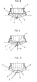
- Fig. 1 bis 4 die Verfahrensphasen für das Abstechen von Metallschmelze aus einem Schmelzofen mit exzentrischem Bodenabstich;
- Fig. 5 bis 7 die Verfahrensstufen für das Abstechen von Metallschmelze aus einem Schmelzofen mit zentrischer Bodenabstich;
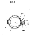
- Fig. 8 die Draufsicht auf einen Schmelzofen mit Erkerteil
- Der metallurgische Schmelzofen für die Verfahrensstufen der ersten Verfahrensalternative weist an der Ofenwanne 1 im Erkerteil 2 an der Unterseite das Verschlußorgan 3 auf, das z.B. aus einer anlegbaren Verschlußkappe bestehen kann. Die Abstichöffnung 4 Ist während des Schmelzvorganges mit einer Füllmasse gefüllt und schützt das Verschlußorgan 3 vor dem Einfluß der Metallschmelze, die, sofern aus Stahl bestehend, eine Temperatur von über 1.500°C aufweist. In dieser Verfahrensphase reicht die Stahlschmelze 5 mit der Restschlackenschicht 6 knapp unter die wassergekühlte Wandfläche 7 und berührt lediglich die feuerfeste Wandfläche 8 aus feuerfesten Mauerwerkssteinen. Für die Entfernung der Hauptschlacke ist die Scflackenabstichöffnung 9 vorgesehen. Der Schmelzofen ist mittels einer weiter nicht dargestellten Kippvorrichtung kippbar und mit einem Kippantrieb versehen, der ein feinstufiges Kippen oder alternativ ein kontinuierliches Kippen gestattet.
- Das Oberflächenverhältnis der wassergekühlten Wandfläche 7 und der Feuerfestwandfläche 8 beträgt, wie gezeichnet, etwa 7 : 1. Nachdem das Verschlußorgan 3 geöffnet ist (Fig. 2) erreicht der Schmelzofen eine Kippstellung von ca. 5°, wodurch eine ausreichend große Schmelzbadtiefe über der Abstichöffnung 4 vorhanden ist, was Potentialwirbel vermeidet. Der Gießstrahl 10 verläßt nahezu in laminarer Strömung das geöffnete Verchl ußorgan 3. Danach erfolgt ein in kleineren Stufen ausgeführtes oder kontinuierliches Kippen (Fig. 3) bis in eine Kipplage von ca. 8° bis 12°, falls erforderlich. Die Schmel zbadtiefe über der Abstichöffnung 4 reicht noch aus, um Potentialwirbel zu vermeiden. Für den Fall, daß in der letzten Phase solche Potentialwirbelfäden auftreten, verbrauchen diese ihre Energie an den Wänden des trapezförmigen Erkerteils (Fig. 8). Die letzte Phase (Fig. 4) besteht darin, das Schmelzgefäß negativ zu kippen. Während dieses Zurückkippens gelangt die Schlacke von der Abstichöffnung 4 weg und gleitet meist zurück in die Ofenwanne 1. Der verbleibende Metallschmel zensumpf und die Schlacke werden für die nachfolgende Charge genutzt.
- Die Verfahrensstufen der zweiten Verfahrensalternative werden anhand der Fig. 5 bis 8 beschrieben. Das Oberflächenverhältnis der wassergekühlten Wandfläche 7 zur feuerfesten Wandfläche 8 beträgt hier etwa 9 : 1, was ermöglicht wird, weil der Schmelzofen in erster Phase lotrecht steht (Fig. 5). Die Restschlackenschicht 6 wird in der ersten Phase mit Kalk abgesteift, so daß die Schlacke wie eine feste Decke wirkt. Nachdem das Verschlußorgan 3 in zweiter Phase geöffnet wird, strömt die Metallschmelze mittig aus der Ofenwanne 1 als Gießstrahl 10 mit annähernd laminarer Strömung in ein (nicht näher gezeigtes), etwa 1 m tiefer befindliches Gefäß. Die Ofenwanne 1 Ist muldenförmig gestaltet, und ein Erkerteil fehlt hier völlig.
- Bei kritisch werdender Schmelzbadtiefe (ca. 200 bis 400 mm über dem Gefäßboden) ist ein Potentialwirbel 11 nicht mehr auszuschließen (Fig. 6). Die Wirkung des Potentialwirbelfadens kommt jedoch in der abgesteiften Restschlackenschicht 6 nicht zur Geltung. Nachdem die Stahlschmelze 5 ausgelaufen ist (Fig. 7), setzt sich die Restschlackenschicht 6 auf dem Boden der Ofenwanne 1 ab. In dieser letzten Phase durchströmt nur ein geringer Teil der Schlacke die Abstichöffnung 4. Dieser Teil der Schlacke ist auch deshalb gering, weil der Großteil der Schlacke vor dem Abstich entfernt wird, so daß in der Phase gemäß Fig. 6 die Restschlackenschicht nur noch sehr dünn ist und als Restschlacke nur noch einen geringen Volumenanteil einnimmt.
- Der metallurgische Schmelzofen gemäß Fig. 8 weist den Erkerteil 2 auf, dessen innere Begrenzungswand 12 trapezförmig verläuft. Die Trapezschenkelwände 13a und 13b verlaufen In Richtung Schmelzraum 14 tangential zu dem kreisförmigen bzw. ovalförmigen Ofeninnenraum 15. Die Abstichöffnung 4 ist auf der Trapezachse 16 angeordnet. Zusätzlich zu der Abstichöffnung 4 im Erkerteil 2 kann auch noch ein Abstichloch 4a in der Mittelachse 17 des Ofeninnenraums 15 vorgesehen sein.
Claims (7)
daß bei einem Oberflächenverhältnis von wassergekühlter Wand- fläche/feuerfester Wandfläche von 6 : 1 bis 9 : 1 der Schmelzofen während des Abstechens lediglich von 0° bis maximal +15° bzw. von 0° bis maximal -6° gekippt wird, daß im Bereich des Verschlußorgans fortwährend eine unkritische Schmelzbadtiefe beim Vorwärtskippen des Schmel zofens aufrechterhalten wird und daß gegen Ende des Abstechens die auf der restlichen Metallschmelze schwimmende Schlacke durch Zurückkippen des Schmelzofens aus dem Bereich des Verschl ußorgans verlagert wird.
daß bei einen Oberflächenverhältnis von wassergekühlter Wandfläche/feuerfester Wandfläche von 7 : 1 bis 10 : 1 der Schmelzofen während des Abstechens in lotrechter Position verbleibt, daß die Schlacke durch Zugabe von Absteifmittel zähflüssig gemacht wird, daß im Bereich des Verschlußorgans fortwährend die jeweils größte Schmelzbadtiefe aufrechterhalten wird und daß gegen Ende des Abstechens die nach einem Abschlackvorgang vorhandene Rest-schlacke auf dem Gefäßboden abgelagert wird.
dadurch gekennzeichnet,
daß bei einer jeweils um ca. 20°C gegenüber der qualitäts- bzw. nachbehandlungsabhängigen Abstichtemperatur verminderten Abstichtemperatur die Metallschmelze abgelassen wird.
daß das unter dem Schmelzofen befindliche Gefäß bis maximal 1 m des lotrechten Abstandes, gemessen vom Verschlußorgan bis zum Gefäßrand, eingestellt wird.
dadurch gekennzeichnet,
daß der Erkerteil (2) mit seiner inneren Begrenzungswand (12) im Grundriß (Fig. 8) angenähert trapezförmig ausgebildet ist, daß die Trapezschenkelwände (13a,13b) im Bereich der dem Schmelzraum (14) zugewandten Seite zu den kreisförmigen bzw. ovalförmigen Ofeninnenraum (15) jeweils tangential verlaufen und daß die Abstichöffnung (4) auf der Trapezachse (16) angeordnet ist.
dadurch gekennzeichnet,
daß der Erkerteil (2) mit seiner inneren Begrenzungswand (12) im Grundriß rechteckförmig ausgebildet ist, daß die Seitenwände (13a,13b) im Bereich der dem Schmelzraum (14) zugewandten Seite zu dem kreisförmigen bzw. ovalförmigen Ofeninnenraum (15) als parallele Sekanten verlaufen und daß die Abstichöffnung (4) mittig zwischen den Sekanten angeordnet ist.
dadurch gekennzeichnet,
daß entweder nur das Abstichloch (4) im Erkerteil (2) oder nur das Abstichloch (4a) in der Mittelachse (17) des Ofeninnenraums (15) vorgesehen sind oder daß sowohl im Ofeninnenraum (15) als auch im Erkerteil (2) jeweils ein gesondertes Abstichloch vorgesehen sind.
Priority Applications (3)
| Application Number | Priority Date | Filing Date | Title |
|---|---|---|---|
| DE8383105858T DE3373014D1 (en) | 1983-06-15 | 1983-06-15 | Process for operating a metallurgical melting-furnace, and metallurgical melting-furnace |
| AT83105858T ATE28930T1 (de) | 1983-06-15 | 1983-06-15 | Verfahren zum betreiben eines metallurgischen schmelzofens und metallurgischer schmelzofen. |
| EP83105858A EP0128965B1 (de) | 1983-06-15 | 1983-06-15 | Verfahren zum Betreiben eines metallurgischen Schmelzofens und metallurgischer Schmelzofen |
Applications Claiming Priority (1)
| Application Number | Priority Date | Filing Date | Title |
|---|---|---|---|
| EP83105858A EP0128965B1 (de) | 1983-06-15 | 1983-06-15 | Verfahren zum Betreiben eines metallurgischen Schmelzofens und metallurgischer Schmelzofen |
Publications (2)
| Publication Number | Publication Date |
|---|---|
| EP0128965A1 true EP0128965A1 (de) | 1984-12-27 |
| EP0128965B1 EP0128965B1 (de) | 1987-08-12 |
Family
ID=8190526
Family Applications (1)
| Application Number | Title | Priority Date | Filing Date |
|---|---|---|---|
| EP83105858A Expired EP0128965B1 (de) | 1983-06-15 | 1983-06-15 | Verfahren zum Betreiben eines metallurgischen Schmelzofens und metallurgischer Schmelzofen |
Country Status (3)
| Country | Link |
|---|---|
| EP (1) | EP0128965B1 (de) |
| AT (1) | ATE28930T1 (de) |
| DE (1) | DE3373014D1 (de) |
Cited By (6)
| Publication number | Priority date | Publication date | Assignee | Title |
|---|---|---|---|---|
| FR2580092A1 (de) * | 1985-04-05 | 1986-10-10 | Vallourec | |
| EP0216187A2 (de) * | 1985-09-21 | 1987-04-01 | Fuchs Systemtechnik GmbH | Ofengefäss eines metallurgischen Ofens, insbesondere eines Lichtbogenofens |
| GB2243813A (en) * | 1990-05-11 | 1991-11-13 | Trw Cam Gears Ltd | Hydraulic power assisted steering |
| EP0495723A1 (de) * | 1991-01-18 | 1992-07-22 | Isover Saint-Gobain | Verfahren und Vorrichtung zum Herstellen von Mineralfasern |
| FR2671792A1 (fr) * | 1991-01-18 | 1992-07-24 | Saint Gobain Isover | Procede et dispositif d'obtention de fibres minerales. |
| DE102005024924A1 (de) * | 2005-05-23 | 2006-12-07 | Strikowestofen Gmbh | Schmelz- oder Warmhalteofen |
Citations (5)
| Publication number | Priority date | Publication date | Assignee | Title |
|---|---|---|---|---|
| DE1804007A1 (de) * | 1968-10-19 | 1970-06-04 | Demag Elektrometallurgie Gmbh | Kippbarer Elektro-Schmelzofen,insbesondere Lichtbogenofen,mit einem feuerfest ausgekleideten Auslauf |
| FR2218398A1 (en) * | 1973-02-21 | 1974-09-13 | Siderurgie Fse Inst Rech | Electric arc furnace - for treating metallised materials allows casting in any posn. |
| DE2921702A1 (de) * | 1979-05-29 | 1980-12-11 | Demag Ag Mannesmann | Elektro-metallschmelzofen |
| DE2944269A1 (de) * | 1979-11-02 | 1981-05-07 | Mannesmann Demag Ag, 4100 Duisburg | Ofengefaess eines lichtbogenofens |
| DE3102499A1 (de) * | 1981-01-27 | 1982-08-05 | Mannesmann AG, 4000 Düsseldorf | "stahlschmelzanlage" |
-
1983
- 1983-06-15 DE DE8383105858T patent/DE3373014D1/de not_active Expired
- 1983-06-15 AT AT83105858T patent/ATE28930T1/de not_active IP Right Cessation
- 1983-06-15 EP EP83105858A patent/EP0128965B1/de not_active Expired
Patent Citations (5)
| Publication number | Priority date | Publication date | Assignee | Title |
|---|---|---|---|---|
| DE1804007A1 (de) * | 1968-10-19 | 1970-06-04 | Demag Elektrometallurgie Gmbh | Kippbarer Elektro-Schmelzofen,insbesondere Lichtbogenofen,mit einem feuerfest ausgekleideten Auslauf |
| FR2218398A1 (en) * | 1973-02-21 | 1974-09-13 | Siderurgie Fse Inst Rech | Electric arc furnace - for treating metallised materials allows casting in any posn. |
| DE2921702A1 (de) * | 1979-05-29 | 1980-12-11 | Demag Ag Mannesmann | Elektro-metallschmelzofen |
| DE2944269A1 (de) * | 1979-11-02 | 1981-05-07 | Mannesmann Demag Ag, 4100 Duisburg | Ofengefaess eines lichtbogenofens |
| DE3102499A1 (de) * | 1981-01-27 | 1982-08-05 | Mannesmann AG, 4000 Düsseldorf | "stahlschmelzanlage" |
Cited By (13)
| Publication number | Priority date | Publication date | Assignee | Title |
|---|---|---|---|---|
| FR2580092A1 (de) * | 1985-04-05 | 1986-10-10 | Vallourec | |
| EP0201379A1 (de) * | 1985-04-05 | 1986-11-12 | VALLOUREC Société Anonyme dite. | Verfahren und System zur Steuerung des Kippvorgangs eines Behälters mit flüssigem Metall |
| EP0216187A2 (de) * | 1985-09-21 | 1987-04-01 | Fuchs Systemtechnik GmbH | Ofengefäss eines metallurgischen Ofens, insbesondere eines Lichtbogenofens |
| EP0216187A3 (en) * | 1985-09-21 | 1988-01-20 | Fuchs Systemtechnik Gmbh | Metallurgical-furnace vessel, in particular of an arc furnace |
| GB2243813A (en) * | 1990-05-11 | 1991-11-13 | Trw Cam Gears Ltd | Hydraulic power assisted steering |
| GB2243813B (en) * | 1990-05-11 | 1994-01-26 | Trw Cam Gears Ltd | A vehicle power assisted steering system |
| FR2671792A1 (fr) * | 1991-01-18 | 1992-07-24 | Saint Gobain Isover | Procede et dispositif d'obtention de fibres minerales. |
| EP0495723A1 (de) * | 1991-01-18 | 1992-07-22 | Isover Saint-Gobain | Verfahren und Vorrichtung zum Herstellen von Mineralfasern |
| US5338329A (en) * | 1991-01-18 | 1994-08-16 | Isover Saint-Gobain | Process and device for obtaining mineral fibers |
| TR26879A (tr) * | 1991-01-18 | 1994-08-22 | Saint Gobain Isover | Mineral lif elde etmek icin yöntem ve düzenek |
| DE102005024924A1 (de) * | 2005-05-23 | 2006-12-07 | Strikowestofen Gmbh | Schmelz- oder Warmhalteofen |
| DE102005024924B4 (de) * | 2005-05-23 | 2007-06-14 | Strikowestofen Gmbh | Schmelz- oder Warmhalteofen |
| DE102005024924B8 (de) * | 2005-05-23 | 2007-10-25 | Strikowestofen Gmbh | Schmelz- oder Warmhalteofen |
Also Published As
| Publication number | Publication date |
|---|---|
| ATE28930T1 (de) | 1987-08-15 |
| EP0128965B1 (de) | 1987-08-12 |
| DE3373014D1 (en) | 1987-09-17 |
Similar Documents
| Publication | Publication Date | Title |
|---|---|---|
| DE3321576A1 (de) | Verfahren zum betreiben eines metallurgischen schmelzofens und metallurgischer schmelzofen | |
| DE2944269C3 (de) | Ofengefäß eines kippbaren Lichtbogenofens | |
| DE3241987C2 (de) | Kippbarer Lichtbogenofen | |
| DE2256269A1 (de) | Metallerzeugungsanlage mit mindestens einem kippbaren konverter | |
| DE2406480A1 (de) | Verfahren zum raffinieren von stahl | |
| EP0128965B1 (de) | Verfahren zum Betreiben eines metallurgischen Schmelzofens und metallurgischer Schmelzofen | |
| EP0180741A1 (de) | Verfahren und Vorrichtung zum Halten oder Erhöhen der Temperatur einer Metallschmelze | |
| DE2921702C2 (de) | Elektro-Metallschmelzofen mit Bodenabstich | |
| EP0160185B1 (de) | Kippbares metallurgisches Ofengefäss | |
| EP0470223A1 (de) | Metallurgisches aggregat | |
| EP0799323B1 (de) | Kippbares metallurgisches aggregat bestehend aus mehreren gefässen | |
| DE3327671C2 (de) | Einrichtung zum weitestgehend schlackenfreien Abstechen von Metalschmelzen, insbesondere von Stahlschmelzen, aus metallurgischen Gefäßen | |
| DE2450495C2 (de) | Einrichtung zur Stahlerzeugung | |
| DE8317437U1 (de) | Metallurgischer Schmelzofen | |
| DE2407676A1 (de) | Lichtbogenofen zum schmelzen und frischen von metallischen feststoffen | |
| EP0216187B1 (de) | Ofengefäss eines metallurgischen Ofens, insbesondere eines Lichtbogenofens | |
| EP1432834B1 (de) | Verfahren zum betreiben eines kippbaren lichtbogenofens mit angebauten erker zum abstechen der schmelze | |
| EP0321861A2 (de) | Kippbares metallurgisches Gefäss | |
| DE1207554B (de) | Wahlweise um zwei verschiedene Kippachsen kippbarer rinnenloser Induktions-Tiegelofen | |
| DE2062114A1 (en) | Pure, killed steel mfr - for deep-drawn quality sheet steel | |
| DE1804007A1 (de) | Kippbarer Elektro-Schmelzofen,insbesondere Lichtbogenofen,mit einem feuerfest ausgekleideten Auslauf | |
| DE2452611A1 (de) | Verfahren und vorrichtung zum raffinieren und/oder zum frischen einer metallschmelze | |
| JPS62254965A (ja) | 注湯取鍋 | |
| DE2240974C3 (de) | Kokille für Elektroschlacke-Umschmelzanlagen | |
| DE3612613C1 (de) | Rinne zum kontinuierlichen Raffinieren von Metallschmelzen, insbesondere von Roheisenschmelzen |
Legal Events
| Date | Code | Title | Description |
|---|---|---|---|
| PUAI | Public reference made under article 153(3) epc to a published international application that has entered the european phase |
Free format text: ORIGINAL CODE: 0009012 |
|
| 17P | Request for examination filed |
Effective date: 19840724 |
|
| AK | Designated contracting states |
Designated state(s): AT BE CH DE FR GB IT LI LU NL SE |
|
| 17Q | First examination report despatched |
Effective date: 19860204 |
|
| D17Q | First examination report despatched (deleted) | ||
| GRAA | (expected) grant |
Free format text: ORIGINAL CODE: 0009210 |
|
| AK | Designated contracting states |
Kind code of ref document: B1 Designated state(s): AT BE CH DE FR GB IT LI LU NL SE |
|
| REF | Corresponds to: |
Ref document number: 28930 Country of ref document: AT Date of ref document: 19870815 Kind code of ref document: T |
|
| REF | Corresponds to: |
Ref document number: 3373014 Country of ref document: DE Date of ref document: 19870917 |
|
| ITF | It: translation for a ep patent filed |
Owner name: MODIANO & ASSOCIATI S.R.L. |
|
| ET | Fr: translation filed | ||
| PLBI | Opposition filed |
Free format text: ORIGINAL CODE: 0009260 |
|
| PLBI | Opposition filed |
Free format text: ORIGINAL CODE: 0009260 |
|
| PLBI | Opposition filed |
Free format text: ORIGINAL CODE: 0009260 |
|
| 26 | Opposition filed |
Opponent name: DANIELI & CO. OFFICINE MECCANICHE SPA Effective date: 19880420 |
|
| 26 | Opposition filed |
Opponent name: ASEA BROWN BOVERI AG Effective date: 19880506 Opponent name: DANIELI & CO. OFFICINE MECCANICHE SPA Effective date: 19880420 |
|
| 26 | Opposition filed |
Opponent name: FRIED. KRUPP GMBH Effective date: 19880513 Opponent name: MAN GUTEHOFFNUNGSHUETTE GMBH Effective date: 19880510 Opponent name: ASEA BROWN BOVERI AG Effective date: 19880506 Opponent name: DANIELI & CO. OFFICINE MECCANICHE SPA Effective date: 19880420 |
|
| NLR1 | Nl: opposition has been filed with the epo |
Opponent name: ASEA BROWN BOVERI AG Opponent name: DANIELI & CO. OFFICINE MECCANICHE SPA |
|
| NLR1 | Nl: opposition has been filed with the epo |
Opponent name: FRIED. KRUPP GMBH Opponent name: MAN GUTEHOFFNUNGSHUETTE GMBH |
|
| PLAB | Opposition data, opponent's data or that of the opponent's representative modified |
Free format text: ORIGINAL CODE: 0009299OPPO |
|
| R26 | Opposition filed (corrected) |
Opponent name: DANIELI & C. OFFICINE MECCANICHE SPA * 880506 ASE Effective date: 19880420 |
|
| PLAB | Opposition data, opponent's data or that of the opponent's representative modified |
Free format text: ORIGINAL CODE: 0009299OPPO |
|
| R26 | Opposition filed (corrected) |
Opponent name: DANIELI & C. OFFICINE MECCANICHE SPA * 880506 ASE Effective date: 19880420 |
|
| NLXE | Nl: other communications concerning ep-patents (part 3 heading xe) |
Free format text: IN PAT.BUL.17/88,CORR.:MAN GUTEHOFFNUNGSHUETTE AG. |
|
| PGFP | Annual fee paid to national office [announced via postgrant information from national office to epo] |
Ref country code: GB Payment date: 19920507 Year of fee payment: 10 |
|
| PGFP | Annual fee paid to national office [announced via postgrant information from national office to epo] |
Ref country code: CH Payment date: 19920518 Year of fee payment: 10 Ref country code: BE Payment date: 19920518 Year of fee payment: 10 |
|
| PGFP | Annual fee paid to national office [announced via postgrant information from national office to epo] |
Ref country code: FR Payment date: 19920520 Year of fee payment: 10 |
|
| PGFP | Annual fee paid to national office [announced via postgrant information from national office to epo] |
Ref country code: SE Payment date: 19920525 Year of fee payment: 10 |
|
| PGFP | Annual fee paid to national office [announced via postgrant information from national office to epo] |
Ref country code: LU Payment date: 19920527 Year of fee payment: 10 |
|
| PGFP | Annual fee paid to national office [announced via postgrant information from national office to epo] |
Ref country code: AT Payment date: 19920529 Year of fee payment: 10 |
|
| ITTA | It: last paid annual fee | ||
| PGFP | Annual fee paid to national office [announced via postgrant information from national office to epo] |
Ref country code: NL Payment date: 19920630 Year of fee payment: 10 |
|
| EPTA | Lu: last paid annual fee | ||
| PG25 | Lapsed in a contracting state [announced via postgrant information from national office to epo] |
Ref country code: LU Free format text: LAPSE BECAUSE OF NON-PAYMENT OF DUE FEES Effective date: 19930615 Ref country code: GB Effective date: 19930615 Ref country code: AT Effective date: 19930615 |
|
| PG25 | Lapsed in a contracting state [announced via postgrant information from national office to epo] |
Ref country code: SE Effective date: 19930616 |
|
| PG25 | Lapsed in a contracting state [announced via postgrant information from national office to epo] |
Ref country code: LI Free format text: LAPSE BECAUSE OF NON-PAYMENT OF DUE FEES Effective date: 19930630 Ref country code: CH Free format text: LAPSE BECAUSE OF NON-PAYMENT OF DUE FEES Effective date: 19930630 Ref country code: BE Effective date: 19930630 |
|
| BERE | Be: lapsed |
Owner name: MANNESMANN A.G. Effective date: 19930630 |
|
| PG25 | Lapsed in a contracting state [announced via postgrant information from national office to epo] |
Ref country code: NL Effective date: 19940101 |
|
| GBPC | Gb: european patent ceased through non-payment of renewal fee |
Effective date: 19930615 |
|
| NLV4 | Nl: lapsed or anulled due to non-payment of the annual fee | ||
| PG25 | Lapsed in a contracting state [announced via postgrant information from national office to epo] |
Ref country code: FR Effective date: 19940228 |
|
| REG | Reference to a national code |
Ref country code: CH Ref legal event code: PL |
|
| REG | Reference to a national code |
Ref country code: FR Ref legal event code: ST |
|
| PGFP | Annual fee paid to national office [announced via postgrant information from national office to epo] |
Ref country code: DE Payment date: 19940726 Year of fee payment: 12 |
|
| EUG | Se: european patent has lapsed |
Ref document number: 83105858.1 Effective date: 19940110 |
|
| RDAG | Patent revoked |
Free format text: ORIGINAL CODE: 0009271 |
|
| STAA | Information on the status of an ep patent application or granted ep patent |
Free format text: STATUS: PATENT REVOKED |
|
| 27W | Patent revoked |
Effective date: 19950606 |
|
| APAH | Appeal reference modified |
Free format text: ORIGINAL CODE: EPIDOSCREFNO |