EP0128372B1 - Dispositif de fermeture d'un battant d'une porte, fenêtre ou similaire à deux battants - Google Patents
Dispositif de fermeture d'un battant d'une porte, fenêtre ou similaire à deux battants Download PDFInfo
- Publication number
- EP0128372B1 EP0128372B1 EP84105341A EP84105341A EP0128372B1 EP 0128372 B1 EP0128372 B1 EP 0128372B1 EP 84105341 A EP84105341 A EP 84105341A EP 84105341 A EP84105341 A EP 84105341A EP 0128372 B1 EP0128372 B1 EP 0128372B1
- Authority
- EP
- European Patent Office
- Prior art keywords
- cover rail
- drive rod
- pinion
- reversing device
- faceplate
- Prior art date
- Legal status (The legal status is an assumption and is not a legal conclusion. Google has not performed a legal analysis and makes no representation as to the accuracy of the status listed.)
- Expired
Links
Images
Classifications
-
- E—FIXED CONSTRUCTIONS
- E05—LOCKS; KEYS; WINDOW OR DOOR FITTINGS; SAFES
- E05C—BOLTS OR FASTENING DEVICES FOR WINGS, SPECIALLY FOR DOORS OR WINDOWS
- E05C7/00—Fastening devices specially adapted for two wings
- E05C7/04—Fastening devices specially adapted for two wings for wings which abut when closed
Definitions
- the invention relates to a device for locking the secondary wing of a double-leaf window, a door or the like. Without a fixed middle joint with the upper and lower crossbar or the like.
- the main leaf is usually equipped as a rotating leaf, but preferably as a tilt-and-turn leaf with normal fittings.
- the secondary wing must also be locked when the wing I is open or tilted. It is also required that the secondary wing can be rotated so that its outer surface is accessible for cleaning.
- FR-A-2 237484 discloses a device of the type described in the introduction. Your two drive rods and the faceplate can be easily accommodated in the conventionally designed and dimensioned receiving groove. Said reversing means not described in detail, by means of which it causes the actuation of the drive rods, and ultimately the latches to the side wing requires due to their training and dimensioning of a fairly large recess in mosachsfernen side wing-side member, thus for example in a solid longitudinal spar a large Ausfrä- sun g . It reaches up to the glass holding groove.
- the receiving grooves for solid frames are generally of a certain shape and size and for this reason the cross-sections of the drive rod and faceplate of most of the manufacturers of window lock fittings used today are similar to those of Standards, standardized. This also enables smaller workshops to mill such grooves in massive spars without having to keep a large number of cutter sets available.
- the object of the invention is therefore to further develop a device of the type described in the introduction in such a way that cutouts and the like in the frame spar are unnecessary.
- the characterizing features of claim 1 are proposed in a generic device. Accordingly, the reversing device is located exclusively and completely in the receiving groove of the secondary wing longitudinal spar remote from the rotary axis.
- the reversing device of this device is dimensioned and designed so that it can be accommodated in the comparatively small groove which already accommodates the drive rods.
- the two bolts can still be unlocked or locked centrally from a single point.
- the handle can be placed on the wing so that it is easily accessible even by smaller people. Because of the good accessibility, the operation as such is also simplified.
- these bolts also work in a known manner, each with a striking plate or the like on the upper or lower cross member of the fixed frame.
- the striking plate can be omitted and the locking can take place directly in a corresponding hole or receptacle of the fixed frame.
- the receiving groove which as I said is a general My usual dimensioning, as used for conventional window locks, is generally available for profile frames. In the case of a wooden window, any processor can continue to create it in a known manner using the tools available to him.
- the drive rods are mounted on the faceplate to be longitudinally displaceable.
- the faceplate and the drive rods with the reversing device can be combined to form a tradable unit, which is mounted overall on the secondary wing or its receiving groove.
- the faceplate also protects the underlying parts in a known manner, in particular also the longitudinal guides for the drive rods and the reversing device.
- the faceplate offers a clean optical closure of the receiving groove, which in a known manner has a support shoulder for the left and right edge of the faceplate on both sides at its outlet end.
- Another variant of the invention is characterized by at least one guide piece of the faceplate for each drive rod, which passes through an elongated hole or the like of the drive rod with a foot held on the faceplate, and the thickened head of which is assigned to the face of the drive rod facing away from the faceplate .
- This guide piece can, for example, have an essentially T-shaped shape, in which case the T-crosspiece forms the thickened head. Its width can roughly correspond to that of the drive rods.
- the length of the elongated hole penetrated by the foot or T-longitudinal web essentially corresponds to the maximum possible stroke or displacement path of the bolt.
- Each drive rod is thus held transversely to its plane on the one hand by the thickened head and on the other hand by the faceplate.
- each guide piece also very advantageously forms a spacer element for the drive rod and is supported on the base of the groove. Accordingly, its thickness depends on the groove depth and the total thickness of the drive rod and faceplate, including the necessary play for the drive rod.
- the guide piece has a fastening bore which extends transversely to the longitudinal axis of the drive rod and through which a fastening means, for example a screw, can be inserted, the inner end of which is screwed into the wing spar.
- a fastening means for example a screw
- This screw can be tightened without disadvantage, which then holds this device securely. It also follows from this that the number of guide pieces also depends on the overall length of the device. In the case of a window, two guide pieces for the upper and lower drive rod, for example, may be sufficient.
- the rotary member is a pinion
- the two pinion-side ends of the drive rods are designed as toothed racks or the like or are each connected to a toothed rack; wherein the racks are coupled opposite to each other with the pinion and the pinion is in drive connection with the handle.
- the pinion and each rack or a correspondingly perforated rod guarantee an exact, form-fitting coupling and a safe working method.
- they are simple components.
- the toothed racks can, for example, be molded directly onto the inner ends of the toothed racks. Stamping of the teeth is particularly useful here. If at the same time the bolts are molded onto the drive rod, this contributes very significantly to the low manufacturing costs of the individual parts and also the costs for assembling the entire device.
- a shaft of the handle engages in an axial bore of the pinion, the connection is in particular designed as a positive connection.
- the axial bore extends perpendicular to the longitudinal axis of the faceplate or drive rods and also perpendicular to the faceplate plane.
- the shaft is particularly expedient for the shaft to be designed as a polygonal shaft, at least in the area of the positive connection, and for it to penetrate a bore of the faceplate to the outside, the outer shaft end carrying a flat, approximately air gap-thick handle. With the help of the latter, the shaft can be rotated both clockwise and counterclockwise, preferably a 180 ° rotation for locking and unlocking is provided.
- the small thickness of the handle allows it to be left constantly on the shaft or the shaft in the pinion bore. Nevertheless, the shaft can be designed to be removable so that it can be removed together with the handle, thereby preventing an undesired actuation of this device.
- This handle can be, for example, a one-armed lever.
- Another variant of the invention is characterized by a locking member of the pinion for the inserted shaft end of the handle, which is designed in particular as a spring ring.
- the latter is expediently located in the region of the insertion opening of the pinion, so that it can hold the shaft even when it is not fully inserted into the pinion's receiving bore.
- a spring washer there is a corresponding receiving groove in the outward-pointing pinion end.
- each toothed rack or the like runs in a very advantageous manner approximately perpendicular to the plane of the drive rod and faceplate and also the pinion axis extends perpendicular to the faceplate plane and perpendicular to the longitudinal axis of the faceplate.
- the teeth of the Show racks against the inner surface of the faceplate and each rack is made in one piece with its drive rod. So even though the drive rod and the faceplate are made of flat material, this " upright arrangement" of the toothed rack with respect to the faceplate can be achieved, for example, by tilting the drive rod end designed as a rack by 90 °. At the same time, there is a sufficiently wide space between these two racks for receiving the Ritzels, which, as I said, lies between the two drive rods.
- a preferred embodiment of the invention provides that the pinion is rotatably mounted with a first pin-shaped projection in a bore of the faceplate and with a second pin-shaped extension coaxial therewith in a housing of the reversing device fastened to the faceplate.
- This housing can be made very compact and essentially arranged between the toothed racks, so that the depth of the device in this area can be kept extremely small, which enables assembly in the conventional, comparatively small groove, without requiring additional cutouts and the like .
- the housing it is particularly expedient for the housing to overlap the toothed rack back, preferably with lateral shoulders, the thickness of this back being reduced, in particular in a shoulder-like manner.
- the latter feature makes it possible to make the housing particularly narrow in the direction of the width of the faceplate, in particular to choose this width so that it is not greater than the total width of the pinion with the two racks engaging on the left and right.
- the side lugs ensure that the toothed rack and pinion always mesh securely.
- Another embodiment of the invention provides that the housing of the reversing device is riveted to the faceplate by means of in particular two molded rivets.
- This device also contributes to the simple, quick and safe installation of this device. To a certain extent from the back, these rivet attachments of the housing are inserted into associated rivet holes in the faceplate and subsequently permanently deformed. It is advantageous here if these bores of the faceplate are chamfered on the outside.
- the molded rivets are hollow rivets in a particularly expedient manner and at the same time they each form a fastening bore for the faceplate on the secondary wing. Otherwise, you can choose the thickness of the housing so that the housing can also take on the task of a spacer.
- each bolt in the unlocked position is flush with the associated faceplate end. This makes it possible to cut the faceplate and the bolt to length together, thereby precisely adapting the device to the respective wing height. Expediently, when the bar is cut to length, the corners will be rounded off or beveled somewhat.
- the faceplate is held at its upper and / or lower end by means of one or each of a guide piece which has an opening for the bolt. This means that this end, calculated from the last guide piece, can be made particularly long in order to achieve a wide range of adjustment options.
- An advantageous development of the invention consists in that at least one locking plate and / or tilting locking plate or the like is attached to the faceplate for a locking and / or locking tilting fitting of the main wing directly or indirectly.
- the main wing can then be securely locked and unlocked with the latter when the secondary wing is closed and locked.
- the panels must be designed in such a way that the corresponding elements of the main wing fittings can interact in the manner intended. This applies to both locking and unlocking, as well as switching from the closed to the tilt position and vice versa.
- Each striker plate or the like expediently has a fastening bore which is aligned with a fastening bore of the faceplate and preferably also of or one of the guide pieces for the drive rod.
- the locking plate can be manufactured separately and still be installed together with the faceplate in this area without additional assembly effort.
- a suitable anti-rotation device is provided in order to avoid a second fastening screw for the plate.
- Such an anti-rotation device can consist, for example, of one or two pin-hole connections. In particular, two adjacent pins are provided on the locking plate, which engage in corresponding bores or punched holes in the faceplate.
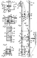
- the device according to the invention is installed in a two-leaf window, the right wing of which is seen from the inside and represents the main wing 1 and the left wing is the secondary wing 2, the main wing being rotatable and tiltable, while the secondary wing is only rotatably mounted in a fixed frame, not shown is.
- the main wing is turned and tilted in a known manner with a known fitting. Accordingly, the vertical spars 3 of the main wing 1 and 4 of the secondary wing 2 are located directly next to one another, the spars 3 and 4 being the spars of the wings in question, which are located away from their axes of rotation. As indicated in FIG.
- the wings can be made from solid material, for example wood, or constructed from profiles according to FIG. 2. In both types, cover strips are still provided to cover the gap space and for sealing in this window area.
- the cover strips 6 and 7 can, contrary to the illustration in FIG. 1, also consist of wood and be directly molded on or glued to it in a known manner.
- the cover strip 8 of the embodiment of FIG. 2 is, however, manufactured separately and mounted on the profile of the secondary wing.
- a receiving groove 9 or 10 is provided.
- these two grooves lie directly opposite one another.
- they are also opposite one another, but there is still the inner web 11 of the cover strip 8 between them.
- the cross-sectional shape and size of these receiving grooves correspond to the standard design customary here. For this reason, in the case of a frame made of solid bars, the groove can be created with the generally available tools. In the case of profiles made of plastic or aluminum or the like, the profiles do not deviate from conventional profiles in this respect.
- the bars 12 and 13 are each formed according to the invention by the free end of an upper drive rod 14 and a lower drive rod 15. Instead of the one-piece production of the drive rod and bolt, a separate production with subsequent connection can also take place. However, one-piece production is cheaper and simpler.
- the drive rods can be moved in opposite directions, i. H. at the same time the upper drive rod 14 moves upward in the direction of arrow 16 and the lower drive rod 15 moves downward in the direction of arrow 17.
- the arrows 16 and 17 symbolize the locking movement, while the unlocking movement naturally runs in the opposite direction. This locking and unlocking movement is achieved with the aid of a handle 18 and a reversing device 19 connected between the inner ends of the drive rods 14 and 15.
- the drive rods 14 and 15 are covered in the installed state by means of a face plate 20 and at the same time mounted longitudinally displaceably on this face plate. This is achieved with the aid of guide pieces 21.
- guide pieces 21 In the case of the exemplary embodiment, two guide pieces are provided for each drive rod.
- the guide pieces are fastened to the faceplate 20, for example riveted.
- Her foot 22 penetrates an elongated hole 23 of the associated drive rod 14 or 15. Accordingly, the drive rod is located between the faceplate 20 and a thickened head 24 of the guide piece 21.
- the latter has a T-shaped shape in the exemplary embodiment. So that the faceplate and the drive rods are held together with the help of the guide pieces 21.
- a fastening bore 25 extending transversely to the longitudinal axis of the drive rod is provided on each guide piece 21.
- a fastening element in particular a screw, which passes through the fastening bore 25 and is screwed, for example, into the material of the spar 4.
- the reversing device 19 is a rotary member which is in drive connection with the two drive rods 14, 15 and which is preferably designed as a pinion 28.
- the two pinion-side ends of the drive rods are designed as racks 29 and 30, respectively.
- This one-piece production of drive rod and rack is particularly inexpensive. Instead, the racks can also be manufactured separately and connected to the inner drive rod end.
- the pinion 28 is located between the two racks 29 and 30, ie the racks are coupled to the pinion opposite one another.
- the pinion 28 has an axial bore 31 into which a shaft 32 of the handle 18 can be inserted.
- the shaft 32 is designed as a polygonal shaft, at least in the insertion area, but preferably over its entire length. Accordingly, the axial bore 31 is a polygonal bore.
- the handle 33 of the handle 18 is assigned to the outer surface of the faceplate 20 or is located in the gap 5, it becomes particularly flat, ie. H. formed about gap air thick. Accordingly, the shaft 32 passes through a bore 34 of the faceplate 20. However, this bore 34 is expediently made somewhat larger, so that a pin-shaped extension of the pinion 28 can be stored therein.
- the pinion 28 has two such pin-shaped approaches.
- the first peg-shaped extension 36 penetrates the bore 34 of the faceplate 20, while the second conical extension 35, which projects coaxially but projects in the opposite direction, is rotatably mounted in a housing 37 of the reversing device 19 fastened to the faceplate 20.
- a securing member in particular a spring ring 38. It prevents the handle 28 from being inadvertently released. Nevertheless, the handle can be removed if desired.
- the housing 37 of the reversing device 19 is firmly connected to the faceplate 20 by means of two, in particular integrally formed, rivets 39 and 40. It is expedient to use hollow rivets.
- the corresponding bores of the faceplate 20 are correspondingly widened or chamfered towards the outside (FIG. 5). 6 overlaps the rack backs 41 and 42 in order to ensure a secure tooth engagement between the pinion 32 and the two racks 29 and 30. The thickness of this back is expediently reduced in steps. As a result, the width of the housing 37 does not exceed the total width of the pinion and racks.
- the molded rivets 39 and 40 are, as said, hollow rivets, and as a result, they also form fastening bores for the faceplate with the housing 37 held thereon on the vertical spar 4 of the secondary wing 2.
- the plane of the toothed racks 29 and 30 runs approximately perpendicular to the plane of the drive rod 14 and 15 and thus also to the plane of the faceplate 20. This is also clearly shown in FIG. 6 3 and 4 that the teeth of the toothed racks 29 and 30 point against the inner surface 43 of the faceplate 20. Due to the one-piece production of the rack and drive rod and these mutually perpendicular planes, the inner drive rod ends forming the rack are set at 90 °. The setting point is designated 44 in FIG. 4.
- each bolt 12 or 13 in the unlocked position runs flush with the associated faceplate end. This makes it possible to cut the bolts and the faceplate together in this position and bring them to the required exact size. If the distance of the faceplate end from the guide piece 21 or from the last guide piece is relatively large, it is expedient if the free faceplate end is held down by a joining piece 45. It has an opening 46 through which the bolt 12 or 13 can pass upwards or downwards. The tabs' 47 engages over the associated Stulpschienenende. The two guide pieces are inserted into the groove 10, and their U-shaped edge 48 engages over the upper and lower end of the groove.
- two locking plates 49 or a locking plate 49 and a tilting locking plate 50 are mounted on the outer surface of the faceplate 20, for example.
- these plates interlocking nails or corresponding elements of a locking and / or locking tilting fitting of conventional design of the main wing 1 interact.
- the closing plate 49 has a fastening bore 51 which is aligned with a fastening bore of the faceplate 20 and preferably with the fastening bore 25 of the associated guide piece 21.
- Two transversely arranged pin-hole connections ensure a non-rotatable mounting of the locking plate 49.
- the two pins 52 and 53 are formed on the locking plate, while the associated holes are on the faceplate.
- the tilt locking plate 50 has an approximately central mounting hole 54 which is located between two pins 55 and 56 arranged in the longitudinal direction for a corresponding pin-hole connection with the faceplate.
- the bore 54 in turn is aligned with a fastening bore 25 of a guide piece 21.
- the inner web 11 of the cover strip 8 overlaps the faceplate 20 of this device.
- the locking plate 49 and / or a tilting locking plate is not placed directly on the outside of the faceplate 20, but is indirectly attached to the faceplate by interposing this inner web 11.
Landscapes
- Engineering & Computer Science (AREA)
- Mechanical Engineering (AREA)
- Power-Operated Mechanisms For Wings (AREA)
- Hinges (AREA)
- Supports Or Holders For Household Use (AREA)
- Specific Sealing Or Ventilating Devices For Doors And Windows (AREA)
Claims (20)
Priority Applications (1)
| Application Number | Priority Date | Filing Date | Title |
|---|---|---|---|
| AT84105341T ATE29548T1 (de) | 1983-06-09 | 1984-05-11 | Vorrichtung zum verriegeln des nebenfluegels eines zweifluegeligen fensters, einer tuer od. dgl. |
Applications Claiming Priority (2)
| Application Number | Priority Date | Filing Date | Title |
|---|---|---|---|
| DE3320826 | 1983-06-09 | ||
| DE19833320826 DE3320826A1 (de) | 1983-06-09 | 1983-06-09 | Vorrichtung zum verriegeln des nebenfluegels eines zweifluegeligen fensters, einer tuer od. dgl. |
Publications (3)
| Publication Number | Publication Date |
|---|---|
| EP0128372A2 EP0128372A2 (fr) | 1984-12-19 |
| EP0128372A3 EP0128372A3 (en) | 1985-09-11 |
| EP0128372B1 true EP0128372B1 (fr) | 1987-09-09 |
Family
ID=6201035
Family Applications (1)
| Application Number | Title | Priority Date | Filing Date |
|---|---|---|---|
| EP84105341A Expired EP0128372B1 (fr) | 1983-06-09 | 1984-05-11 | Dispositif de fermeture d'un battant d'une porte, fenêtre ou similaire à deux battants |
Country Status (3)
| Country | Link |
|---|---|
| EP (1) | EP0128372B1 (fr) |
| AT (1) | ATE29548T1 (fr) |
| DE (1) | DE3320826A1 (fr) |
Cited By (1)
| Publication number | Priority date | Publication date | Assignee | Title |
|---|---|---|---|---|
| DE4218983A1 (de) * | 1992-06-10 | 1993-12-16 | Siegenia Frank Kg | Fenster, Tür oder dergleichen mit Beschlägen für den Einbau in abgestufte Profilnuten der Flügel |
Families Citing this family (4)
| Publication number | Priority date | Publication date | Assignee | Title |
|---|---|---|---|---|
| DE3718173A1 (de) * | 1987-05-29 | 1988-12-22 | Siegenia Frank Kg | Treibstangengetriebe fuer fenster, tueren od. dgl. |
| DE4112851C2 (de) * | 1991-04-19 | 1995-05-11 | Beschlaege Koch Gmbh & Co Kg | Dreh-Schiebe-Türe, insbesondere für Rollstuhlfahrer |
| GB2279988A (en) * | 1993-07-16 | 1995-01-18 | Heywood Williams Ltd | Securement of closures |
| FR2717527B1 (fr) * | 1994-03-17 | 1996-05-15 | Alcan France | Dispositif de verrouillage d'un vantail semi-fixe pour fenêtre à deux vantaux. |
Family Cites Families (9)
| Publication number | Priority date | Publication date | Assignee | Title |
|---|---|---|---|---|
| NL50117C (fr) * | ||||
| DE2107511A1 (de) * | 1971-02-17 | 1972-08-31 | Siegenia-Frank KG, 5900 Siegen-Kaan-Marienborn | Treibstangenbeschlag für Fenster, Türen od.dgl |
| DE7144431U (de) * | 1971-11-25 | 1972-02-17 | Notter E Kg | Verriegelungsvorrichtung für ein zweiflügeliges Fenster |
| FR2237484A5 (en) * | 1973-06-27 | 1975-02-07 | Ferco Usine Ferrures | Locking mechanism for double doors - has identical casement bolts on each door independently locked to frame |
| US3919808A (en) * | 1974-03-29 | 1975-11-18 | Donald F Simmons | Door structure |
| FR2365016A1 (fr) * | 1976-09-21 | 1978-04-14 | Ferco Int Usine Ferrures | Procede de mise a dimension d'au moins une extremite de cremone a tetiere et dispositif pour la fixation de cette extremite |
| DE7736841U1 (de) * | 1977-12-02 | 1978-03-23 | Siegenia-Frank Kg, 5900 Siegen | Treibstangenverschluss fuer den unterschlagenden fluegel von zweifluegeligen fenstern oder tueren ohne mittelpfosten |
| DE3242090C2 (de) * | 1981-11-25 | 1985-04-11 | Siegenia-Frank Kg, 5900 Siegen | Treibstangenverschluß zum Feststellen des unterschlagenden Flügels von zweiflügeligen Fenstern oder Türen ohne Mittelpfosten in der geschlossenen Stellung |
| DE3300976C2 (de) * | 1983-01-13 | 1989-03-16 | Geze Gmbh, 7250 Leonberg | Treibstangenbeschlag |
-
1983
- 1983-06-09 DE DE19833320826 patent/DE3320826A1/de not_active Withdrawn
-
1984
- 1984-05-11 AT AT84105341T patent/ATE29548T1/de not_active IP Right Cessation
- 1984-05-11 EP EP84105341A patent/EP0128372B1/fr not_active Expired
Cited By (2)
| Publication number | Priority date | Publication date | Assignee | Title |
|---|---|---|---|---|
| DE4218983A1 (de) * | 1992-06-10 | 1993-12-16 | Siegenia Frank Kg | Fenster, Tür oder dergleichen mit Beschlägen für den Einbau in abgestufte Profilnuten der Flügel |
| DE4218983C2 (de) * | 1992-06-10 | 1999-02-18 | Siegenia Frank Kg | Fenster, oder Tür mit Beschlägen für den Einbau in abgestufte Profilnuten der Flügel |
Also Published As
| Publication number | Publication date |
|---|---|
| DE3320826A1 (de) | 1984-12-13 |
| EP0128372A2 (fr) | 1984-12-19 |
| ATE29548T1 (de) | 1987-09-15 |
| EP0128372A3 (en) | 1985-09-11 |
Similar Documents
| Publication | Publication Date | Title |
|---|---|---|
| EP0283659B2 (fr) | Porte, fenêtre ou similaire dont au moins le battant est construit de profilés en métal ou en matière plastique | |
| EP0440986B1 (fr) | Crémone | |
| EP0492341B1 (fr) | Crémone pour fenêtre à deux volets, ou similaire | |
| DE69910481T2 (de) | Verriegelungsvorrichtung für einen Schiebeflügel | |
| EP0883723B1 (fr) | Kit de montage de ferrure a tige de manoeuvre | |
| DE3645256C2 (de) | Fenster- und Türbeschlag | |
| EP0440987B2 (fr) | Crémone | |
| EP2252751B1 (fr) | Ferrure de tige d entraînement pour une fenêtre ou une porte | |
| EP0128372B1 (fr) | Dispositif de fermeture d'un battant d'une porte, fenêtre ou similaire à deux battants | |
| EP0493689B1 (fr) | Tringlerie de commande pour fenêtres, portes ou similaires | |
| EP0002248B2 (fr) | Dispositif de fermeture avec des tringles de commande pour le battant à usage secondaire d'une fenêtre ou d'une porte à deux battants sans jambage du milieu | |
| DE19521601C1 (de) | Fenster, Tür oder dergleichen | |
| EP0844348B1 (fr) | Penture pour portes ou fenêtres | |
| DE4218983A1 (de) | Fenster, Tür oder dergleichen mit Beschlägen für den Einbau in abgestufte Profilnuten der Flügel | |
| EP1159502A1 (fr) | Fenetre ou porte | |
| EP0725202B1 (fr) | Armature pour portes ou fenêtres | |
| EP3018269B1 (fr) | Systeme de poignee pour une fenetre ou similaire et fenetre ou similaire dotee du systeme de poignee | |
| DE2461228A1 (de) | Verschlussvorrichtung fuer fenster, tueren oder dergleichen | |
| EP0667432B1 (fr) | Dispositif de verrouillage supplémentaire pour fenêtre ou similaires | |
| EP0280950B1 (fr) | Strip de fermeture pour porte, fenêtre ou similaire | |
| EP0733761A2 (fr) | Cadre de battant | |
| WO1993004253A1 (fr) | Porte de securite et dispositif de securite pour le montage dans une porte | |
| DE8426131U1 (de) | Profilrahmen fuer ein fenster, eine tuer od. dgl. mit einem getriebegriff od. dgl. | |
| DE3348356C2 (en) | Tilting window casement or door wing extending arm | |
| DE19504419C2 (de) | Treibstangenbeschlag |
Legal Events
| Date | Code | Title | Description |
|---|---|---|---|
| PUAI | Public reference made under article 153(3) epc to a published international application that has entered the european phase |
Free format text: ORIGINAL CODE: 0009012 |
|
| AK | Designated contracting states |
Designated state(s): AT BE CH FR GB IT LI NL |
|
| PUAL | Search report despatched |
Free format text: ORIGINAL CODE: 0009013 |
|
| AK | Designated contracting states |
Designated state(s): AT BE CH FR GB IT LI NL |
|
| 17P | Request for examination filed |
Effective date: 19850830 |
|
| 17Q | First examination report despatched |
Effective date: 19860319 |
|
| ITF | It: translation for a ep patent filed |
Owner name: DE DOMINICIS & MAYER S.R.L. |
|
| GRAA | (expected) grant |
Free format text: ORIGINAL CODE: 0009210 |
|
| AK | Designated contracting states |
Kind code of ref document: B1 Designated state(s): AT BE CH FR GB IT LI NL |
|
| REF | Corresponds to: |
Ref document number: 29548 Country of ref document: AT Date of ref document: 19870915 Kind code of ref document: T |
|
| ET | Fr: translation filed | ||
| GBT | Gb: translation of ep patent filed (gb section 77(6)(a)/1977) | ||
| PLBI | Opposition filed |
Free format text: ORIGINAL CODE: 0009260 |
|
| PLBI | Opposition filed |
Free format text: ORIGINAL CODE: 0009260 |
|
| 26 | Opposition filed |
Opponent name: SIEGENIA-FRANK KG Effective date: 19880527 |
|
| 26 | Opposition filed |
Opponent name: WILH. FRANK GMBH Effective date: 19880610 Opponent name: SIEGENIA-FRANK KG Effective date: 19880527 |
|
| NLR1 | Nl: opposition has been filed with the epo |
Opponent name: SIEGENIA-FRANK KG |
|
| NLR1 | Nl: opposition has been filed with the epo |
Opponent name: WILH. FRANK GMBH |
|
| PLBG | Opposition deemed not to have been filed |
Free format text: ORIGINAL CODE: 0009274 |
|
| 26D | Opposition deemed not to have been filed |
Opponent name: WILH. FRANK GMBH Effective date: 19880610 |
|
| RDAG | Patent revoked |
Free format text: ORIGINAL CODE: 0009271 |
|
| STAA | Information on the status of an ep patent application or granted ep patent |
Free format text: STATUS: PATENT REVOKED |
|
| NLXE | Nl: other communications concerning ep-patents (part 3 heading xe) |
Free format text: IN PAT.BUL.19/88,PAGE 2273:THE OPPOSITION SHOULD BE DEEMED NOT TO HAVE BEEN FILED |
|
| GBPR | Gb: patent revoked under art. 102 of the ep convention designating the uk as contracting state | ||
| 27W | Patent revoked |
Effective date: 19881107 |
|
| REG | Reference to a national code |
Ref country code: CH Ref legal event code: PL |
|
| NLR2 | Nl: decision of opposition |