EP0128346B1 - Condenseur à plusieurs corps pour turbines à vapeur avec systèmes de réchauffement pour supprimer le sous-refroidissement du condensat - Google Patents
Condenseur à plusieurs corps pour turbines à vapeur avec systèmes de réchauffement pour supprimer le sous-refroidissement du condensat Download PDFInfo
- Publication number
- EP0128346B1 EP0128346B1 EP84105115A EP84105115A EP0128346B1 EP 0128346 B1 EP0128346 B1 EP 0128346B1 EP 84105115 A EP84105115 A EP 84105115A EP 84105115 A EP84105115 A EP 84105115A EP 0128346 B1 EP0128346 B1 EP 0128346B1
- Authority
- EP
- European Patent Office
- Prior art keywords
- condensate
- pressure
- pressure condenser
- condenser part
- low
- Prior art date
- Legal status (The legal status is an assumption and is not a legal conclusion. Google has not performed a legal analysis and makes no representation as to the accuracy of the status listed.)
- Expired
Links
Images


Classifications
-
- F—MECHANICAL ENGINEERING; LIGHTING; HEATING; WEAPONS; BLASTING
- F28—HEAT EXCHANGE IN GENERAL
- F28B—STEAM OR VAPOUR CONDENSERS
- F28B9/00—Auxiliary systems, arrangements, or devices
- F28B9/08—Auxiliary systems, arrangements, or devices for collecting and removing condensate
-
- F—MECHANICAL ENGINEERING; LIGHTING; HEATING; WEAPONS; BLASTING
- F28—HEAT EXCHANGE IN GENERAL
- F28B—STEAM OR VAPOUR CONDENSERS
- F28B1/00—Condensers in which the steam or vapour is separate from the cooling medium by walls, e.g. surface condenser
- F28B1/02—Condensers in which the steam or vapour is separate from the cooling medium by walls, e.g. surface condenser using water or other liquid as the cooling medium
-
- Y—GENERAL TAGGING OF NEW TECHNOLOGICAL DEVELOPMENTS; GENERAL TAGGING OF CROSS-SECTIONAL TECHNOLOGIES SPANNING OVER SEVERAL SECTIONS OF THE IPC; TECHNICAL SUBJECTS COVERED BY FORMER USPC CROSS-REFERENCE ART COLLECTIONS [XRACs] AND DIGESTS
- Y10—TECHNICAL SUBJECTS COVERED BY FORMER USPC
- Y10S—TECHNICAL SUBJECTS COVERED BY FORMER USPC CROSS-REFERENCE ART COLLECTIONS [XRACs] AND DIGESTS
- Y10S165/00—Heat exchange
- Y10S165/184—Indirect-contact condenser
- Y10S165/192—Indirect-contact condenser including means to heat collected condensate
Definitions
- the present invention relates to a multi-pressure condenser for steam turbines with heating devices for suppressing supercooling of the condensate according to the preamble of patent claim 1.
- Another method for suppressing the condensate subcooling is that condensate originating from the low-pressure part in the medium-pressure part is dripped out of a distributor plate into waste steam derived from the high-pressure part.
- a structurally undesirable, rather large drop height of the condensate drops is required.
- Subcooling of the condensate is highly penalized by the customer of the system due to the resulting higher operating costs, for example with 1 million sFr / 1 ° C. Total suppression of hypothermia is therefore sought.
- a two-pressure condenser is known in which the bottoms of the low-pressure and high-pressure parts lie in a common, horizontal plane and thus form a single, continuous bottom.
- a separate condensate collection container which extends in steps at one end of the condenser housing below this common floor and is used to maintain a higher condensate level when there is a small amount of condensate and thereby prevent the condensate pump from being drained.
- this type of construction does not allow the desirable height, which is reduced compared to other known designs, since the heating device, in which the supercooled condensate from the low-pressure part is to be brought to at least approximately the saturation temperature by the high-pressure steam, is above the highest condensate level normally occurring during operation located.
- the condensate from the medium-pressure and low-pressure section is supercooled by dropletization in the vaporization of the high-pressure section. This means that the overall height of the equipment required for this and thus the height of the capacitor jacket should be significantly lower than in the aforementioned types.
- FIG. 1 and 2 show the savings in overall height which can be achieved with a capacitor according to the invention, FIG. 1, compared to a capacitor of a known type according to FIG. 2.
- 1 denotes the low-pressure part
- 2 the medium-pressure part
- 3 the high-pressure part of a three-pressure condenser.
- the arrows in the steam inlet nozzles indicate the inflow directions of the exhaust steam from the low, medium and high pressure part of the turbine.
- the water inlet chamber 4 is shown on the left and the water outlet chamber 3 on the right.
- Some of the cooling pipe coils 6 are indicated within the condenser.
- the supercooled condensate is heated exclusively in the low pressure part 1 in a heating device 7.
- the bottoms of the low pressure part 1 and the medium pressure part 2 and part of the bottom of the high pressure part 3 are at the same level, only the rest of the floor area of the high-pressure part lowers and forms the condensate collection container (Hotwell) 8.
- the overall height of such a condenser is only greater by the depth of the condensate collection container 8 than the height of the actual condenser box including the heating device.
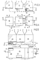
- 3 and 4 show the arrangement of the heating devices in multi-pressure condensers of a separate design for transverse installation.
- Low, medium and high pressure parts are designated by 10 or 11 and 12, the cooling water inlet connection and the cooling water outlet connection by 13 or 14 and the cooling water connecting lines between low and medium pressure part or between the latter and high pressure part by 15 and 16.
- the supercooled condensate is drawn off from the low and medium pressure parts 10 and 11 via condensate drain lines 17 and 18 into the high pressure part 12, where it passes through two heating devices 19 and 20, where it is practically heated to the saturation temperature , gets into the condensate collection container, from where it is drawn off through the condensate outlet connection 21 as boiler feed water.
- the structure of the heating devices is explained in detail below with reference to FIGS. 7 to 11.
- the level triangles in the condenser parts indicate the condensate water level.
- the air suction line is designated 22.
- the cooling water supply via the cooling water inlet connector 26, the two cooling water connecting lines 28 and 29 and the cooling water outlet connector 27 is analogous to that in the separate design according to FIGS. 3 and 4.
- the condensate pump 30 conveys the condensate into the feed water preheater.
- the first is arranged under the low-pressure part 23 and the latter under the medium-pressure part 24.
- the two heating devices 33 and 34 are housed here under the low pressure part 35.
- the two heating devices 33 and 34 are divided by dividing walls 38 and 39, which are arranged at right angles to the longitudinal axis of the condenser, into a respective heating chamber 40, 41 or 42, 43 for the heating of the low-pressure and medium-pressure condensate, which takes place separately from one another.
- the low pressure condensate is warmed up in the chambers 40 and 42, the medium pressure condensate in the chambers 41 and 43.
- the low-pressure condensate flows through slit-shaped condensate drain openings 44 and 45 directly adjacent to the wall of the condensate jacket into narrow, vertical drain channels 46 and 47, see FIG. 9, down to the bottom of the condenser, where it also leads into narrow, vertically upwards Ascending channels 48 and 49, also shown in FIG. 9, are deflected upwards and at the upper end thereof flows over to the uppermost of a row of perforated drip plates arranged one above the other.
- the above-mentioned elements of the heating device namely those on the right-hand side in FIG.
- FIG. 11 The top draining plate, designated 50, is unperforated at its right end 51 and covers one there Air collecting duct 52, from which the air collecting there is sucked off through an air suction line 53.
- the drip plate 50 and also all the drip plates 55 located below have a rim 56 at their free end, which prevents the condensate from flowing undesirably over the free edges of the drip plates, so that it has to drip down through their holes and from that through the arrows 57 symbolically represented upward flow of the high-pressure steam is heated to the saturation temperature.
- a few tubes of the condenser tube bundle 58 are shown above the heating device.
- the partitions 38 and 39 shown in FIG. 8 separate the warming-up chambers 40 and 42 for the low-pressure condensate from the two warming-up chambers 41 and 43 for the medium-pressure condensate.
- drain channels 62 and 63 located below are extend not only over the length of the discharge openings 59, 60, but also up to the dividing walls 38 and 39, from where the medium-pressure condensate in the two warming-up chambers 41 and 43 takes the same route as described above, the low-pressure condensate in the warming-up chambers 40 and 42 and flows into the condensate collection container 64 at the saturation temperature.
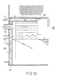
- a heating device 65 for a multi-pressure condenser of a separate type according to FIGS. 3 and 4 is shown in FIG. 10.
- Two such devices are provided in FIG. 4 in the high-pressure part of the condenser, one of which, 19, the low-pressure condensate and the second, 20, the medium pressure condensate warms up.
- the supercooled condensate enters the ascending channel 67 through a condensate drain line 66, which corresponds to one of the condensate drain lines 17 and 18 in FIGS. 3 and 4, flows over at its upper end into the highest draining plate 68, from where it is then as described with reference to FIG. 10, drips down through the draining plates underneath and is warmed up by the high-pressure steam.
- Air is sucked out of the air collecting duct 69 via an air suction line 70 and air is sucked out of the space above the highest draining plate 68 via a second air suction line 71.
Landscapes
- Engineering & Computer Science (AREA)
- Mechanical Engineering (AREA)
- General Engineering & Computer Science (AREA)
- Engine Equipment That Uses Special Cycles (AREA)
- Heat-Exchange Devices With Radiators And Conduit Assemblies (AREA)
- Control Of Turbines (AREA)
Claims (4)
Applications Claiming Priority (2)
| Application Number | Priority Date | Filing Date | Title |
|---|---|---|---|
| CH3163/83 | 1983-06-09 | ||
| CH316383 | 1983-06-09 |
Publications (2)
| Publication Number | Publication Date |
|---|---|
| EP0128346A1 EP0128346A1 (fr) | 1984-12-19 |
| EP0128346B1 true EP0128346B1 (fr) | 1986-09-10 |
Family
ID=4249980
Family Applications (1)
| Application Number | Title | Priority Date | Filing Date |
|---|---|---|---|
| EP84105115A Expired EP0128346B1 (fr) | 1983-06-09 | 1984-05-07 | Condenseur à plusieurs corps pour turbines à vapeur avec systèmes de réchauffement pour supprimer le sous-refroidissement du condensat |
Country Status (10)
| Country | Link |
|---|---|
| US (1) | US4598767A (fr) |
| EP (1) | EP0128346B1 (fr) |
| JP (1) | JPS6014096A (fr) |
| AU (1) | AU569890B2 (fr) |
| CA (1) | CA1225528A (fr) |
| DE (1) | DE3460673D1 (fr) |
| ES (1) | ES533219A0 (fr) |
| PL (1) | PL144509B1 (fr) |
| PT (1) | PT78707B (fr) |
| ZA (1) | ZA844196B (fr) |
Families Citing this family (14)
| Publication number | Priority date | Publication date | Assignee | Title |
|---|---|---|---|---|
| BG44654A1 (fr) * | 1985-11-10 | 1989-01-16 | Mikhail V Mikhajjlov | |
| JP3161072B2 (ja) * | 1992-09-10 | 2001-04-25 | 株式会社日立製作所 | 復水器とその運転方法、並びに復水系統とその運転方法 |
| IL153073A0 (en) | 2000-05-26 | 2003-06-24 | York Refrigeration Aps | Condenser with integrated deaerator |
| JP3706571B2 (ja) * | 2001-11-13 | 2005-10-12 | 三菱重工業株式会社 | 多段圧復水器 |
| BE1015880A3 (nl) | 2004-02-03 | 2005-10-04 | Atlas Copco Airpower Nv | Warmtewisselaar. |
| JP2008256279A (ja) * | 2007-04-05 | 2008-10-23 | Toshiba Corp | 復水設備 |
| WO2009075300A1 (fr) | 2007-12-10 | 2009-06-18 | Kabushiki Kaisha Toshiba | Condenseur de vapeur |
| US8220266B2 (en) * | 2009-03-12 | 2012-07-17 | General Electric Company | Condenser for power plant |
| JP5300618B2 (ja) * | 2009-06-24 | 2013-09-25 | 株式会社東芝 | 多段圧復水器 |
| CN101936669B (zh) * | 2010-09-02 | 2012-09-05 | 洛阳隆华传热科技股份有限公司 | 一种混联式复合凝汽方法及凝汽器 |
| JP5721471B2 (ja) | 2011-02-28 | 2015-05-20 | 三菱日立パワーシステムズ株式会社 | 多段圧復水器およびこれを備えた蒸気タービンプラント |
| US9488416B2 (en) | 2011-11-28 | 2016-11-08 | Mitsubishi Hitachi Power Systems, Ltd. | Multistage pressure condenser and steam turbine plant having the same |
| JP5936562B2 (ja) * | 2013-02-13 | 2016-06-22 | 三菱日立パワーシステムズ株式会社 | 復水器、これを備えている多段圧復水器、復水器に用いる再熱モジュール |
| JP6578247B2 (ja) * | 2016-06-13 | 2019-09-18 | 日立Geニュークリア・エナジー株式会社 | 複圧式復水器 |
Family Cites Families (7)
| Publication number | Priority date | Publication date | Assignee | Title |
|---|---|---|---|---|
| US2542873A (en) * | 1948-06-18 | 1951-02-20 | Ingersoll Rand Co | Multistage deaerating and reheating hot well for steam condensers |
| US3194021A (en) * | 1964-07-14 | 1965-07-13 | Westinghouse Electric Corp | Vapor condensing apparatus |
| US3698476A (en) * | 1970-12-31 | 1972-10-17 | Worthington Corp | Counter flow-dual pressure vent section deaerating surface condenser |
| JPS5223009B2 (fr) * | 1972-03-10 | 1977-06-21 | ||
| DE2737539A1 (de) * | 1977-08-19 | 1979-03-01 | Steag Ag | Verfahren zur verbesserung des waermeverbrauchs bei in reihe geschalteten kondensatoren mehrflutiger dampfturbinen und anordnung zur durchfuehrung des verfahrens |
| FR2426878A1 (fr) * | 1978-05-25 | 1979-12-21 | Alsthom Atlantique | Condenseur a plusieurs corps |
| JPS592836B2 (ja) * | 1979-02-23 | 1984-01-20 | 富士電機株式会社 | 直接接触式多段圧復水装置 |
-
1984
- 1984-05-07 DE DE8484105115T patent/DE3460673D1/de not_active Expired
- 1984-05-07 EP EP84105115A patent/EP0128346B1/fr not_active Expired
- 1984-05-22 US US06/613,021 patent/US4598767A/en not_active Expired - Lifetime
- 1984-05-31 CA CA000455571A patent/CA1225528A/fr not_active Expired
- 1984-06-05 ZA ZA844196A patent/ZA844196B/xx unknown
- 1984-06-07 PL PL1984248096A patent/PL144509B1/pl unknown
- 1984-06-07 PT PT78707A patent/PT78707B/pt unknown
- 1984-06-07 JP JP59115653A patent/JPS6014096A/ja active Pending
- 1984-06-07 ES ES533219A patent/ES533219A0/es active Granted
- 1984-06-08 AU AU29212/84A patent/AU569890B2/en not_active Ceased
Also Published As
| Publication number | Publication date |
|---|---|
| PT78707B (de) | 1986-07-11 |
| PT78707A (pt) | 1985-01-01 |
| AU2921284A (en) | 1984-12-13 |
| PL144509B1 (en) | 1988-06-30 |
| ES8505023A1 (es) | 1985-05-01 |
| ZA844196B (en) | 1985-05-29 |
| US4598767A (en) | 1986-07-08 |
| PL248096A1 (en) | 1985-02-13 |
| AU569890B2 (en) | 1988-02-25 |
| DE3460673D1 (en) | 1986-10-16 |
| CA1225528A (fr) | 1987-08-18 |
| EP0128346A1 (fr) | 1984-12-19 |
| JPS6014096A (ja) | 1985-01-24 |
| ES533219A0 (es) | 1985-05-01 |
Similar Documents
| Publication | Publication Date | Title |
|---|---|---|
| EP0128346B1 (fr) | Condenseur à plusieurs corps pour turbines à vapeur avec systèmes de réchauffement pour supprimer le sous-refroidissement du condensat | |
| EP0384200B1 (fr) | Condenseur à vapeur | |
| DE2754330A1 (de) | Vorrichtung zur kondensierung von wasserdampf oder anderen daempfen | |
| DE2602679A1 (de) | Verfahren zur herstellung eines luftgekuehlten, atmosphaerischen waermeaustauschers | |
| CH697746A2 (de) | Kombikraftwerk mit einer Vorrichtung für die Druckzufuhr an eine Sprühnebel-Einlasstemperaturreduktion von Gasturbinen sowie Verfahren zu dessen Betrieb. | |
| DE4340745C2 (de) | Verfahren und Vorrichtung zur Gewinnung von Brauchwasser aus verunreinigten Wässern | |
| DE2435429A1 (de) | Dampferzeuger | |
| DE1805652C3 (de) | Verfahren zur Gewinnung von Frischwasser aus einer wäßrigen Salzlösung sowie Vorrichtung zur Durchführung des Verfahrens | |
| DE2133807B2 (de) | Mehrstufiger Sprühfilmverdampfer zur Gewinnung von Brauchwasser aus Rohwasser | |
| EP0939288A1 (fr) | Système de condensation | |
| DE2949975A1 (de) | Dampferzeugeranordnung fuer kernkraftwerke | |
| DE69933202T2 (de) | Fallfilm-Verdampfer als Kondensationsverdampfer | |
| EP0325758B1 (fr) | Condenseur de vapeur | |
| DE1767207A1 (de) | Destillationsanlage | |
| DE3834716A1 (de) | Verfahren und vorrichtung zum aufkonzentrieren von loesungen | |
| EP0619466B1 (fr) | Condenseur de vapeur | |
| DE19642100B4 (de) | Dampfkondensator | |
| DE2223081A1 (de) | Mehrstufenverdampfungsverfahren und vorrichtung zur durchfuehrung des verfahrens.4 | |
| DE60006321T2 (de) | Verdampferkondensor mit hartgelöteten Platten und deren Verwendung in einer Luftdestillationsvorrichtung | |
| DE102010043729A1 (de) | Dampf- und Kondensatsystem für die Trockenpartie einer Faserbahnmaschine | |
| DE60103471T2 (de) | Wasserverteilerrohr | |
| DE2717505A1 (de) | Zweistufiger verdampfer | |
| DE1517385A1 (de) | Vorrichtung zum Verdampfen von Seewasser | |
| DE1027698B (de) | Luftgekuehlter Kondensator fuer ortsfeste Dampfkraftanlagen | |
| EP1576331A1 (fr) | Systeme de desaeration/degazage pour condensateurs de centrale electrique |
Legal Events
| Date | Code | Title | Description |
|---|---|---|---|
| PUAI | Public reference made under article 153(3) epc to a published international application that has entered the european phase |
Free format text: ORIGINAL CODE: 0009012 |
|
| AK | Designated contracting states |
Designated state(s): BE CH DE FR LI NL SE |
|
| 17P | Request for examination filed |
Effective date: 19841109 |
|
| GRAA | (expected) grant |
Free format text: ORIGINAL CODE: 0009210 |
|
| AK | Designated contracting states |
Kind code of ref document: B1 Designated state(s): BE CH DE FR LI NL SE |
|
| REF | Corresponds to: |
Ref document number: 3460673 Country of ref document: DE Date of ref document: 19861016 |
|
| ET | Fr: translation filed | ||
| PGFP | Annual fee paid to national office [announced via postgrant information from national office to epo] |
Ref country code: NL Payment date: 19870531 Year of fee payment: 4 |
|
| PLBE | No opposition filed within time limit |
Free format text: ORIGINAL CODE: 0009261 |
|
| STAA | Information on the status of an ep patent application or granted ep patent |
Free format text: STATUS: NO OPPOSITION FILED WITHIN TIME LIMIT |
|
| 26N | No opposition filed | ||
| PG25 | Lapsed in a contracting state [announced via postgrant information from national office to epo] |
Ref country code: NL Effective date: 19881201 |
|
| NLV4 | Nl: lapsed or anulled due to non-payment of the annual fee | ||
| PGFP | Annual fee paid to national office [announced via postgrant information from national office to epo] |
Ref country code: SE Payment date: 19890425 Year of fee payment: 6 |
|
| PGFP | Annual fee paid to national office [announced via postgrant information from national office to epo] |
Ref country code: CH Payment date: 19890823 Year of fee payment: 6 |
|
| PG25 | Lapsed in a contracting state [announced via postgrant information from national office to epo] |
Ref country code: SE Effective date: 19900508 |
|
| PG25 | Lapsed in a contracting state [announced via postgrant information from national office to epo] |
Ref country code: LI Effective date: 19900531 Ref country code: CH Effective date: 19900531 |
|
| REG | Reference to a national code |
Ref country code: CH Ref legal event code: PL |
|
| EUG | Se: european patent has lapsed |
Ref document number: 84105115.4 Effective date: 19910115 |
|
| PGFP | Annual fee paid to national office [announced via postgrant information from national office to epo] |
Ref country code: DE Payment date: 20020511 Year of fee payment: 19 |
|
| PGFP | Annual fee paid to national office [announced via postgrant information from national office to epo] |
Ref country code: FR Payment date: 20020513 Year of fee payment: 19 |
|
| PGFP | Annual fee paid to national office [announced via postgrant information from national office to epo] |
Ref country code: BE Payment date: 20020527 Year of fee payment: 19 |
|
| BECA | Be: change of holder's address |
Free format text: 20020424 *ALSTOM:25, AVENUE KLEBER, F-75116 PARIS |
|
| BECH | Be: change of holder |
Free format text: 20020424 *ALSTOM |
|
| BECN | Be: change of holder's name |
Effective date: 20020424 |
|
| PG25 | Lapsed in a contracting state [announced via postgrant information from national office to epo] |
Ref country code: BE Free format text: LAPSE BECAUSE OF NON-PAYMENT OF DUE FEES Effective date: 20030531 |
|
| BERE | Be: lapsed |
Owner name: *ALSTOM Effective date: 20030531 |
|
| PG25 | Lapsed in a contracting state [announced via postgrant information from national office to epo] |
Ref country code: DE Free format text: LAPSE BECAUSE OF NON-PAYMENT OF DUE FEES Effective date: 20031202 |
|
| PG25 | Lapsed in a contracting state [announced via postgrant information from national office to epo] |
Ref country code: FR Free format text: LAPSE BECAUSE OF NON-PAYMENT OF DUE FEES Effective date: 20040130 |
|
| REG | Reference to a national code |
Ref country code: FR Ref legal event code: ST |