EP0128346A1 - Mehrdruckkondensator für Dampfturbinen mit Aufwärmungseinrichtungen zur Unterdrückung der Unterkühlung des Kondensators - Google Patents
Mehrdruckkondensator für Dampfturbinen mit Aufwärmungseinrichtungen zur Unterdrückung der Unterkühlung des Kondensators Download PDFInfo
- Publication number
- EP0128346A1 EP0128346A1 EP84105115A EP84105115A EP0128346A1 EP 0128346 A1 EP0128346 A1 EP 0128346A1 EP 84105115 A EP84105115 A EP 84105115A EP 84105115 A EP84105115 A EP 84105115A EP 0128346 A1 EP0128346 A1 EP 0128346A1
- Authority
- EP
- European Patent Office
- Prior art keywords
- pressure
- condensate
- low
- medium
- condenser
- Prior art date
- Legal status (The legal status is an assumption and is not a legal conclusion. Google has not performed a legal analysis and makes no representation as to the accuracy of the status listed.)
- Granted
Links
- 238000001816 cooling Methods 0.000 title description 5
- 230000001629 suppression Effects 0.000 title description 2
- 238000003303 reheating Methods 0.000 title 1
- 238000010438 heat treatment Methods 0.000 claims abstract description 21
- 238000001704 evaporation Methods 0.000 claims abstract description 8
- 230000008020 evaporation Effects 0.000 claims abstract description 7
- 230000001174 ascending effect Effects 0.000 claims abstract description 3
- 238000004781 supercooling Methods 0.000 claims description 3
- 239000000498 cooling water Substances 0.000 description 6
- 238000000034 method Methods 0.000 description 6
- XLYOFNOQVPJJNP-UHFFFAOYSA-N water Substances O XLYOFNOQVPJJNP-UHFFFAOYSA-N 0.000 description 6
- 238000009434 installation Methods 0.000 description 4
- 239000003990 capacitor Substances 0.000 description 3
- 230000002631 hypothermal effect Effects 0.000 description 2
- 238000005192 partition Methods 0.000 description 2
- 230000005587 bubbling Effects 0.000 description 1
- 230000003628 erosive effect Effects 0.000 description 1
- 239000000203 mixture Substances 0.000 description 1
- 230000000717 retained effect Effects 0.000 description 1
- 238000010792 warming Methods 0.000 description 1
- 239000002699 waste material Substances 0.000 description 1
Images


Classifications
-
- F—MECHANICAL ENGINEERING; LIGHTING; HEATING; WEAPONS; BLASTING
- F28—HEAT EXCHANGE IN GENERAL
- F28B—STEAM OR VAPOUR CONDENSERS
- F28B9/00—Auxiliary systems, arrangements, or devices
- F28B9/08—Auxiliary systems, arrangements, or devices for collecting and removing condensate
-
- F—MECHANICAL ENGINEERING; LIGHTING; HEATING; WEAPONS; BLASTING
- F28—HEAT EXCHANGE IN GENERAL
- F28B—STEAM OR VAPOUR CONDENSERS
- F28B1/00—Condensers in which the steam or vapour is separate from the cooling medium by walls, e.g. surface condenser
- F28B1/02—Condensers in which the steam or vapour is separate from the cooling medium by walls, e.g. surface condenser using water or other liquid as the cooling medium
-
- Y—GENERAL TAGGING OF NEW TECHNOLOGICAL DEVELOPMENTS; GENERAL TAGGING OF CROSS-SECTIONAL TECHNOLOGIES SPANNING OVER SEVERAL SECTIONS OF THE IPC; TECHNICAL SUBJECTS COVERED BY FORMER USPC CROSS-REFERENCE ART COLLECTIONS [XRACs] AND DIGESTS
- Y10—TECHNICAL SUBJECTS COVERED BY FORMER USPC
- Y10S—TECHNICAL SUBJECTS COVERED BY FORMER USPC CROSS-REFERENCE ART COLLECTIONS [XRACs] AND DIGESTS
- Y10S165/00—Heat exchange
- Y10S165/184—Indirect-contact condenser
- Y10S165/192—Indirect-contact condenser including means to heat collected condensate
Definitions
- the present invention relates to a multi-pressure condenser for steam turbines with heating devices for suppressing supercooling of the condensate according to the preamble of patent claim 1.
- Another method for suppressing the condensate subcooling is that condensate originating from the low-pressure part in the medium-pressure part is dripped out of a distributor plate into waste steam derived from the high-pressure part.
- a structurally undesirable rather large drop height of the condensate drops is required.
- Subcooling of the condensate is highly penalized by the customer of the system due to the resulting higher operating costs, for example with a 1 million sFr / 1 ° C. Total suppression of hypothermia is therefore sought.
- the condensate from the medium-pressure and low-pressure section is supercooled by dropletization in the evaporation of the high-pressure section. This means that the overall height of the equipment required for this and thus the height of the capacitor jacket are significantly lower. are said to be in the above-mentioned types.
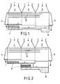
- FIG. 1 and 2 show the savings in overall height which can be achieved with a capacitor according to the invention, FIG. 1, compared to a capacitor of a known type according to FIG. 2.
- 1 denotes the low-pressure part
- 2 the medium-pressure part
- 3 the high-pressure part of a three-pressure condenser.
- the arrows in the steam inlet nozzle indicate the inflow directions of the exhaust steam from the low, medium and high pressure part of the turbine.
- the water inlet chamber 4 is shown on the left and the water outlet chamber 5 on the right.
- Some of the cooling pipe coils 6 are indicated within the condenser.
- the supercooled condensate is heated exclusively in the low-pressure part 1 in a heating device 7.
- the bottoms of the low-pressure part 1 and the medium-pressure part 2 are so like part of the bottom of the high-pressure part 3 are at the same level, only the rest of the bottom surface of the high-pressure part lowers and forms the condensate collector (Hotwell) 8 the condensate collector 8 larger.
- Low-, medium- and high-pressure part are designated by 10 and 11 and 12, the cooling water inlet nozzle and the cooling water outlet port 13 or 14 and thedewasserverbindun g sleitun g s between low and medium pressure part and between the latter and the high-pressure part with. 15 and 16
- the supercooled condensate is withdrawn from the low and medium pressure parts 10 and 11 via condensate drain lines 17 and 18, respectively, into the high pressure part 12, where it passes through two warm-up parts tion devices 19 and 20, wherein it is practically heated to the saturation temperature, gets into the condensate collection container, from where it is drawn off through the condensate outlet nozzle 21 as boiler feed water.
- the structure of the heating devices is explained in detail below with reference to FIGS. 7 to 11.
- the level triangles in the condenser parts indicate the condensate water level.
- the air suction line is designated 22.
- the cooling water supply via the cooling water inlet connector 26, the two cooling water connecting lines 28 and 29 and the cooling water outlet connector 27 is analogous to that in the separate design according to FIGS. 3 and 4.
- the condensate pump 30 conveys the condensate into the feed water preheater.
- the first is arranged under the low-pressure part 23 and the latter under the medium-pressure part 24.
- the two heating devices 33 and 34 are accommodated here under the low pressure part 35.
- the two heating devices 33 and 34 are each separated by a partition wall 38 and 39 arranged at right angles to the longitudinal axis of the condenser in a heating chamber 40, 41 and 42, 43, respectively taking place heating of the low-pressure and medium-pressure condensate divided.
- the low pressure condensate is warmed up in the chambers 40 and 42, the medium pressure condensate in the chambers 41 and 43.
- the low-pressure condensate flows through slit-shaped condensate drain openings 44 and 45 directly adjacent to the wall of the condensate jacket into narrow, vertical drain channels. 46 and 47, see Fig. 9, down to the bottom of the condenser, there is also narrow, vertically upward leading channels 48 and 49, also shown in Fig. 9, deflected upwards and flows at the upper end thereof on the top of a row of perforated drip plates one above the other at a distance.
- the aforementioned elements of the heating device namely those on the right side in FIG. 9, designated by 34, are schematic in FIG. 11. shown on a larger scale.
- the top draining plate, designated 50, is unperforated at its right end 51 and covers there an air collecting duct 52, from which the air collecting there is sucked off by an air suction line 53.
- the left boundary of the air collection duct 52, which seals it off from the dropping low-pressure condensate in the warming-up chamber 42, is formed by a vertical perforated plate 54 through which air and uncondensed steam reach the air collection duct 52, but the condensate drops are retained.
- the drip plate 50 and also all the drip plates 55 located below have a rim 56 at their free end, which prevents the condensate from flowing undesirably over the free edges of the drip plates, so that it has to drip down through their holes and from that through the arrows 57 represented symbolically Upward flow of the high pressure steam is heated to the saturation temperature.
- a few tubes of the condenser tube bundle 58 are shown above the heating device.
- the partitions 38 and 39 shown in FIG. 8 separate the warming-up chambers 40 and 42 for the low-pressure condensate from the two warming-up chambers 41 and 43 for the medium-pressure condensate.
- drain channels 62 and 63 located underneath are extend not only over the length of the discharge openings 59, 60, but also as far as the dividing walls 38 and 39, from where the medium-pressure condensate in the two warming-up chambers 41 and 43 takes the same path as the previously described low-pressure condensate in the warming-up chambers 40 and 42 and with the saturation temperature flows into the condensate collector 64.
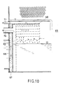
- a heating device 65 for a multi-pressure condenser of a separate type according to FIGS. 3 and 4 is shown in FIG. 10.
- Two such devices are provided in FIG. 4 in the high-pressure part of the condenser, one of which, 19, the low-pressure condensate and the second, 20, the medium pressure condensate warms up.
- the supercooled condensate passes through a condensate drain line 66, which in FIGS. 3 and 4 is one of the condensate drain lines lines 17 and 18 corresponds to the ascending channel 67, flows at its upper end into the highest draining plate 68, from where it then drips downward as described with reference to FIG. 10, through the underlying draining plates and is warmed up by the high pressure steam.
- Air is sucked out of the air collecting duct 69 via an air suction line 70 and air is sucked out of the space above the highest draining plate 68 via a second air suction line 71.
Landscapes
- Engineering & Computer Science (AREA)
- Mechanical Engineering (AREA)
- General Engineering & Computer Science (AREA)
- Engine Equipment That Uses Special Cycles (AREA)
- Heat-Exchange Devices With Radiators And Conduit Assemblies (AREA)
- Control Of Turbines (AREA)
Abstract
Description
- Die vorliegende Erfindung betrifft einen Mehrdruckkondensator für Dampfturbinen mit Aufwärmungseinrichtungen zur Unterdrückung der Unterkühlung des Kondensats nach dem Oberbegriff des Patentanspruchs 1.
- In Kondensatoren von Dampfturbinen soll dem Abdampf nur soviel Wärme entzogen werden, dass er sich in Kondensat verwandelt. Eine weitere Unterkühlung unter die Sättigungstemperatur des Abdampfes soll vermieden werden, da zum Ausgleich der damit verbundenen Wärmeverluste bei der Speisewasservorwärmung wieder Energie aufgewendet werden muss, was natürlich den Gesamtwirkungsgrad der Dampfturbinenanlage verschlechtert.
- Zur Unterdrückung dieser Unterkühlung ist es bekannt, bei Mehrdruckkondensatoren das unterkühlte Kondensat im Niederdruck- und Mitteldruckteil durch Abdampf aus dem Hochdruckteil des Kondensators aufzukochen. Mit angemessenem wirtschaftlichen Aufwand kann die Unterkühlung dabei aber nur teilweise verringert werden, weil nicht der gesamte Hochdruckabdampf kondensiert, sondern ein Teil desselben wegen der unvermeidlichen Leckage zwischen den Kondensatorteilen in den Mitteldruckteil und Niederdruckteil übergeht. Die angestrebte Verringerung des Wärmeverbrauchs oder Verbesserung des Kondensatorvakuums lässt sich auf diese Weise also nur unvollkommen erzielen. Ausserdem besteht dabei die Gefahr von Erosion an den Kühlrohrschlangen durch sprudelndes Kondensat, das gegen die Kühlrohre prallt.
- Ein weiteres Verfahren zur Unterdrückung der Kondensatunterkühlung besteht darin, dass aus dem Niederdruckteil stammendes Kondensat im Mitteldruckteil aus einer Verteilerplatten heraus in aus dem Hochdruckteil abgeleiteten Abdampf zertropft wird. Um die erwünschte Aufwärmung des kälteren Kondensats zu erreichen, ist eine baulich unerwünschte ziemlich grosse Fallhöhe der Kondensattropfen erforderlich.
- Derselbe Nachteil haftet einer Methode an, bei der aus dem Niederdruckteil und Mitteldruckteil abgezogenes Kondensat auf tieferliegende geneigte Platten im Hochdruckteil fliesst, von wo es über eine Höhe von ca. 1,5 m in den Sammelbehälter des Hochdruckteiles abfliesst und währenddessen durch den Hochdruckabdampf erwärmt wird.
- Bei einem weiteren bekannten Verfahren wird durch eine Pumpe unterkühltes Kondensat aus dem Niederdruckteil in den Hochdruckteil gefördert, dort zerstäubt und durch den Hochdruckabdampf erwärmt. Die störanfälligen rotierenden Teile der Pumpe bedeuten natürlich eine Einbusse an Verfügbarkeit, weshalb dieses Verfahren nicht empfohlen wird. Dazu kommt als weiterer Nachteil, dass die zum Antrieb der Pumpe erforderliche Energie den Gesamtwirkungsgrad der Turbinenanlage schmälert.
- Eine Unterkühlung des Kondensats wird vom Besteller der Anlage wegen der daraus resultierenden höheren Betriebskosten sehr hoch pönalisiert, beispielsweise mit einer 1 Mio sFr/1°C. Es wird daher eine totale Unterdrückung der Unterkühlung angestrebt.
- Mit der vorliegenden, im Patentanspruch 1 definierten Erfindung soll unter Vermeidung der Nachteile, welche die nach den obengenannten Verfahren betriebenen Bauarten aufweisen, eine Unterkühlung des Kondensats aus dem Mitteldruck- und Niederdruckteil durch Zertropfung im Abdampf des Hochdruckteiles erreicht werden. Das heisst, dass die Bauhöhe der dafür benötigten Einrichtungen und damit auch die Höhe des Kondensatormantels wesentlich niedriger sein. sollen als bei den erwähnten Bauarten.
- Die Erfindung wird im folgenden anhand von in den Zeichnungen dargestellten Ausführungsbeispielen näher beschrieben.
- In den Zeichnungen stellen dar:
- Fig. 1 schematisch einen Dreidruckkondensator gemäss der Erfindung,
- Fig. 2 schematisch einen Dreidruckkondensator bekannter Bauart, die
- Fig. 3 und 4 Auf- und Grundriss eines erfindungsgemässen Dreidruckkondensators in getrennter Bauart, in schematischer Schnittdarstellung, die
- Fig. 5 und 6 Auf- und Grundriss eines erfindungsgemässen, eine Einheit bildenden Dreidruckkondensators für Queraufstellung mit gemeinsamem Kondensatsammelbehälter, die
- Fig. 7, 8 und 9 Auf-, Grund- und Seitenriss eines Dreidruckkondensators gemäss der in den Fig. 5 und 6 gezeigten Bauform, für eine Aufstellung parallel zur Turbinenachse,
- Fig. 10 ein Schema der Aufwärmungseinrichtung für einen Mehrdruckkondensator getrennter Bauform nach den Fig. 3 und 4, und die
- Fig. 11 schematisch dargestellte Details aus der in den Fig. 7, 8 und 9 gezeigten Bauform.
- Aus den Fig. 1 und 2 geht die Ersparnis an Bauhöhe hervor, die mit einem erfindungsgemässen Kondensator, Fig. l, gegenüber einem Kondensator bekannter Bauart gemäss Fig. 2 zu erzielen ist.
- In den beiden Figuren bedeuten 1 den Niederdruckteil, 2 den Mitteldruckteil und 3 den Hochdruckteil eines Dreidruckkondensators. Die Pfeile in den Dampfeintrittsstutzen deuten die Einströmrichtungen des Abdampfes aus dem Nieder-, Mittel- und Hochdruckteil der Turbine an. Vom Kühlsystem sind links die Wassereintrittskammer 4 und rechts die Wasseraustrittskammer 5 gezeigt, innerhalb des Kondensators sind einige der Kühlrohrschlangen 6 angedeutet.
- Bei der erfindungsgemässen Ausführung nach Fig. 1 erfolgt die Aufwärmung des unterkühlten Kondensats ausschliesslich im Niederdruckteil 1 in einer Aufwärmungseinrichtung 7. Die Böden des Niederdruckteils 1 und des Mitteldruckteils 2 sowie ein Teil des Bodens des Hochdruckteils 3 liegen auf gleichem Niveau, lediglich der Rest der Bodenfläche des Hochdruckteils senkt sich ab und bildet den Kondensatsammelbehälter (Hotwell) 8. Die Bauhöhe eines solchen Kondensators ist gegenüber der Höhe des eigentlichen Kondensatorkastens inklusive Aufwärmungseinrichtung nur um die Tiefe des Kondensatsammelbehälters 8 grösser.
- Bei der Ausführung nach Fig. 2, bei der die Aufwärmung des unterkühlten Kondensats auf den Platten 9 in bekannter Weise so erfolgt, dass das unterkühlte Kondensat im-Nieder-. druckteil durch Abdampf aus dem Mitteldruckteil aufgewärmt und das sich im Mitteldruckteil ansammelnde Kondensatgemisch aus Nieder- und Hochdruckteil durch aus dem Hochdruckteil zuströmenden Abdampf weiter aufgewärmt wird. Wie eingangs erwähnt, benötigt dieses Verfahren für eine befriedigende Wirksamkeit eine ziemlich grosse Fallhöhe für das in den Platten 9 zu erwärmende Kondensat, woraus eine unerwünschte Vergrösserung der Bauhöhe des Kondenstroas um mindestens diese Fallhöhe resultiert.
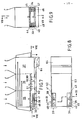
- Die Fig. 3 und 4 zeigen die Anordnung der Aufwärmungseinrichtungen in Mehrdruckkondensatoren getrennter Bauart für Queraufstellung. Nieder-, Mittel- und Hochdruckteil sind mit 10 bzw. 11 und 12 bezeichnet, der Kühlwassereintrittsstutzen und der Kühlwasseraustrittsstutzen mit 13 bzw. 14 und die Kühlwasserverbindungsleitungen zwischen Nieder- und Mitteldruckteil bzw. zwischen letzterem und Hochdruckteil mit 15 und 16.
- Bei dieser getrennten Bauart wird das unterkühlte Kondensat aus dem Nieder- und dem Mitteldruckteil 10 bzw. 11 über Kondensatabflussleitungen 17 bzw. 18 in den Hochdruckteil 12 abgezogen, wo es nach Passieren von zwei Aufwärmungseinrichtungen 19 und 20, wobei es praktisch auf die Sättigungstemperatur erwärmt wird, in den Kondensatsammelbehälter gelangt, von wo es durch den Kondensataustrittsstutzen 21 als Kesselspeisewasser abgezogen wird. Der Aufbau der Aufwärmungseinrichtungen wird im einzelnen unten anhand der Fig. 7 bis 11 erklärt. Die Niveaudreiecke in den Kondensatorteilen deuten die Kondensatwasserspiegel an. Die Luftabsaugleitung ist mit 22 bezeichnet.
- Ebenfalls für Queraufstellung vorgesehen ist der in den Fig. 5 und 6 schematisch dargestellte zusammengebaute Dreidruckkondensator, dessen drei Teile 23, 24 und 25 also eine Einheit bilden. Die Kühlwasserführung über den Kühlwassereintrittsstutzen 26, die beiden Kühlwasserverbindungsleitungen 28 und 29 und den Kühlwasseraustrittsstutzen 27 ist analog zu jener bei der getrennten Bauart nach den Fig. 3 und 4. Die Kondensatpumpe 30 fördert das Kondensat in den Speisewasservorwärmer.
- Von den zwei Aufwärmungseinrichtungen 31 und 32 ist die erste unter dem Niederdruckteil 23 und letztere unter dem Mitteldruckteil 24 angeordnet.
- Die Fig. 7, 8 und 9 zeigen schematisch im Dreiseitenriss einen zu einer Einheit zusammengebauten Dreidruckkondensator für einen Längseinbau parallel zur Turbinenachse. Die Bezugszahlen für die aus den vorher beschriebenen Ausführungen her bekannten Elemente sind, soweit für die Erklärung unwichtig, hier weggelassen. Die zwei Aufwärmungseinrichtungen 33 und 34 sind hier unter dem Niederdruckteil 35 untergebracht. Die beiden Aufwärmungseinrichtungen 33 und 34 sind durch rechtwinklig zur Längsachse des Kondensators angeordnete Trennwände 38 bzw. 39 in je eine Aufwärmkammer 40, 41 bzw. 42, 43 für die getrennt voneinander stattfindende Aufwärmung des Niederdruck- und des Mitteldruckkondensats unterteilt. Das Niederdruckkondensat wird in den Kammern 40 und 42, das Mitteldruckkondensat in den Kammern 41 und 43 aufgewärmt. Das Niederdruckkondensat fliesst durch unmittelbar an die Wandung des Kondensatmantels angrenzende, schlitzförmige Kondensatabflussöffnungen 44 bzw. 45 in schmale, senkrechte Abflusskanäle. 46 bzw. 47, siehe Fig. 9, nach unten zur Sohle des Kondensators, wird dort in ebenfalls schmale, senkrecht nach oben führende Aufsteigkanäle 48 und 49, ebenfalls aus Fig. 9 ersichtlich, nach oben umgelenkt und strömt am oberen Ende derselben auf die oberste einer Reihe von übereinander mit Abstand angeordneter, gelochter Abtropfplatt-en über. Die vorerwähnten Elemente der Aufwärmungseinrichtung, und zwar der in Fig. 9 auf der rechten Seite befindlichen, mit 34 bezeichneten, sind in Fig. 11 schematisch. in grösserem Massstab dargestellt. Die oberste, mit 50 bezeichnete Abtropfplatte ist an ihrem rechten Ende 51 ungelocht und überdeckt dort einen Luftsammelkanal 52, aus dem durch eine Luftabsaugleitung 53 die sich dort ansammelnde Luft abgesaugt wird. Die linke Begrenzung des Luftsammelkanals 52, die ihn gegen das zertropfende Niederdruckkondensat in der Aufwärmkammer 42 abschottet, wird von einer senkrechten Lochplatte 54 gebildet, durch die Luft und nichtkondensierter Dampf in den Luftsammelkanal 52 gelangt, die Kondensattropfen aber zurückgehalten werden.
- Die Abtropfplatte 50 und auch alle darunter befindlichen Abtropfplatten 55 weisen an ihrem freien Ende einen Bord 56 auf, der das unerwünschte Abfliessen des Kondensats über die freien Ränder der Abtropfplatten verhindert, so dass es durch deren Löcher nach unten tropfen muss und von der durch die Pfeile 57 symbolisch dargestellten Aufwärtsströmung des Hochdruckabdampfes auf die Sättigungstemperatur erwärmt wird. Oberhalb der Aufwärmungseinrichtung sind ein paar Rohre des Kondensatorrohrbündels 58 gezeigt.
- Die aus Fig. 8 ersichtlichen Trennwände 38 und 39 trennen die Aufwärmkammern 40 und 42 für das Niederdruckkondensat von den beiden Aufwärmkammern 41 und 43 für das Mitteldruckkondensat. Dieses strömt aus dem Mitteldruckteil 36 durch Kondensatabflussöffnungen 59 und 60, deren Länge dem Bereich entspricht, über den sich die Pfeile 61 erstrecken, siehe Fig. 7, nach unten in Abflusskanäle 62 und 63 von gleichem Querschnitt wie die Abflusskanäle 46 und 47 für das Niederdruck- bzw. Mitteldruckkondensat. Da die in Fig.7 eingetragene Schnittführung VIII-VIII, die dem Grundriss Fig. 8 entspricht, unterhalb der Kondensatabflussöffnungen 59, 60 liegt, sind diese Oeffnungen in Fig. 8 nicht zu sehen, wohl aber die darunter befindlichen Abflusskanäle 62 und 63, die sich nicht nur über die Länge der Abfluss- öffnungen 59, 60, sondern darüber hinaus bis zu den Trennwänden 38 und 39 erstrecken, von wo aus das Mitteldruckkondensat in den beiden Aufwärmkammern 41 und 43 den gleichen Weg nimmt wie vorgängig beschrieben das Niederdruckkondensat in den Aufwärmkammern 40 und 42 und mit der Sättigungstemperatur in den Kondensatsammelbehälter 64 abfliesst.
- Eine Aufwärmungseinrichtung 65 für einen Mehrdruckkondensator getrennter Bauart nach den Fig. 3 und 4 zeigt die Fig. 10. Zwei solcher Einrichtungen sind gemäss Fig. 4 im Hochdruckteil des Kondensators vorgesehen, von denen der eine, 19, das Niederdruckkondensat und der zweite, 20, das Mitteldruckkondensat aufwärmt. In Fig. 10 tritt das unterkühlte Kondensat durch eine Kondensatabflussleitung 66, der in den Fig. 3 und 4 eine der Kondensatabflussleitungen 17 und 18 entspricht, in den Aufsteigkanal 67 ein, fliesst an dessen oberem Ende in die höchstgelegene Abtropfplatte 68 über, von wo es dann wie anhand der Fig. 10 beschrieben, durch die darunter liegenden Abtropfplatten nach unten tropft und vom Hochdruckabdampf aufgewärmt wird. Ueber eine Luftabsaugeleitung 70 wird Luft dem Luftsammelkanal 69 und über eine zweite Luftabsaugeleitung 71 wird Luft aus dem Raum oberhalb der höchstgelegenen Abtropfplatte 68 abgesaugt.
Claims (4)
Applications Claiming Priority (2)
| Application Number | Priority Date | Filing Date | Title |
|---|---|---|---|
| CH316383 | 1983-06-09 | ||
| CH3163/83 | 1983-06-09 |
Publications (2)
| Publication Number | Publication Date |
|---|---|
| EP0128346A1 true EP0128346A1 (de) | 1984-12-19 |
| EP0128346B1 EP0128346B1 (de) | 1986-09-10 |
Family
ID=4249980
Family Applications (1)
| Application Number | Title | Priority Date | Filing Date |
|---|---|---|---|
| EP84105115A Expired EP0128346B1 (de) | 1983-06-09 | 1984-05-07 | Mehrdruckkondensator für Dampfturbinen mit Aufwärmungseinrichtungen zur Unterdrückung der Unterkühlung des Kondensators |
Country Status (10)
| Country | Link |
|---|---|
| US (1) | US4598767A (de) |
| EP (1) | EP0128346B1 (de) |
| JP (1) | JPS6014096A (de) |
| AU (1) | AU569890B2 (de) |
| CA (1) | CA1225528A (de) |
| DE (1) | DE3460673D1 (de) |
| ES (1) | ES533219A0 (de) |
| PL (1) | PL144509B1 (de) |
| PT (1) | PT78707B (de) |
| ZA (1) | ZA844196B (de) |
Cited By (3)
| Publication number | Priority date | Publication date | Assignee | Title |
|---|---|---|---|---|
| DE3637904A1 (de) * | 1985-11-10 | 1987-05-21 | Korabostroene K | Vakuumkondensator mit kondensatfalle fuer dampf |
| DE112008000892B4 (de) * | 2007-04-05 | 2010-11-11 | Kabushiki Kaisha Toshiba | Kondensationseinrichtung |
| EP2957847A4 (de) * | 2013-02-13 | 2016-11-23 | Mitsubishi Hitachi Power Sys | Kondensator, mehrstufiger hochdruckkondensator damit und in dem kondensator verwendetes wiedererwärmungsmodul |
Families Citing this family (12)
| Publication number | Priority date | Publication date | Assignee | Title |
|---|---|---|---|---|
| JP3161072B2 (ja) * | 1992-09-10 | 2001-04-25 | 株式会社日立製作所 | 復水器とその運転方法、並びに復水系統とその運転方法 |
| EP1290384B1 (de) | 2000-05-26 | 2006-04-05 | Teknologisk Institut | Integrierter entlüfter und kondensator |
| JP3706571B2 (ja) * | 2001-11-13 | 2005-10-12 | 三菱重工業株式会社 | 多段圧復水器 |
| BE1015880A3 (nl) * | 2004-02-03 | 2005-10-04 | Atlas Copco Airpower Nv | Warmtewisselaar. |
| JP5197602B2 (ja) | 2007-12-10 | 2013-05-15 | 株式会社東芝 | 復水器 |
| US8220266B2 (en) * | 2009-03-12 | 2012-07-17 | General Electric Company | Condenser for power plant |
| JP5300618B2 (ja) * | 2009-06-24 | 2013-09-25 | 株式会社東芝 | 多段圧復水器 |
| CN101936669B (zh) * | 2010-09-02 | 2012-09-05 | 洛阳隆华传热科技股份有限公司 | 一种混联式复合凝汽方法及凝汽器 |
| JP5721471B2 (ja) * | 2011-02-28 | 2015-05-20 | 三菱日立パワーシステムズ株式会社 | 多段圧復水器およびこれを備えた蒸気タービンプラント |
| US9488416B2 (en) | 2011-11-28 | 2016-11-08 | Mitsubishi Hitachi Power Systems, Ltd. | Multistage pressure condenser and steam turbine plant having the same |
| JP6578247B2 (ja) * | 2016-06-13 | 2019-09-18 | 日立Geニュークリア・エナジー株式会社 | 複圧式復水器 |
| CN115324672B (zh) * | 2022-09-20 | 2024-11-15 | 北京华晟智擎新能源有限公司 | 具有在线排气装置的低品位余热orc发电系统 |
Citations (4)
| Publication number | Priority date | Publication date | Assignee | Title |
|---|---|---|---|---|
| US2542873A (en) * | 1948-06-18 | 1951-02-20 | Ingersoll Rand Co | Multistage deaerating and reheating hot well for steam condensers |
| DE1426887A1 (de) * | 1964-07-14 | 1969-05-14 | Westinghouse Electric Corp | Waermekraftanlage mit Dampfturbine |
| US3817323A (en) * | 1972-03-10 | 1974-06-18 | Hitachi Ltd | Multistage condensers |
| FR2426878A1 (fr) * | 1978-05-25 | 1979-12-21 | Alsthom Atlantique | Condenseur a plusieurs corps |
Family Cites Families (3)
| Publication number | Priority date | Publication date | Assignee | Title |
|---|---|---|---|---|
| US3698476A (en) * | 1970-12-31 | 1972-10-17 | Worthington Corp | Counter flow-dual pressure vent section deaerating surface condenser |
| DE2737539A1 (de) * | 1977-08-19 | 1979-03-01 | Steag Ag | Verfahren zur verbesserung des waermeverbrauchs bei in reihe geschalteten kondensatoren mehrflutiger dampfturbinen und anordnung zur durchfuehrung des verfahrens |
| JPS592836B2 (ja) * | 1979-02-23 | 1984-01-20 | 富士電機株式会社 | 直接接触式多段圧復水装置 |
-
1984
- 1984-05-07 EP EP84105115A patent/EP0128346B1/de not_active Expired
- 1984-05-07 DE DE8484105115T patent/DE3460673D1/de not_active Expired
- 1984-05-22 US US06/613,021 patent/US4598767A/en not_active Expired - Lifetime
- 1984-05-31 CA CA000455571A patent/CA1225528A/en not_active Expired
- 1984-06-05 ZA ZA844196A patent/ZA844196B/xx unknown
- 1984-06-07 JP JP59115653A patent/JPS6014096A/ja active Pending
- 1984-06-07 ES ES533219A patent/ES533219A0/es active Granted
- 1984-06-07 PT PT78707A patent/PT78707B/de unknown
- 1984-06-07 PL PL1984248096A patent/PL144509B1/pl unknown
- 1984-06-08 AU AU29212/84A patent/AU569890B2/en not_active Ceased
Patent Citations (4)
| Publication number | Priority date | Publication date | Assignee | Title |
|---|---|---|---|---|
| US2542873A (en) * | 1948-06-18 | 1951-02-20 | Ingersoll Rand Co | Multistage deaerating and reheating hot well for steam condensers |
| DE1426887A1 (de) * | 1964-07-14 | 1969-05-14 | Westinghouse Electric Corp | Waermekraftanlage mit Dampfturbine |
| US3817323A (en) * | 1972-03-10 | 1974-06-18 | Hitachi Ltd | Multistage condensers |
| FR2426878A1 (fr) * | 1978-05-25 | 1979-12-21 | Alsthom Atlantique | Condenseur a plusieurs corps |
Cited By (3)
| Publication number | Priority date | Publication date | Assignee | Title |
|---|---|---|---|---|
| DE3637904A1 (de) * | 1985-11-10 | 1987-05-21 | Korabostroene K | Vakuumkondensator mit kondensatfalle fuer dampf |
| DE112008000892B4 (de) * | 2007-04-05 | 2010-11-11 | Kabushiki Kaisha Toshiba | Kondensationseinrichtung |
| EP2957847A4 (de) * | 2013-02-13 | 2016-11-23 | Mitsubishi Hitachi Power Sys | Kondensator, mehrstufiger hochdruckkondensator damit und in dem kondensator verwendetes wiedererwärmungsmodul |
Also Published As
| Publication number | Publication date |
|---|---|
| PL144509B1 (en) | 1988-06-30 |
| PT78707A (pt) | 1985-01-01 |
| ES8505023A1 (es) | 1985-05-01 |
| PL248096A1 (en) | 1985-02-13 |
| ZA844196B (en) | 1985-05-29 |
| CA1225528A (en) | 1987-08-18 |
| EP0128346B1 (de) | 1986-09-10 |
| AU2921284A (en) | 1984-12-13 |
| PT78707B (de) | 1986-07-11 |
| DE3460673D1 (en) | 1986-10-16 |
| ES533219A0 (es) | 1985-05-01 |
| US4598767A (en) | 1986-07-08 |
| JPS6014096A (ja) | 1985-01-24 |
| AU569890B2 (en) | 1988-02-25 |
Similar Documents
| Publication | Publication Date | Title |
|---|---|---|
| EP0128346B1 (de) | Mehrdruckkondensator für Dampfturbinen mit Aufwärmungseinrichtungen zur Unterdrückung der Unterkühlung des Kondensators | |
| DE69010830T2 (de) | Dampfpumpe mit Gegenstromaustauscher für Luft und Verbrennungsprodukte ohne Zwischenfluid. | |
| DE2754330A1 (de) | Vorrichtung zur kondensierung von wasserdampf oder anderen daempfen | |
| DE2602679A1 (de) | Verfahren zur herstellung eines luftgekuehlten, atmosphaerischen waermeaustauschers | |
| DE69715714T2 (de) | Vorrichtung und Verfahren zum Kondensieren von Dampf | |
| DE2333703A1 (de) | Mehrstufiger verdampfer | |
| US3830293A (en) | Tube and shell heat exchangers | |
| CH697746A2 (de) | Kombikraftwerk mit einer Vorrichtung für die Druckzufuhr an eine Sprühnebel-Einlasstemperaturreduktion von Gasturbinen sowie Verfahren zu dessen Betrieb. | |
| DE4340745C2 (de) | Verfahren und Vorrichtung zur Gewinnung von Brauchwasser aus verunreinigten Wässern | |
| DE2435429A1 (de) | Dampferzeuger | |
| DE2133807B2 (de) | Mehrstufiger Sprühfilmverdampfer zur Gewinnung von Brauchwasser aus Rohwasser | |
| EP0939288A1 (de) | Kondensationssystem | |
| DE69933202T2 (de) | Fallfilm-Verdampfer als Kondensationsverdampfer | |
| DE2949975A1 (de) | Dampferzeugeranordnung fuer kernkraftwerke | |
| DE3834716A1 (de) | Verfahren und vorrichtung zum aufkonzentrieren von loesungen | |
| DE1767207A1 (de) | Destillationsanlage | |
| DE2717505C2 (de) | Mehrstufiger Verdampfer | |
| DE1576848B2 (de) | Vorrichtung zum Abscheiden von Wasser aus Naßdampf und zum anschließenden Überhitzen des Dampfes | |
| EP3523587B1 (de) | Kühlaggregat | |
| EP0325758A1 (de) | Dampfkondensator | |
| DE19642100B4 (de) | Dampfkondensator | |
| DE2928392A1 (de) | Vorrichtung zur meerwasserentsalzung durch bruedenkompression | |
| DE1517597A1 (de) | Vielstufiger Entspannungsverdampfer | |
| DE2248566A1 (de) | Destilliergeraet | |
| DE3041754C2 (de) |
Legal Events
| Date | Code | Title | Description |
|---|---|---|---|
| PUAI | Public reference made under article 153(3) epc to a published international application that has entered the european phase |
Free format text: ORIGINAL CODE: 0009012 |
|
| AK | Designated contracting states |
Designated state(s): BE CH DE FR LI NL SE |
|
| 17P | Request for examination filed |
Effective date: 19841109 |
|
| GRAA | (expected) grant |
Free format text: ORIGINAL CODE: 0009210 |
|
| AK | Designated contracting states |
Kind code of ref document: B1 Designated state(s): BE CH DE FR LI NL SE |
|
| REF | Corresponds to: |
Ref document number: 3460673 Country of ref document: DE Date of ref document: 19861016 |
|
| ET | Fr: translation filed | ||
| PGFP | Annual fee paid to national office [announced via postgrant information from national office to epo] |
Ref country code: NL Payment date: 19870531 Year of fee payment: 4 |
|
| PLBE | No opposition filed within time limit |
Free format text: ORIGINAL CODE: 0009261 |
|
| STAA | Information on the status of an ep patent application or granted ep patent |
Free format text: STATUS: NO OPPOSITION FILED WITHIN TIME LIMIT |
|
| 26N | No opposition filed | ||
| PG25 | Lapsed in a contracting state [announced via postgrant information from national office to epo] |
Ref country code: NL Effective date: 19881201 |
|
| NLV4 | Nl: lapsed or anulled due to non-payment of the annual fee | ||
| PGFP | Annual fee paid to national office [announced via postgrant information from national office to epo] |
Ref country code: SE Payment date: 19890425 Year of fee payment: 6 |
|
| PGFP | Annual fee paid to national office [announced via postgrant information from national office to epo] |
Ref country code: CH Payment date: 19890823 Year of fee payment: 6 |
|
| PG25 | Lapsed in a contracting state [announced via postgrant information from national office to epo] |
Ref country code: SE Effective date: 19900508 |
|
| PG25 | Lapsed in a contracting state [announced via postgrant information from national office to epo] |
Ref country code: LI Effective date: 19900531 Ref country code: CH Effective date: 19900531 |
|
| REG | Reference to a national code |
Ref country code: CH Ref legal event code: PL |
|
| EUG | Se: european patent has lapsed |
Ref document number: 84105115.4 Effective date: 19910115 |
|
| PGFP | Annual fee paid to national office [announced via postgrant information from national office to epo] |
Ref country code: DE Payment date: 20020511 Year of fee payment: 19 |
|
| PGFP | Annual fee paid to national office [announced via postgrant information from national office to epo] |
Ref country code: FR Payment date: 20020513 Year of fee payment: 19 |
|
| PGFP | Annual fee paid to national office [announced via postgrant information from national office to epo] |
Ref country code: BE Payment date: 20020527 Year of fee payment: 19 |
|
| BECA | Be: change of holder's address |
Free format text: 20020424 *ALSTOM:25, AVENUE KLEBER, F-75116 PARIS |
|
| BECH | Be: change of holder |
Free format text: 20020424 *ALSTOM |
|
| BECN | Be: change of holder's name |
Effective date: 20020424 |
|
| PG25 | Lapsed in a contracting state [announced via postgrant information from national office to epo] |
Ref country code: BE Free format text: LAPSE BECAUSE OF NON-PAYMENT OF DUE FEES Effective date: 20030531 |
|
| BERE | Be: lapsed |
Owner name: *ALSTOM Effective date: 20030531 |
|
| PG25 | Lapsed in a contracting state [announced via postgrant information from national office to epo] |
Ref country code: DE Free format text: LAPSE BECAUSE OF NON-PAYMENT OF DUE FEES Effective date: 20031202 |
|
| PG25 | Lapsed in a contracting state [announced via postgrant information from national office to epo] |
Ref country code: FR Free format text: LAPSE BECAUSE OF NON-PAYMENT OF DUE FEES Effective date: 20040130 |
|
| REG | Reference to a national code |
Ref country code: FR Ref legal event code: ST |