EP0126165B2 - Gerät zum steuern der tonerkonzentration in einem entwickler - Google Patents
Gerät zum steuern der tonerkonzentration in einem entwickler Download PDFInfo
- Publication number
- EP0126165B2 EP0126165B2 EP83903586A EP83903586A EP0126165B2 EP 0126165 B2 EP0126165 B2 EP 0126165B2 EP 83903586 A EP83903586 A EP 83903586A EP 83903586 A EP83903586 A EP 83903586A EP 0126165 B2 EP0126165 B2 EP 0126165B2
- Authority
- EP
- European Patent Office
- Prior art keywords
- magnetic
- developer
- toner concentration
- toner
- detector
- Prior art date
- Legal status (The legal status is an assumption and is not a legal conclusion. Google has not performed a legal analysis and makes no representation as to the accuracy of the status listed.)
- Expired
Links
Images


Classifications
-
- G—PHYSICS
- G03—PHOTOGRAPHY; CINEMATOGRAPHY; ANALOGOUS TECHNIQUES USING WAVES OTHER THAN OPTICAL WAVES; ELECTROGRAPHY; HOLOGRAPHY
- G03G—ELECTROGRAPHY; ELECTROPHOTOGRAPHY; MAGNETOGRAPHY
- G03G15/00—Apparatus for electrographic processes using a charge pattern
- G03G15/06—Apparatus for electrographic processes using a charge pattern for developing
- G03G15/08—Apparatus for electrographic processes using a charge pattern for developing using a solid developer, e.g. powder developer
- G03G15/0822—Arrangements for preparing, mixing, supplying or dispensing developer
- G03G15/0848—Arrangements for testing or measuring developer properties or quality, e.g. charge, size, flowability
- G03G15/0849—Detection or control means for the developer concentration
- G03G15/0853—Detection or control means for the developer concentration the concentration being measured by magnetic means
Definitions
- This invention relates to an apparatus for controlling a toner, so that the toner can be replenished into a container depending on the output of a detector, which comprises the detector being disposed at a predetermined position in the container containing the toner, the detector being composed of a plurality of magnetic circuits having magnetic gaps, the coupling coefficient of one of the magnetic circuits being set at a value equivalent to the coupling coefficient exhibited when the toner is in a predetermined condition, while the coupling coefficient of another of the magnetic circuits is changeable in proportion to the toner condition, and the differential output of the two magnetic circuits is subjected to phase detection for comparing the coupling coefficient values of the two magnetic circuits.
- Developers used for electrophotographic copying apparatus, facsimile apparatus, printers, etc. include a two-component type developer in the form of a mixture of a magnetic carrier and a color toner.
- a two-component type developer in the form of a mixture of a magnetic carrier and a color toner.
- the color toner is consumed by attaching to the latent image although the magnetic carrier in the developer does not decrease, resulting in a decrease in the ratio of the color toner to the magnetic carrier in the developer (which ratio will be referred to hereinafter as a toner concentration).
- toner concentration control apparatus which detects the toner concentration of the developer to replenish the color toner in the developer.
- a planar electric coil has been disposed at a suitable position in the developer container surrounded by the stream of the developer, and, utilizing the fact that the coil inductance increases with the decrease of the toner concentration of the developer, the coil inductance value has been measured to detect the toner concentration.
- a developer level detector is disposed at a predetermined position in the developer container to monitor the quantity of the developer, and the shortage is filled up by the color toner so as to control the toner concentration.
- a back-coupling oscillation circuit using an electric coil acting as a detecting member is provided so as to detect the level of the developer on the basis of the oscillation level of this oscillation circuit.
- EP-A-112 928 An apparatus of the type mentioned in the beginning is disclosed in EP-A-112 928 which was published after the priority dates of this patent, which, however, is based on an earlier priority.
- This prior art apparatus comprises a magnetic toner level sensor for detecting the remaining volume of the toner in the toner container, i.e. as to whether the remaining volume of the toner is much or less in comparison with a predetermined value.
- this prior art relates to a detecting apparatus for detecting the presence or absence of the supply magnetic tone! without concerning the density of such magnetic toner.
- the present invention relates to an apparatus for detecting the intensity of toner, i.e. the change of mixture ratio of the. toner and carrier and controlling the intensity suitable for developing operation of an electronic copying machine.
- JP-A-56 54 573 teaches detecting patterns of magnetic particles on printed matters such as bank- notes.
- JP-A-52 145 042 teaches detecting toner concentration in a developer using a magnetic sensitive element.
- the present invention obviates various defects as pointed out above and has for its object to provide an apparatus for controlling the toner concentration of a developer, which operates stably with high accuracy without being affected by changes of external environmental conditions such as the temperature and humidity.
- the present invention provides an apparatus as in claim 1.
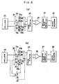
- FIG. 1 is a vertical sectional, side elevation view of a developing apparatus using an embodiment of the developer's toner concentration control apparatus according to the present invention.
- FIGs- 2, 3 and 4 are a view illustrating schematically the structure of a toner concentration detector used in the toner concentration control apparatus and illustrating the manner of operation of the detector respectively.
- FIG. 5 is a view illustrating schematically the structure of a toner concentration detector used in another embodiment of the developer's toner concentration control apparatus according to the present invention.
- 1 designates a side plate
- 2 designates a bottom plate made of a non-magnetic material
- the side plate 1 and bottom plate 2 constitute a developer container.
- 3 designates a magnet roll supported by the side plate 1
- 4 designates a sleeve of a non-magnetic material which is supported rotatably around the magnet roll 3 and is driven in the direction of the arrow A to rotate while holding a developer 5 attracted to its surface by the magnetic force of the magnet roll 3.
- 6 designates a separation plate for scraping off the developer from the surface of the sleeve 4
- 7 designates a stabilizer plate for stabilizing the level of the developer in the container
- 8 designates a stirrer rotating in the direction of the arrow B for making uniform the state of mixture of a magnetic carrier and a color toner in the developer
- 9 designates a cover having a toner replenishing opening 10.
- 11 designates a replenished toner hopper
- 12 designates a toner replenishing value
- 13 designates the color toner to be replenished.
- 14 and 15 designate detectors.
- the detector 14 is mounted on the bottom plate 2 at a portion opposite to the stabilizer plate 7 provided for stabilizing the level of the developer in the container.
- the detector 15 is fixed to the bottom plate 2 at a lower part of the container where the mixture ratio of the magnetic carrier and color toner in the developer is relatively stable without fluctuation.
- FIG. 1 (b) is a vertical sectional view of a developing apparatus using another embodiment of the developer's toner concentration control apparatus according to the present invention.
- 1 designates a side plate
- 2 designates a bottom plate made of a non-magnetic material
- the side plate 1 and bottom plate 2 constitute a developer container.
- 3 designates a magnet roll supported by the side plate 1
- 4 designates a sleeve of a non-magnetic material which is supported rotatably around the magnet roll 3 and is driven in the direction of the arrow A to rotate while holding a developer 5 attracted to its surface by the magnetic force of the magnet roll 3.
- a doctor blade 16 designates a doctor blade mounted on the side plate 1 to be spaced apart by a suitable distance value from the sleeve 4 so that a magnetic brush 17 of the developer has an appropriate size-
- the developer scraped off as an excess from the sleeve 4 by the doctor blade 16 passes along the upper surface of a conveying plate 18 in the directions of the arrows B and C to flow down onto a stirrer 8 to be circulated.
- 15 designates a detector which is mounted directly above the conveying plate 18 in a relation spaced apart by a suitable distance therefrom so as to detect the toner concentration of the devel- operflowing along the upper surface of the conveying plate 18.
- the stirrer 8 rotates in the direction of the arrow D and has the function of making uniform the state of mixture of a magnetic carrier and a color toner in the developer.
- 11 designates a replenished toner hopper
- 12 designates a toner replenishing value
- 13 designates the color toner to be replenished.
- the developing apparatus used in the present embodiment is of the so-called up-feed type in which the doctor blade is disposed above the magnet roll.
- the best position of mounting the detector in this type of developing apparatus is above the conveying plate 18 for the following reasons.
- the principal reason is that a portion of the developer forming the magnetic brush before the color toner is consumed in the developing step can be sampled so that the toner concentration can be stably detected.
- detectors 14 and 15 The structure and function of the detectors 14 and 15 will now be described with reference to FIG. 2, FIG. 3 and FIG. 4.
- FIGs. 2, 3 and 4 are a view illustrating schematically the structure of the detector in the toner concentration control apparatus of the present invention and illustrating the manner of operation of the detector respectively.
- the detector 14 or 15 in the present invention consists of U-shaped magnetic cores 21a and 21 b having magnetic gaps 22a and 22b which constitute two transformers 23a and 23b as shown in FIG. 2 (a).
- the transformers 23a and 23b have primary coils L i a, L lb and secondary coils L 2a , L 2b , wound therearound respectively.
- reference signal detecting coils L Ra and L Rb are wound.
- the primary coils L l , and L lb connected in series so that the flowing directions of magnetic flux are opposite to each other in the two magnetic circuits are connected to output terminals of an oscillator 24.
- the secondary coils L 2a and L 2b connected in series in opposite polarities so as to obtain their differential output and the reference signal detecting coils L Ra and L Rb connected in series in the same polarily, are connected to signal input terminals and reference signal input terminals respectively of a phase detector 25.
- the primary coils L 1a , L 1b , and the secondary coils L 2a , L 2b constitute a transformer of differential type, while the primary coils L 1a , L 1b and the reference signal detecting coils L Ra , L Rb a constitute a transformer of conventional type.
- the phase detector 25 is connected to apply its output to a potential comparator 26, and the output of the latter is connected to a replenishing valve driven circuit 27.
- the developer 5 is located in the magnetic gap 22a of the U-shaped core 21 a, while an adjusting screw (not shown) for adjusting the coupling coefficient of the transformer 23b is disposed in the magnetic gap 22b of the U-shaped core 21 b so as to adjust the coupling coefficient of the transformer to be equivalent to the value exhibited when the toner concentration lies within a predetermined range.
- the detector 15 shown in FIG. 1 (a) will be described with the rotation of the sleeve 4 of the developing apparatus in the direction of the arrow A, a magnetic brush of the developer 5 is formed on its surface to develop an electrostatic latent image. After development, the magnetic brush is separated by the separation plate 6 from the surface of the sleeve 4 to be scraped away toward the bottom of the container. The developer 5 thus scraped away is uniformly stirred by the stirrer 8 and is circulated to form the magnetic brush again.
- the stabilizer plate 7 stabilizes the level of the developer 5 in the container to be detected by the detector 14.
- the oscillation output from the oscillator 24 is applied to the primary coils L 1a and L 1b , the output signals corresponding to the coupling coefficients of the respective magnetic circuits are induced in the secondary coils L 2a and L 2b .
- the coupling coefficient of the magnetic circuit of the transformer 23a is equivalent to the coupling coefficient of the magnetic circuit of the transformer 23b previously set at this predetermined value, and the outputs of the two secondary coils L 2a and L 2b of opposite phase cancel each other to provide zero differential output.
- the phase detector 25 detects that differential output and generates a phase detector output corresponding to the specific phase.
- This output signal is compared in the potential comparator 26 with a reference voltage corresponding to the pre-set toner concentration, and its output actuates the replenishing valve driver circuit 27 to energize the toner replenishing valve 12 thereby replenishing the color toner 13.
- an adjusting transformer for fine adjustment may be additionally provided in the present invention so as to attain more delicate adjustment. That is, as shown in FIG. 2 (b), the primary coils L 1a and L lb are connected to the output terminals of the oscillator 24 through a primary coil L c1 of an adjusting transformer 29, and the secondary coils L 2a and L 2b connected in series in opposite polarities to obtain their differential output are connected to the signal input terminals of the phase detector 25 through a secondary coil L c2 of the adjusting transformer 29.
- the reference signal detecting coils L Ra and L Rb connected in series in the same polarity are connected to the signal input terminals and reference signal input terminals of the phase detector 25 respectively.
- the primary coils L 1a , L 1 b and the secondary coils L 2a , L 2b constitute a transformer of differential type
- the primary coils L 1a , L lb and the reference signal detecting coils L Ra and L Rb constitute a transformer of conventional type
- L c1 and L c2 constitute the adjusting transformer 29.
- the transformer 29 is shown to be of differential type in this example, it may be a transformer of conventional type.
- the phase detector 25 is connected to apply its output to the potential comparator 26, and the output of the latter is connected to the replenishing valve driver circuit 27.
- the output of this replenishing valve driver circuit 27 is applied to a driver mechanism 28 for driving the valve 12.
- the toner concentration is set by rotating the adjusting screw of a magnetic material mounted in the vicinity of the magnetic gap of the transformer 23b thereby changing the distance between it and the gap to provide a suitable coupling coefficient to the transformer 23b.
- the coupling coefficient changes greatly relative to the angular rotation of the screw, resulting in difficulty of accurate adjustment.
- the adjusting transformer 29 in the structure shown in FIG. 2 (b) has the function of compensating this defect, and, after the coupling coefficient value of the transformer 23b is roughly adjusted by the adjusting screw to a value close to the optimum value, the transformer 29 is manipulated for the accurate setting and fine adjustment.
- both of the primary side and the secondary side are connected in series with L 1a' L lb and L 2a , L 2b , and the whole circuit arrangement is as shown in FIG. 2 (b).
- a suitable AC output V adj is generated from the secondary side. Since the transformer is constructed to be of the differential type in this example, we can get not only the same phase AC output but also the opposite one to the reference phase.
- An AC signal having the adjusting transformer output V adj superposed on the differential output from L a and L b is applied to the phase detector.
- the toner concentration providing the same phase detector output is changed by the proportion corresponding to the superposition of V adj .
- the adjustment may be such that an AC voltage which is the same in amplitude as but opposite in phase to the differential output from the secondary coils at the illustrated concentration D + a is generated from the secondary side of the adjusting transformer.
- FIG. 4 schematically illustrates the secondary coil differential output, adjusting transformer output and phase detector input and output when the toner concentration setting is changed to D + a, D + 0 and D - a by the adjusting transformer while maintaining the adjusting screw added to the transformer 23b in the states of FIG. 3.
- FIG. 5 is a view schematically illustrating the structure of toner concentration detectors in another embodiment of the developer's toner concentration control apparatus.
- the present embodiment of the developer's toner concentration control apparatus is structurally different from the aforementioned embodiment of the toner concentration control apparatus in its toner concentration detectors only, and the remaining are substantially similar.
- 30 designates an H-shaped magnetic core, and a pair of magnetic circuits having magnetic gaps 31a and 31 b include a partly common magnetic path portion 32.
- the primary coil L 1 is wound around the partly common magnetic path portion 32 and is connected to the output terminals of the oscillator 24.
- the secondary coils L 2a , L 2b and the reference signal detecting coils L Ra , L Rb are wound symmetrically around arms 33a and 32b respectively of the H-shaped core 30.
- the secondary coils L 2a and L 2b connected in series in opposite polarities so as to obtain their differential output and the reference signal detecting coils L Ra and L Rb connected in series in the same a polarity, are connected to the signal input terminals and reference signal input terminals of the phase detector 25, as in the case of FIG. 2 showing the preceding embodiment.
- the phase detector 25 is connected to apply its output to the potential comparator 26, and the output of the latter is connected to the replenishing valve driver circuit 28.
- various characteristics such as the temperature characteristics of a plurality of magnetic circuits providing the detector part can be best compensated and matched when the individual magnetic circuits are formed of the same material and shaped and sized to be identical or symmetrical. Therefore, an arrangement as shown in FIG. 5 is very effective for stable detection of the toner concentration.
- the structure of the toner concentration detector in the present embodiment is as described above and its function and effect are similar to the function and effect of the toner concentration detector in the embodiment shown in FIG. 2, its explanation is omitted.
- a plurality of magnetic circuits having magnetic gaps are provided in a detector, and output signals of two magnetic circuits are compared to detect the toner concentration for replenishing a color toner, so that the detector is not substantially adversely affected by changes of the external environmental conditions including the temperature and humidity.
- a reference signal of a phase detector is derived as the output of the transformers in the detector in the aforementioned embodiments, the reference signal may be derived from the oscillator part, and, although an independent oscillator is used as the oscillator, an LC oscillator using its primary coil as an inductor may be employed.
- the primary coils Ha and L lb may be connected in parallel, and the function is similarly exhibited even when the directions of magnetic flux may be the same.
- phase detector 25 is used in the detector 14 or 15 in the embodiments, a phase comparator may also be used to decide, with high accuracy, an excess or a shortage of the toner concentration.
- the present invention can provide an apparatus for controlling, stably and with high accuracy, the toner concentration of a developer, which is not adversely affected by changes of the external environmental conditions including the temperature and moisture, and can be said to be an invention which is excellent in its practical effect.
Claims (7)
Applications Claiming Priority (6)
| Application Number | Priority Date | Filing Date | Title |
|---|---|---|---|
| JP207524/82 | 1982-11-29 | ||
| JP20752482A JPS5999462A (ja) | 1982-11-29 | 1982-11-29 | 現像剤のトナ−濃度制御装置 |
| JP20752582A JPS5999463A (ja) | 1982-11-29 | 1982-11-29 | 現像剤のトナ−濃度制御装置 |
| JP207525/82 | 1982-11-29 | ||
| JP95282/83 | 1983-05-30 | ||
| JP58095282A JPS59220764A (ja) | 1983-05-30 | 1983-05-30 | 現像剤のトナ−濃度制御装置 |
Publications (4)
| Publication Number | Publication Date |
|---|---|
| EP0126165A1 EP0126165A1 (de) | 1984-11-28 |
| EP0126165A4 EP0126165A4 (de) | 1986-11-25 |
| EP0126165B1 EP0126165B1 (de) | 1989-02-08 |
| EP0126165B2 true EP0126165B2 (de) | 1992-11-11 |
Family
ID=27307781
Family Applications (1)
| Application Number | Title | Priority Date | Filing Date |
|---|---|---|---|
| EP83903586A Expired EP0126165B2 (de) | 1982-11-29 | 1983-11-28 | Gerät zum steuern der tonerkonzentration in einem entwickler |
Country Status (5)
| Country | Link |
|---|---|
| US (1) | US4592645A (de) |
| EP (1) | EP0126165B2 (de) |
| DE (1) | DE3379182D1 (de) |
| DK (1) | DK319984D0 (de) |
| WO (1) | WO1984002202A1 (de) |
Families Citing this family (26)
| Publication number | Priority date | Publication date | Assignee | Title |
|---|---|---|---|---|
| EP0265942B1 (de) * | 1983-04-12 | 1992-08-26 | Mita Industrial Co. Ltd. | Elektrostatisches Kopiergerät |
| JPS61178656A (ja) * | 1985-02-04 | 1986-08-11 | Sharp Corp | 現像剤の濃度検出装置 |
| JPS61230175A (ja) * | 1985-04-03 | 1986-10-14 | Minolta Camera Co Ltd | 静電潜像現像装置 |
| JPS62229170A (ja) * | 1986-03-29 | 1987-10-07 | Toshiba Corp | 画像形成装置 |
| JPS6339249U (de) * | 1986-08-29 | 1988-03-14 | ||
| JPS63106679A (ja) * | 1986-10-23 | 1988-05-11 | Minolta Camera Co Ltd | 現像装置 |
| US5310425A (en) * | 1987-05-19 | 1994-05-10 | Tdk Corporation | Toner concentration detector for a two-component developer |
| JPH0633484Y2 (ja) * | 1987-05-19 | 1994-08-31 | ティーディーケイ株式会社 | トナ−濃度検出装置 |
| JPH01178990A (ja) * | 1987-12-29 | 1989-07-17 | Toshiba Corp | オートトナーセンサ |
| JP2528005Y2 (ja) * | 1988-01-06 | 1997-03-05 | シャープ株式会社 | 現像装置 |
| JPH01224787A (ja) * | 1988-03-04 | 1989-09-07 | Toshiba Corp | 画像形成装置 |
| JPH01261683A (ja) * | 1988-04-13 | 1989-10-18 | Minolta Camera Co Ltd | トナー濃度制御装置 |
| US4955317A (en) * | 1988-05-26 | 1990-09-11 | Minolta Camera Kabushiki Kaisha | Image forming apparatus having a plurality of developing units each containing two-component developer |
| US5040023A (en) * | 1988-09-14 | 1991-08-13 | Minolta Camera Kabushiki Kaisha | Method and apparatus for supplying toner to a developing device in an image forming apparatus |
| JP2574418B2 (ja) * | 1988-09-27 | 1997-01-22 | 三田工業株式会社 | 現像方法 |
| JPH02120771A (ja) * | 1988-10-31 | 1990-05-08 | Toshiba Corp | 画像形成装置およびその制御方法 |
| US4924263A (en) * | 1989-04-10 | 1990-05-08 | Xerox Corporation | Quality control for magnetic images |
| US5049938A (en) * | 1989-04-11 | 1991-09-17 | Minolta Camera Kabushiki Kaisha | Abnormality detecting system in an image forming apparatus |
| JP2625017B2 (ja) * | 1989-07-06 | 1997-06-25 | 富士通株式会社 | トナー濃度制御装置の調整方法 |
| JP3018395B2 (ja) * | 1990-05-15 | 2000-03-13 | ミノルタ株式会社 | 画像形成装置のトナー濃度制御装置 |
| US5081498A (en) * | 1991-01-10 | 1992-01-14 | Xerox Corporation | Humidity compensation in electrophotographic printing by measuring the dielectric characteristics of the development mixture |
| US5164775A (en) * | 1991-10-03 | 1992-11-17 | Eastman Kodak Company | Toner monitor system for development mixture control in electrostatographic apparatus |
| US5673106A (en) * | 1994-06-17 | 1997-09-30 | Texas Instruments Incorporated | Printing system with self-monitoring and adjustment |
| US5729787A (en) * | 1996-07-23 | 1998-03-17 | Eastman Kodak Company | Toner concentration monitor and method |
| JP3530751B2 (ja) | 1998-10-09 | 2004-05-24 | キヤノン株式会社 | プロセスカートリッジ及び電子写真画像形成装置 |
| JP3530752B2 (ja) * | 1998-10-09 | 2004-05-24 | キヤノン株式会社 | 電子写真画像形成装置、プロセスカートリッジ、現像装置、現像剤供給容器及び測定部品 |
Family Cites Families (11)
| Publication number | Priority date | Publication date | Assignee | Title |
|---|---|---|---|---|
| US3698926A (en) * | 1969-11-11 | 1972-10-17 | Katsuragawa Denki Kk | Method and apparatus for supplementing toner in electrophotographic machines |
| JPS5099552A (de) * | 1973-12-29 | 1975-08-07 | ||
| JPS52131729A (en) * | 1976-04-28 | 1977-11-04 | Ricoh Co Ltd | Toner concentration detection circuit |
| JPS5349437A (en) * | 1976-10-16 | 1978-05-04 | Hitachi Ltd | Toner density detector |
| JPS52145072A (en) * | 1977-02-28 | 1977-12-02 | Citizen Watch Co Ltd | Watch with battery life alarm display |
| US4270487A (en) * | 1977-10-27 | 1981-06-02 | Hitachi, Ltd. | Developer regulating device in developing apparatus |
| JPS55161261A (en) * | 1979-06-01 | 1980-12-15 | Katsuragawa Denki Kk | Toner replenishing method and its device |
| DD151814A1 (de) * | 1980-06-30 | 1981-11-04 | Guenter Schott | Messgeraet zur untersuchung des barkhausen-rauschens |
| JPS57111566A (en) * | 1980-12-29 | 1982-07-12 | Fujitsu Ltd | Detecting circuit for toner density |
| JPS57172245A (en) * | 1981-03-24 | 1982-10-23 | Copyer Co Ltd | Toner concentration controlling circuit of electronic copier |
| JPS5886451A (ja) * | 1981-11-18 | 1983-05-24 | Casio Comput Co Ltd | 現像剤の濃度検知装置 |
-
1983
- 1983-11-28 US US06/624,688 patent/US4592645A/en not_active Expired - Lifetime
- 1983-11-28 WO PCT/JP1983/000422 patent/WO1984002202A1/ja active IP Right Grant
- 1983-11-28 DE DE8383903586T patent/DE3379182D1/de not_active Expired
- 1983-11-28 EP EP83903586A patent/EP0126165B2/de not_active Expired
-
1984
- 1984-06-29 DK DK319984A patent/DK319984D0/da not_active Application Discontinuation
Also Published As
| Publication number | Publication date |
|---|---|
| WO1984002202A1 (en) | 1984-06-07 |
| EP0126165A4 (de) | 1986-11-25 |
| US4592645A (en) | 1986-06-03 |
| DK319984A (da) | 1984-06-29 |
| DE3379182D1 (en) | 1989-03-16 |
| DK319984D0 (da) | 1984-06-29 |
| EP0126165A1 (de) | 1984-11-28 |
| EP0126165B1 (de) | 1989-02-08 |
Similar Documents
| Publication | Publication Date | Title |
|---|---|---|
| EP0126165B2 (de) | Gerät zum steuern der tonerkonzentration in einem entwickler | |
| US4270487A (en) | Developer regulating device in developing apparatus | |
| JP2007256469A (ja) | トナー濃度制御装置及び画像形成装置 | |
| US4088092A (en) | Toner density sensing apparatus for electrostatic copying machine | |
| US4519696A (en) | Xerographic copying apparatus | |
| US4660505A (en) | Developing apparatus | |
| US4054230A (en) | Method of detecting a toner concentration | |
| US5212522A (en) | Basic developability control in single component development system | |
| JPH11223620A (ja) | トナー濃度検出装置及びトナー濃度検出装置の製造方法 | |
| JPS5953864A (ja) | 画像調整方法 | |
| JPH0656531B2 (ja) | 電子写真プロセスにおける現像装置 | |
| JP2004163602A (ja) | 透磁率検知装置 | |
| JPH01291274A (ja) | 電子写真装置の現像装置 | |
| JP6928893B2 (ja) | 画像形成装置、及び、粉体収容装置 | |
| JPH0375861B2 (de) | ||
| JPS5999462A (ja) | 現像剤のトナ−濃度制御装置 | |
| JPS6157972A (ja) | 現像剤の濃度制御装置 | |
| JPS59164576A (ja) | 現像装置 | |
| JPH0450880A (ja) | 電子写真装置の現像装置 | |
| JPS59232375A (ja) | 現像装置 | |
| JP2001092200A (ja) | 画像形成装置 | |
| JPH03261980A (ja) | 電子写真装置のトナー濃度制御装置 | |
| JPS5999463A (ja) | 現像剤のトナ−濃度制御装置 | |
| JPS59220764A (ja) | 現像剤のトナ−濃度制御装置 | |
| JPS62108271A (ja) | 現像剤の濃度制御装置 |
Legal Events
| Date | Code | Title | Description |
|---|---|---|---|
| PUAI | Public reference made under article 153(3) epc to a published international application that has entered the european phase |
Free format text: ORIGINAL CODE: 0009012 |
|
| 17P | Request for examination filed |
Effective date: 19840522 |
|
| AK | Designated contracting states |
Designated state(s): DE FR GB |
|
| RIN1 | Information on inventor provided before grant (corrected) |
Inventor name: TASHIRO, SADAJI Inventor name: SHIMOE, OSAMU Inventor name: KANAI, KENICHI |
|
| A4 | Supplementary search report drawn up and despatched |
Effective date: 19861125 |
|
| 17Q | First examination report despatched |
Effective date: 19871102 |
|
| GRAA | (expected) grant |
Free format text: ORIGINAL CODE: 0009210 |
|
| AK | Designated contracting states |
Kind code of ref document: B1 Designated state(s): DE FR GB |
|
| REF | Corresponds to: |
Ref document number: 3379182 Country of ref document: DE Date of ref document: 19890316 |
|
| ET | Fr: translation filed | ||
| PLBI | Opposition filed |
Free format text: ORIGINAL CODE: 0009260 |
|
| 26 | Opposition filed |
Opponent name: KONDO, MISAO Effective date: 19891107 |
|
| PUAH | Patent maintained in amended form |
Free format text: ORIGINAL CODE: 0009272 |
|
| STAA | Information on the status of an ep patent application or granted ep patent |
Free format text: STATUS: PATENT MAINTAINED AS AMENDED |
|
| 27A | Patent maintained in amended form |
Effective date: 19921111 |
|
| AK | Designated contracting states |
Kind code of ref document: B2 Designated state(s): DE FR GB |
|
| ET3 | Fr: translation filed ** decision concerning opposition | ||
| PGFP | Annual fee paid to national office [announced via postgrant information from national office to epo] |
Ref country code: FR Payment date: 20011113 Year of fee payment: 19 |
|
| PGFP | Annual fee paid to national office [announced via postgrant information from national office to epo] |
Ref country code: GB Payment date: 20011128 Year of fee payment: 19 |
|
| PGFP | Annual fee paid to national office [announced via postgrant information from national office to epo] |
Ref country code: DE Payment date: 20011210 Year of fee payment: 19 |
|
| REG | Reference to a national code |
Ref country code: GB Ref legal event code: IF02 |
|
| PG25 | Lapsed in a contracting state [announced via postgrant information from national office to epo] |
Ref country code: GB Free format text: LAPSE BECAUSE OF NON-PAYMENT OF DUE FEES Effective date: 20021128 |
|
| PG25 | Lapsed in a contracting state [announced via postgrant information from national office to epo] |
Ref country code: DE Free format text: LAPSE BECAUSE OF NON-PAYMENT OF DUE FEES Effective date: 20030603 |
|
| GBPC | Gb: european patent ceased through non-payment of renewal fee | ||
| PG25 | Lapsed in a contracting state [announced via postgrant information from national office to epo] |
Ref country code: FR Free format text: LAPSE BECAUSE OF NON-PAYMENT OF DUE FEES Effective date: 20030731 |
|
| REG | Reference to a national code |
Ref country code: FR Ref legal event code: ST |