EP0125377A2 - Kupplung mit Membranfeder-Reibteller, insbesondere für Kraftfahrzeuge - Google Patents
Kupplung mit Membranfeder-Reibteller, insbesondere für Kraftfahrzeuge Download PDFInfo
- Publication number
- EP0125377A2 EP0125377A2 EP84100726A EP84100726A EP0125377A2 EP 0125377 A2 EP0125377 A2 EP 0125377A2 EP 84100726 A EP84100726 A EP 84100726A EP 84100726 A EP84100726 A EP 84100726A EP 0125377 A2 EP0125377 A2 EP 0125377A2
- Authority
- EP
- European Patent Office
- Prior art keywords
- pressure plate
- clutch
- belts
- clutch housing
- diaphragm spring
- Prior art date
- Legal status (The legal status is an assumption and is not a legal conclusion. Google has not performed a legal analysis and makes no representation as to the accuracy of the status listed.)
- Granted
Links
Images
Classifications
-
- F—MECHANICAL ENGINEERING; LIGHTING; HEATING; WEAPONS; BLASTING
- F16—ENGINEERING ELEMENTS AND UNITS; GENERAL MEASURES FOR PRODUCING AND MAINTAINING EFFECTIVE FUNCTIONING OF MACHINES OR INSTALLATIONS; THERMAL INSULATION IN GENERAL
- F16D—COUPLINGS FOR TRANSMITTING ROTATION; CLUTCHES; BRAKES
- F16D13/00—Friction clutches
- F16D13/58—Details
- F16D13/70—Pressure members, e.g. pressure plates, for clutch-plates or lamellae; Guiding arrangements for pressure members
- F16D13/71—Pressure members, e.g. pressure plates, for clutch-plates or lamellae; Guiding arrangements for pressure members in which the clutching pressure is produced by springs only
-
- F—MECHANICAL ENGINEERING; LIGHTING; HEATING; WEAPONS; BLASTING
- F16—ENGINEERING ELEMENTS AND UNITS; GENERAL MEASURES FOR PRODUCING AND MAINTAINING EFFECTIVE FUNCTIONING OF MACHINES OR INSTALLATIONS; THERMAL INSULATION IN GENERAL
- F16D—COUPLINGS FOR TRANSMITTING ROTATION; CLUTCHES; BRAKES
- F16D13/00—Friction clutches
- F16D13/58—Details
- F16D13/70—Pressure members, e.g. pressure plates, for clutch-plates or lamellae; Guiding arrangements for pressure members
- F16D2013/706—Pressure members, e.g. pressure plates, for clutch-plates or lamellae; Guiding arrangements for pressure members the axially movable pressure plate is supported by leaf springs
Definitions
- the invention relates to a clutch with a friction plate, the axially movable pressure plate being pressed by means of a diaphragm spring over the friction plate onto the flywheel and the pressure plate being connected to the clutch housing via flexible bands.
- these flexible belts The primary purpose of these flexible belts is to transmit the torque emitted by the motor to the pressure plate and to guide the pressure plate centrally. In some cases, these belts also have the task of lifting the pressure plate off the friction plate when the clutch is disengaged; the straps are preloaded accordingly.
- the aim of the invention is to remedy the disadvantage mentioned without disadvantageous constructive solutions.
- the invention is based on the knowledge that a force can be generated by a new arrangement of the flexible bands, which is added to the spring force of the diaphragm spring while increasing its spring force and thereby increases the torque transmission capacity of the clutch, so that the sliding torque of the clutch despite wear of the friction linings is not reduced.
- the invention thus relates to a clutch with a diaphragm spring friction plate, in particular for motor vehicles, with flexible belts connecting the clutch housing and the pressure plate and dragging the pressure plate with the rotation of the clutch housing, the belts enclosing an angle of at least 5 ° greater than the pressure plate surface from the length between the inclusion points of the tape and from the Size of the permitted wear of the friction elements calculated angle value, and wherein the inclusion point of the belts located on the clutch housing is closer to the flywheel surface than their inclusion point located on the pressure plate.
- the bands are rotatably fastened both on the clutch housing and on the pressure plate in their own surface.
- the use of the invention has several advantages, because the invention allows a clutch with a higher torque to be built using the same diaphragm spring; the disengagement device is less stressed; the behavior of the coupling due to wear is compensated by the flexible belts.
- Another advantage can be that the tapes are not increasingly stressed with increasing wear.
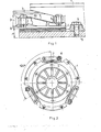
- Fig. 1 and 2 illustrated coupling consists in the known manner, of a coupling housing 1, a pressure plate 2, from an M embranfeder 3 and from a friction plate 6.
- the clutch housing 1 is fastened by means of screws 4 to a flywheel 5 of an internal combustion engine.
- the pressure plate 2 is connected to the clutch housing 1 by means of bands 7, which are arranged radially at a distance from the clutch axis and extend tangentially to it. In the illustrated case, three bands are arranged, but their number can be increased if necessary.
- the belts 7 are fastened to the clutch housing 1 and to the pressure plate 2 by means of their pivoting about bolts 8 which permit pivot axes running parallel to the coupling axis.
- the clutch rotates in the direction indicated by the arrow in Fig. 2; the clutch housing 1 takes the pressure plate 2 by means of the belts 7 by train.
- a collecting surface or support surface parallel to the pressure plate surface is formed, and on these collecting surfaces the belts 7 are on the underside of the band end fastened to the pressure plate 2 or on the flywheel 5 facing the flywheel 5 turned away from the top of their attached to the clutch housing 1 band end.
- the collecting surface formed on the pressure plate 2 is arranged at a greater axial distance from the surface of the flywheel 5 than the collecting surface on the clutch housing, the band 7 is double angled, one end of the band being angled towards the opposite side of the band surface than that the other band end and the band ends form an obtuse angle with the band surface, and its band section between its two clamping or inclusion points encloses an angle with the surface of the pressure plate 2.
- the inclusion point is to be understood as those points of the band 7 between which the deformation thereof is not limited by support. In this case, they are two Inclusion points the corner 9 of the collecting surface on the clutch housing 1 and the corner 10 of the collecting surface on the pressure plate 2.
- a proportionally weaker diaphragm spring can be used for the same clutch. In this case, the load on the lifting device becomes smaller.
- the torque transmission capacity of the clutch can be kept essentially at the same level over the entire life of the friction lining, and the characteristics of the force and the torque are much flatter.
- the constructive means required for this are simple and cheap and do not require any modifications worth mentioning in the usual design of the couplings with a diaphragm spring.
- a force in the band surface also acts on the bands. This arises from the fact that the dimensions of the coupling in the cold and in the warm state are not proportional to each other for the individual coupling parts.
- the pressure plate heats up more than the clutch housing, and its dimensions also change to a greater extent. Therefore, the two ends of the band are not evenly displaced in the radial direction. Therefore, the straps are curved or twisted in their own area if the straps are rigidly attached to the pressure plate or the coupling housing by means of bolts or screws. This strain is very disadvantageous. To avoid this disadvantage, it is therefore preferred to fasten the straps by means of bolts such that their pivoting about the bolt axis is permitted.
Landscapes
- Engineering & Computer Science (AREA)
- General Engineering & Computer Science (AREA)
- Mechanical Engineering (AREA)
- Mechanical Operated Clutches (AREA)
- Springs (AREA)
- Moving Of Heads (AREA)
- Pharmaceuticals Containing Other Organic And Inorganic Compounds (AREA)
- Acyclic And Carbocyclic Compounds In Medicinal Compositions (AREA)
- Medicines Containing Antibodies Or Antigens For Use As Internal Diagnostic Agents (AREA)
Abstract
Description
- Die Erfindung bezieht sich auf eine Kupplung mit Reibteller, wobei die axial bewegliche Druckplatte mittels einer Membranfeder über den Reibteller auf das Schwungrad gepreßt wird und die Druckplatte über flexible Bänder mit dem Kupplungsgehäuse verbunden ist.
- Diese flexiblen Bänder dienen in erster Reihe dazu, das vom Motor abgegebene Drehmoment auf die Druckplatte zu übertragen und die Druckplatte zentrisch zu führen. In einigen Fällen haben diese Bänder auch die Aufgabe, die Druckplatte beim Auskuppeln der Kupplung vom Reibteller abzuheben; hierbei sind die Bänder entsprechend vorgespannt.
- Die bisher bekannten Kupplungen mit flexiblen Bändern haben ohne Ausnahme den Nachteil, daß die Federkraft dieser flexiblen Bänder derjenigen der Membranfeder entgegenwirkt. Dadurch vermindert sich die die Momentübertragung sichernde ursprüngliche Federkraft stufenweise beim Ver- schleißen der Reibbeläge, und wenn der Verschleiß der Reibbeläge das zugelassene Maximum erreicht hat, ist das Gleitmoment der Kupplung am geringsten. Dieser Nachteil kommt in gesteigertem Maße zum Vorschein, wenn die flexiblen Bänder zum Abheben der Druckplatte beim Auskuppeln vorgespannt sind. Zur Beseitigung dieses Nachteiles sind die Ausführungsformen gemäß DD-A-139.153 und US-A-3,695, 404 bestimmt. Das Wesen beider Ausführungsformen besteht darin, die Federkonstante und dadurch auch die negative Wirkung der Federkraft der flexiblen Bänder durch Erhöhung der Länge der flexiblen Bänder zu vermindern. Diese Ausführungsformen haben den gemeinsamen Nachteil, daß die negative Wirkung nicht beseitigt ist, und gleichzeitig konstruktive Schwierigkeiten durch die Länge der Bänder vorliegen, was nur durch Kompromisse zu lösen war.
- Ziel der Erfindung ist es, den erwähnten Nachteil ohne nachteilige konstruktive Lösungen zu beheben. Die Erfindung basiert auf der Erkenntnis, daß durch eine neue Anordnung der flexiblen Bänder eine Kraft erzeugt werden kann, die sich mit der Federkraft der Membranfeder unter Erhöhung von deren Federkraft addiert und dadurch die Momentübertragungsfähigkeit der Kupplung erhöht, so daß sich das Gleitmoment der Kupplung trotz des Verschleißes der Reibbeläge nicht vermindert.
- Gegenstand der Erfindung ist somit eine Kupplung mit Membranfeder-Reibteller, insbesondere für Kraftfahrzeuge, mit das Kupplungsgehäuse und die Druckplatte verbindenden und die Druckplatte bei der Drehung des Kupplungsgehäuses mitschleppenden flexiblen Bändern, wobei die Bänder mit der Druckplattenfläche einen um mindestens 5° größeren Winkel einschließen als der aus der Länge zwischen den Einschließungspunkten des Bandes und aus der Größe des zugelassenen Verschleißes der Reibelemente berechnete Winkelwert, und wobei der am Kupplungsgehäuse befindliche Einschließungspunkt der Bänder näher an der Schwungradfläche liegt als ihr an der Druckplatte befindlicher Einschließungspunkt.
- Bei einer vorteilhaften.Ausführungsform der erfindungsgemäßen Kupplung mit Membranfeder-Reibteller sind die Bänder sowohl am Kupplungsgehäuse als auch an der Druckplatte in ihrer eigenen Fläche verdrehbar befestigt.
- Die Verwendung der Erfindung hat mehrere Vorteile, denn durch die Erfindung kann eine Kupplung mit größerem Moment bei Anwendung der gleichen Membranfeder gebaut werden; die Beanspruchung der Ausrückeinrichtung ist geringer; von den flexiblen Bändern wird das Verhalten der Kupplung aufgrund des Verschleißes ausgeglichen.
- Ein weiterer Vorteil kann darin bestehen, daß die Bänder mit zunehmendem Verschleiß nicht zunehmend beansprucht werden.
- Die Erfindung wird anhand eines Ausführungsbeispiels und der Zeichnungen näher erläutert. In der Zeichnung zeigt:
- Fig. 1. die Seitenansicht einer erfindungsgemäßen Kupplung,
- Fig. 2. die Draufsicht der erfindungsgemäßen Kupplung aus Fig..1
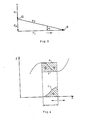
- Fig. 3. das Kräftedreieck der infolge der flexiblen Bänder auftretenden Kräfte und
- Fig. 4.. das Diagramm mit der Charakteristik der Kupplung und mit der Entwicklung der Abhebekraft.
- Die in Fig. 1. und 2. dargestellte Kupplung besteht in der bekannten Weise aus einem Kupplungsgehäuse 1, aus einer Druckplatte 2, aus einer Membranfeder 3 und aus einem Reibteller 6. Das Kupplungsgehäuse 1 ist mittels Schrauben 4 an einem Schwungrad 5 eines Verbrennungsmotors befestigt. Die Druckplatte 2 ist über radial im Abstand von der Kupplungsachse angeordnete, tangential zu dieser verlaufende Bänder 7 mit dem Kupplungsgehäuse 1 verbunden. Im dargestellten Fall sind drei Bänder angeordnet, aber nötigenfalls kann ihre Anzahl erhöht werden. Die Bänder 7 sind mittels ihr Verschwenken um parallel zur Kupplungsachse verlaufende Schwenkachsen zulassenden Bolzen 8 am Kupplungsgehäuse 1 und an der Druckplatte 2 befestigt.
- Die Kupplung rotiert in der mit dem Pfeil in Fig. 2 bezeichneten Richtung; dabei nimmt das Kupplungsgehäuse 1 die Druckplatte 2 mittels der Bänder 7 durch Zug mit.
- Sowohl am Kupplungsgehäuse 1 als auch an der Druckplatte 2 ist eine zu der Druckplattenfläche parallele Auffangfläche oder Abstützfläche ausgebildet, und an diesen Auffangflächen sind die Bänder 7 an der dem Schwungrad 5 zugewendeten Unterseite ihres an der Druckplatte 2 befestigten Bandendes bzw. an der dem Schwungrad 5 abgewendeten Oberseite ihres an dem Kupplungsgehäuse 1 befestigten Bandendes aufgefangen. Mit Rücksicht darauf, daß die an der Druckplatte 2 ausgebildete Auffangfläche in größerem axialen Abstand von der Fläche des Schwungrades 5 angeordnet ist als die Auffangfäche am Kupplungsgehäuse, ist das Band 7 doppelt abgewinkelt, wobei das eine Bandende zu der entgegengesetzten Bandflächenseite hin abgewinkelt ist als das andere Bandende und die Bandenden mit der Bandfläche einen stumpfen Winkel einschließen, und sein Bandabschntit zwischen seinen beiden Einspann- oder Einschließungspunkten schließt mit der Fläche der Druckplatte 2 einen Winkelet ein. Unter Einschließungspunkt sind diejenigen Punkte des Bandes 7 zu verstehen, zwischen welchen dessen Deformation nicht durch Abstützung begrenzt ist. In diesem Fall sind die zwei Einschließungspuntke die Ecke 9 der Auffangfläche am Kupplungsgehäuse 1 und die Ecke 10 der Auffangfläche an der Druckplatte 2.
- Die erfindungsgemäße Lösung ist anhand der Fig. 3. leichter zu verstehen. Bei der Rotation des Schwungrades 5 und damit zusammen des Kupplungsgehäuses 1 erzeugt die das Drehmoment zustandebringende tangentiale Umfangskraft F in den Bändern 7 eine Kraft Fp in Bandrichtung, und diese erzeugt auf der Druckplatte 2 eine senkrecht auf das Schwungrad 5 gerichtete Kraft Fa. Durch diese Kraft F wird die Kraft Fr der Membranfeder 3 vergrößert.
- Infolge des Verschleißes der Reibelemente, d.h. der Druckplatte 2, des Schwungrades 5 und des Reibtellers 6 vermidert sich der zwischen der Fläche der Druckplatte 2 und dem Band 7 eingeschlossene Winkel α. Dieser Winkel beträgt bei den üblichen Kupplungen 2,5 - 3°. Damit die aus der erfindungsgemäßen Lösung stammende günstige Wirkung auch bei verschlissenen Reibelementen zustandekommt, ist es zweckmäßig, den Winkel α gröBer zu wählen_.
- Wenn die Momenterhöhung nicht benötigt ist,kann bei derselben Kupplung eine proportional schwächere Membranfeder verwendet werden. In diesem Fall wird die Belastung der Abhebeeinrichtung kleiner.
- Mit entsprechender Bemessung kann die Momentübertragungsfähigkeit der Kupplung während der ganzen Lebensdauer des Reibbelags im wesentlichen auf dem gleichen Niveau gehalten werden, und die Charakteristik der Kraft und des Moments ist wesentlich flacher. Die dazu erforderlichen konstruktiven Mittel sind einfach und billig und benötigen keine erwähnenswerten Modifizierungen in der üblichen Ausbildung der Kupplungen mit Membranfeder.
- Im Diagramm in Fig. 4. sind an der Abszisse die infolge des Verschleißes der Reibelemente entstandene Ver- schiebung S der Druckplatte und an der Ordinate die Kraft F der Membranfeder bzw. die Federkraft des Bandes bezeichnet. Mit Rücksicht darauf, daß sich diese beiden Kräfte überlagern, ist es ersichtlich, daß die resultierende Charakteristik e während der ganzen Lebensdauer im wesentlichen konstant bleibt.
- Auf die Bänder wirkt über die bisher beschriebenen hinaus auch eine Kraft in der Bandfläche. Diese entsteht daraus, daß die Abmessungen der Kupplung im kalten und im warmen Zustand für die einzelnen Kupplungsteile nicht zueinander proportional ist. Während des Betriebes erwärmt sich die Druckplatte stärker als das Kupplungsgehäuse, und auch ihre Abmessungen verändern sich in größerem Maße. Deshalb werden die beiden Bandenden in radialer Richtung nicht gleichmäßig verlagert. Daher werden die Bänder auch in ihrer eigenen Fläche gekrümmt oder verwunden, wenn die Bänder mittels Bolzen oder Schrauben an der Druckplatte oder am Kupplungsgehäuse steifbefestigt sind. Diese Beanspruchung ist sehr nachteilig. Es wir daher zur Vermeidung dieses Nachteils vorgezogen, die Bänder mittels derartiger Bolzen zu befestigen, daß ihr Verschwenken um die Bolzenachse zugelassen ist.
Claims (2)
Priority Applications (1)
| Application Number | Priority Date | Filing Date | Title |
|---|---|---|---|
| AT84100726T ATE36045T1 (de) | 1983-05-16 | 1984-01-24 | Kupplung mit membranfeder-reibteller, insbesondere fuer kraftfahrzeuge. |
Applications Claiming Priority (2)
| Application Number | Priority Date | Filing Date | Title |
|---|---|---|---|
| HU831688A HU188453B (en) | 1983-05-16 | 1983-05-16 | Diaphramg-spring friction clutch in particular for motor vehicles |
| HU168883 | 1983-05-16 |
Publications (3)
| Publication Number | Publication Date |
|---|---|
| EP0125377A2 true EP0125377A2 (de) | 1984-11-21 |
| EP0125377A3 EP0125377A3 (en) | 1986-01-02 |
| EP0125377B1 EP0125377B1 (de) | 1988-07-27 |
Family
ID=10955696
Family Applications (1)
| Application Number | Title | Priority Date | Filing Date |
|---|---|---|---|
| EP84100726A Expired EP0125377B1 (de) | 1983-05-16 | 1984-01-24 | Kupplung mit Membranfeder-Reibteller, insbesondere für Kraftfahrzeuge |
Country Status (11)
| Country | Link |
|---|---|
| EP (1) | EP0125377B1 (de) |
| AT (1) | ATE36045T1 (de) |
| BG (1) | BG43529A3 (de) |
| CS (1) | CS254323B2 (de) |
| DD (1) | DD221801A5 (de) |
| DE (1) | DE3473012D1 (de) |
| ES (1) | ES8507242A1 (de) |
| HU (1) | HU188453B (de) |
| PL (1) | PL152313B1 (de) |
| SU (1) | SU1351518A3 (de) |
| YU (1) | YU45620B (de) |
Cited By (6)
| Publication number | Priority date | Publication date | Assignee | Title |
|---|---|---|---|---|
| US4640398A (en) * | 1984-01-28 | 1987-02-03 | Fichtel & Sachs Ag | Friction clutch with tangential leaf springs |
| FR2781265A1 (fr) * | 1998-07-16 | 2000-01-21 | Mannesmann Sachs Ag | Embrayage a friction auto-renforcant |
| FR2816681A1 (fr) * | 2000-11-14 | 2002-05-17 | Mannesmann Sachs Ag | Ensemble a plateau de pression pour un embrayage |
| FR2822509A1 (fr) * | 2001-03-24 | 2002-09-27 | Zf Sachs Ag | Embrayage multidisque |
| FR2825433A1 (fr) * | 2001-06-01 | 2002-12-06 | Zf Sachs Ag | Ensemble a plateau de pression pour un embrayage |
| WO2016206679A1 (de) * | 2015-06-24 | 2016-12-29 | Schaeffler Technologies AG & Co. KG | Antriebsstrang für ein kraftfahrzeug mit einer reibungskupplung und reibungskupplung für einen antriebsstrang eines kraftfahrzeugs |
Families Citing this family (1)
| Publication number | Priority date | Publication date | Assignee | Title |
|---|---|---|---|---|
| DE19848584B4 (de) * | 1998-07-16 | 2009-11-26 | Zf Sachs Ag | Selbstverstärkende Reibungskupplung |
Family Cites Families (6)
| Publication number | Priority date | Publication date | Assignee | Title |
|---|---|---|---|---|
| US3695404A (en) * | 1970-08-05 | 1972-10-03 | Luk Lamellen & Kupplungsbau | Clutch plate supported by stressed leaf springs |
| FR2370891A1 (fr) * | 1976-11-12 | 1978-06-09 | Ferodo Sa | Ensemble unitaire pour embrayage a diaphragme, notamment pour vehicule automobile, et embrayage a diaphragme comportant un tel ensemble unitaire |
| FR2407393A1 (fr) * | 1977-10-25 | 1979-05-25 | Ferodo Sa | Mecanisme d'embrayage, et embrayage comportant un tel mecanisme |
| DE2841763A1 (de) * | 1978-09-26 | 1980-04-03 | Luk Lamellen & Kupplungsbau | Reibungskupplung sowie verfahren zur montage von reibungskupplungen |
| DD139153B1 (de) * | 1978-10-16 | 1980-10-01 | Alfred Lorenz | Kupplung,insbesondere fuer kraftfahrzeuge |
| DE3017563A1 (de) * | 1980-05-08 | 1981-11-12 | Fichtel & Sachs Ag, 8720 Schweinfurt | Gezogene membranfederkupplung |
-
1983
- 1983-05-16 HU HU831688A patent/HU188453B/hu not_active IP Right Cessation
-
1984
- 1984-01-24 DE DE8484100726T patent/DE3473012D1/de not_active Expired
- 1984-01-24 EP EP84100726A patent/EP0125377B1/de not_active Expired
- 1984-01-24 AT AT84100726T patent/ATE36045T1/de not_active IP Right Cessation
- 1984-02-10 DD DD84260006A patent/DD221801A5/de not_active IP Right Cessation
- 1984-03-14 SU SU843709536A patent/SU1351518A3/ru active
- 1984-03-29 CS CS842357A patent/CS254323B2/cs unknown
- 1984-04-03 ES ES531242A patent/ES8507242A1/es not_active Expired
- 1984-04-12 BG BG065074A patent/BG43529A3/xx unknown
- 1984-05-14 YU YU83984A patent/YU45620B/sh unknown
- 1984-05-15 PL PL1984247686A patent/PL152313B1/pl unknown
Cited By (7)
| Publication number | Priority date | Publication date | Assignee | Title |
|---|---|---|---|---|
| US4640398A (en) * | 1984-01-28 | 1987-02-03 | Fichtel & Sachs Ag | Friction clutch with tangential leaf springs |
| FR2781265A1 (fr) * | 1998-07-16 | 2000-01-21 | Mannesmann Sachs Ag | Embrayage a friction auto-renforcant |
| US6189667B1 (en) | 1998-07-16 | 2001-02-20 | Mannesmann Sachs Ag | Self-reinforcing friction clutch |
| FR2816681A1 (fr) * | 2000-11-14 | 2002-05-17 | Mannesmann Sachs Ag | Ensemble a plateau de pression pour un embrayage |
| FR2822509A1 (fr) * | 2001-03-24 | 2002-09-27 | Zf Sachs Ag | Embrayage multidisque |
| FR2825433A1 (fr) * | 2001-06-01 | 2002-12-06 | Zf Sachs Ag | Ensemble a plateau de pression pour un embrayage |
| WO2016206679A1 (de) * | 2015-06-24 | 2016-12-29 | Schaeffler Technologies AG & Co. KG | Antriebsstrang für ein kraftfahrzeug mit einer reibungskupplung und reibungskupplung für einen antriebsstrang eines kraftfahrzeugs |
Also Published As
| Publication number | Publication date |
|---|---|
| BG43529A3 (en) | 1988-06-15 |
| PL247686A1 (en) | 1985-01-30 |
| CS235784A2 (en) | 1987-06-11 |
| HU188453B (en) | 1986-04-28 |
| DD221801A5 (de) | 1985-05-02 |
| EP0125377A3 (en) | 1986-01-02 |
| CS254323B2 (en) | 1988-01-15 |
| ES531242A0 (es) | 1985-08-16 |
| ATE36045T1 (de) | 1988-08-15 |
| YU45620B (sh) | 1992-07-20 |
| YU83984A (en) | 1988-02-29 |
| DE3473012D1 (en) | 1988-09-01 |
| SU1351518A3 (ru) | 1987-11-07 |
| HUT35346A (en) | 1985-06-28 |
| EP0125377B1 (de) | 1988-07-27 |
| PL152313B1 (en) | 1990-12-31 |
| ES8507242A1 (es) | 1985-08-16 |
Similar Documents
| Publication | Publication Date | Title |
|---|---|---|
| DE69826657T2 (de) | Flache freilaufkupplungeinheit | |
| DE102008031953B4 (de) | Kupplungsaggregat mit Verschleißnachstelleinrichtung | |
| DE3049645C2 (de) | ||
| DE2751044A1 (de) | Vorrichtung zur daempfung von drehschwingungen, insbesondere fuer kraftfahrzeugkupplungen | |
| EP1069009B1 (de) | Gurtaufroller mit Reibungskupplung | |
| DE3507988A1 (de) | Kuehlsystem fuer eine kupplung | |
| DE2751043A1 (de) | Belagtraegerscheibe, insbesondere fuer reibscheiben, vor allem fuer kraftfahrzeugkupplungen | |
| DE2734630B1 (de) | Zweistraengiges stufenlos einstellbares Kegelscheibenumschlingungsgetriebe mit gleichmaessiger Lastverteilung | |
| DE2733880A1 (de) | Kupplungsscheibe | |
| DE3343878C2 (de) | ||
| DE3224437C2 (de) | Kupplungsscheibe | |
| DE3507077C2 (de) | ||
| EP0125377B1 (de) | Kupplung mit Membranfeder-Reibteller, insbesondere für Kraftfahrzeuge | |
| DE3306281C2 (de) | ||
| DE2749177B2 (de) | Wellenkupplung | |
| DE3222953A1 (de) | Kupplungsvorrichtung, insbesondere fuer kraftfahrzeuge | |
| DE2256582B2 (de) | Scheibendämpfungsanordnung für Reibkupplungen | |
| DE2629279C3 (de) | Stufenlos regelbares Keilriemengetriebe | |
| DE19960641A1 (de) | Sich automatisch einstellende Reibungskupplung mit Drehfedergehäuse | |
| DE3107371C2 (de) | Drehschwingungsgedämpfte Kupplungsscheibe für Kraftfahrzeuge | |
| DE102014118700A1 (de) | Vorrichtung zur Übertragung eines Drehmomentes von einem Verbrennungsmotor zu einem Nebenaggregat | |
| DE3320549A1 (de) | Torsionsdaempfungsvorrichtung, insbesondere reibungskupplung fuer kraftfahrzeuge | |
| DE3027060C2 (de) | Wellenkupplung | |
| DE102010060703A1 (de) | Riementrieb mit Spannsystem | |
| DE10148435A1 (de) | Reibungskupplung, insbesondere Mehrscheibenkupplung |
Legal Events
| Date | Code | Title | Description |
|---|---|---|---|
| PUAI | Public reference made under article 153(3) epc to a published international application that has entered the european phase |
Free format text: ORIGINAL CODE: 0009012 |
|
| AK | Designated contracting states |
Designated state(s): AT BE CH DE FR GB IT LI LU NL SE |
|
| 17P | Request for examination filed |
Effective date: 19841217 |
|
| PUAL | Search report despatched |
Free format text: ORIGINAL CODE: 0009013 |
|
| AK | Designated contracting states |
Designated state(s): AT BE CH DE FR GB IT LI LU NL SE |
|
| 17Q | First examination report despatched |
Effective date: 19870216 |
|
| GRAA | (expected) grant |
Free format text: ORIGINAL CODE: 0009210 |
|
| AK | Designated contracting states |
Kind code of ref document: B1 Designated state(s): AT BE CH DE FR GB IT LI LU NL SE |
|
| REF | Corresponds to: |
Ref document number: 36045 Country of ref document: AT Date of ref document: 19880815 Kind code of ref document: T |
|
| ITF | It: translation for a ep patent filed | ||
| GBT | Gb: translation of ep patent filed (gb section 77(6)(a)/1977) | ||
| REF | Corresponds to: |
Ref document number: 3473012 Country of ref document: DE Date of ref document: 19880901 |
|
| PLBI | Opposition filed |
Free format text: ORIGINAL CODE: 0009260 |
|
| ET | Fr: translation filed | ||
| 26 | Opposition filed |
Opponent name: FICHTEL & SACHS AG Effective date: 19880929 |
|
| NLR1 | Nl: opposition has been filed with the epo |
Opponent name: FICHTEL & SACHS AG |
|
| PGFP | Annual fee paid to national office [announced via postgrant information from national office to epo] |
Ref country code: NL Payment date: 19890131 Year of fee payment: 9 |
|
| PGFP | Annual fee paid to national office [announced via postgrant information from national office to epo] |
Ref country code: FR Payment date: 19910117 Year of fee payment: 8 |
|
| PGFP | Annual fee paid to national office [announced via postgrant information from national office to epo] |
Ref country code: GB Payment date: 19910122 Year of fee payment: 8 |
|
| PGFP | Annual fee paid to national office [announced via postgrant information from national office to epo] |
Ref country code: SE Payment date: 19910123 Year of fee payment: 8 |
|
| PGFP | Annual fee paid to national office [announced via postgrant information from national office to epo] |
Ref country code: AT Payment date: 19910125 Year of fee payment: 8 |
|
| PGFP | Annual fee paid to national office [announced via postgrant information from national office to epo] |
Ref country code: LU Payment date: 19910128 Year of fee payment: 8 |
|
| ITTA | It: last paid annual fee | ||
| PGFP | Annual fee paid to national office [announced via postgrant information from national office to epo] |
Ref country code: BE Payment date: 19910204 Year of fee payment: 8 |
|
| PGFP | Annual fee paid to national office [announced via postgrant information from national office to epo] |
Ref country code: CH Payment date: 19910218 Year of fee payment: 8 |
|
| PLAB | Opposition data, opponent's data or that of the opponent's representative modified |
Free format text: ORIGINAL CODE: 0009299OPPO |
|
| PGFP | Annual fee paid to national office [announced via postgrant information from national office to epo] |
Ref country code: DE Payment date: 19910402 Year of fee payment: 8 |
|
| R26 | Opposition filed (corrected) |
Opponent name: FICHTEL & SACHS AG Effective date: 19880929 |
|
| EPTA | Lu: last paid annual fee | ||
| RDAG | Patent revoked |
Free format text: ORIGINAL CODE: 0009271 |
|
| STAA | Information on the status of an ep patent application or granted ep patent |
Free format text: STATUS: PATENT REVOKED |
|
| 27W | Patent revoked |
Effective date: 19910812 |
|
| REG | Reference to a national code |
Ref country code: CH Ref legal event code: PL |
|
| GBPR | Gb: patent revoked under art. 102 of the ep convention designating the uk as contracting state | ||
| NLR2 | Nl: decision of opposition | ||
| BERE | Be: lapsed |
Owner name: CSEPEL AUTOGYAR Effective date: 19920131 |
|
| EUG | Se: european patent has lapsed |
Ref document number: 84100726.3 Effective date: 19911227 |