EP0118074A1 - Sicherheitsschaltung für die elektrische Steuerung eines elektrischen Scheibenantriebes eines Motorkraftfahrzeuges - Google Patents
Sicherheitsschaltung für die elektrische Steuerung eines elektrischen Scheibenantriebes eines Motorkraftfahrzeuges Download PDFInfo
- Publication number
- EP0118074A1 EP0118074A1 EP84101763A EP84101763A EP0118074A1 EP 0118074 A1 EP0118074 A1 EP 0118074A1 EP 84101763 A EP84101763 A EP 84101763A EP 84101763 A EP84101763 A EP 84101763A EP 0118074 A1 EP0118074 A1 EP 0118074A1
- Authority
- EP
- European Patent Office
- Prior art keywords
- fact
- window
- circuit according
- circuit
- unit
- Prior art date
- Legal status (The legal status is an assumption and is not a legal conclusion. Google has not performed a legal analysis and makes no representation as to the accuracy of the status listed.)
- Granted
Links
Images
Classifications
-
- H—ELECTRICITY
- H02—GENERATION; CONVERSION OR DISTRIBUTION OF ELECTRIC POWER
- H02H—EMERGENCY PROTECTIVE CIRCUIT ARRANGEMENTS
- H02H7/00—Emergency protective circuit arrangements specially adapted for specific types of electric machines or apparatus or for sectionalised protection of cable or line systems, and effecting automatic switching in the event of an undesired change from normal working conditions
- H02H7/08—Emergency protective circuit arrangements specially adapted for specific types of electric machines or apparatus or for sectionalised protection of cable or line systems, and effecting automatic switching in the event of an undesired change from normal working conditions for dynamo-electric motors
- H02H7/085—Emergency protective circuit arrangements specially adapted for specific types of electric machines or apparatus or for sectionalised protection of cable or line systems, and effecting automatic switching in the event of an undesired change from normal working conditions for dynamo-electric motors against excessive load
- H02H7/0851—Emergency protective circuit arrangements specially adapted for specific types of electric machines or apparatus or for sectionalised protection of cable or line systems, and effecting automatic switching in the event of an undesired change from normal working conditions for dynamo-electric motors against excessive load for motors actuating a movable member between two end positions, e.g. detecting an end position or obstruction by overload signal
Definitions
- the present invention relates to a safety circuit for the electrical control of a window actuator unit on a motor vehicle.
- such electrical window actuator units are generally constituted by a d c electric motor which can be supplied from the battery of the vehicle, and by a double pole switch for controlling the closing and opening movements of the window. The movement of the window can only be stopped by the user acting on the switch.
- the object of the present invention is to provide a safety circuit for the electrical control of such window winder actuating units, which stops the closing movement of the window in the event of a force being applied against the movement of the window itself greater than a predetermined limit value, such as, for example, can happen in the event that a part of a person or a child remains trapped by the window itself, and then automatically causes the said window to descend to open and allow the immediate freeing of such a part.
- a predetermined limit value such as, for example
- a safety circuit for the electrical control of a window winder actuating unit on a motor vehicle characterised by the fact that it includes means operable to detect the value of a parameter which is a function of the force applied against the action of the said unit and to reverse the sense of actuation of the said unit for values of said parameter greater than a predetermined limit.
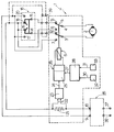
- the reference numeral 1 indicates, enclosed in broken outline, a safety circuit formed according to the present invention for the electrical control of a dc electric motor 2 operating, in a known way not illustrated, a window of a motor vehicle door.
- the supply terminals of this motor 2 are connected to respective central terminals 3 and 4 of a double switch 5 which is actuated by a coil of a relay 6.
- This switch 5 has a first pair 7 and 8 of change-over terminals which are connected to respective supply terminals 9 and 10 to which a dc supply voltage, such as a 12 volt supply, is conveniently applied.
- the double switch 5 further has a second pair of change-over terminals, 12 and 13, which are normally connected to the central terminals 3 and 4, in rest conditions of the relay 6, and are in turn connected to the central terminals 1 4 and 1 5 of a double switch 16 of known type for the control of the opening and closing respectively of the window.
- Such switch 16 has first change-over terminals 17 and 18 which are respectively connected to the supply terminals 9 and 10, and second change-over terminals 19 and 20 which are respectively connected to the supply terminals 10 and 9.
- the two movable contacts of the double switch 16 have an upper contact portion curved in opposite senses which, in the rest position, make contact with respective terminals 18 and 19 so as to form a short circuit with a braking function on the motor 2.
- a calibrated resistor 21 the voltage across the terminals of which is taken off by connections 22 to the input of a threshold circuit 23 conveniently including differential amplifiers with temperature compensation, which is operable to provide an output signal 24 when the value of the input voltage between the connections 22 is greater than a predetermined value .
- This signal 24 arrives at the input of a comparison circuit 25 which constitutes a first part of a timer unit 26.
- a comparison signal 27 provided by a circuit 28 to which are supplied two-signals 30 and 31 from two HALL effect sensors 32 and 33 respectively which detect the presence of the window in a predetermined region.
- these two sensors 32 and 33 are disposed close to the positions where the window is completely open and completely closed, for example, 200 mm and 4 mm from the upper stop of the window, and the circuit 28 is operable to provide the comparison signal 27 when the window is located in positions lying between these two end regions in which the sensors 22 and 23 are positioned.
- the signal 30 is present, which determines the comparison signal 27, and this signal 27 remains present until the window rises above the height of 4 mm from the upper stop at which the signal 31 is also present, which blocks the signal 27.
- the timer unit 26 is connected to control the activation of the relay 6.
- the user operates the double switch 16 in one sense or the other respectively to determine the connection of the terminals 17 and 18 or 19 and 20 to give rise to the supply of dc current in one directional sense or the other for the motor 2, and therefore control the opening or closing of the window.
- an obstacle to closure of the window itself becomes interposed and therefore exercises a force against the action of the motor 2
- the current absorbed by the motor 2 increases and therefore the voltage applied by the connections 22 to the input of the threshold circuit 23 also increases.
- This circuit 23 can conveniently be calibrated in such a way as to provide the output signal 24 when the force resisting the closure of the window is equal to or greater than 10 kilograms.
- the circuit 27 controls the timer unit 26 which therefore, for a time for example of 5 seconds, maintains the relay 6 activated so that the double switch 5 connects the central motor supply terminals 3 and 4 to the terminals 7 and 8 which are connected to the supply terminals 9 and 10 in such a way as to drive the motor 2 in a sense such as to lower the window.
- the safety circuit 1 forming the subject of the present invention is therefore particularly useful in combination with timer circuits for supply of the motor 2 which drives the window within a predetermined time period after the key has been removed from an operable position in the associated ignition switch of the vehicle, and in circuits including automatic operating means for such window winders, activated by a pulse control.
- operation of the motor 2 takes place in a way which is no longer subjected to the direct control of the position of the key in the ignition switch of the vehicle, so that it cannot be stopped immediately by withdrawing such key; this possible disadvantage is therefore overcome with this safety circuit of the present invention, which in the event of an obstacle to closure of the window being interposed automatically stops and reverses the movement of the window itself.
- a timer unit for example of the type described in the said Italian Patent Application No. 67520-A,/82 of 20 April 1982, interposed between a pair of supply terminals 36 and 37 connected to the battery of the vehicle, and the supply terminals 9 and 10.
- a circuit 39 for automatic operation of the windows under pulse control could on the other hand be conveniently disposed between the central terminals 14 and 15 of the double switch 16 and the terminals 12 and 13 of the switch 5.
- the circuit described, the subject of the present invention can be applied to the various control circuit configurations of the motor 2 described and illustrated by inserting the double switch 5 in the direct connection line to the motor driving the window winder and by inserting the resistor 21 in a connection traversed by the supply current to the motor operating the window downstream, naturally, of the timer circuit which operates the supply even in the absence of the key from the ignition switch of the vehicle.
- the described embodiments of the circuit of the present invention can be modified and varied without departing from the scope of the invention itself.
- the sensors 32 and 33 can be varied, for example, by including magnetic contacts or displacement sensors.
Applications Claiming Priority (2)
| Application Number | Priority Date | Filing Date | Title |
|---|---|---|---|
| IT67244/83A IT1171006B (it) | 1983-03-03 | 1983-03-03 | Circuito di sicurezza per il comando elettrico di un gruppo di aziona mento di alzacristalli su veicoli |
| IT6724483 | 1983-03-03 |
Publications (2)
| Publication Number | Publication Date |
|---|---|
| EP0118074A1 true EP0118074A1 (de) | 1984-09-12 |
| EP0118074B1 EP0118074B1 (de) | 1987-06-10 |
Family
ID=11300797
Family Applications (1)
| Application Number | Title | Priority Date | Filing Date |
|---|---|---|---|
| EP84101763A Expired EP0118074B1 (de) | 1983-03-03 | 1984-02-20 | Sicherheitsschaltung für die elektrische Steuerung eines elektrischen Scheibenantriebes eines Motorkraftfahrzeuges |
Country Status (4)
| Country | Link |
|---|---|
| EP (1) | EP0118074B1 (de) |
| DE (1) | DE3464183D1 (de) |
| ES (1) | ES8501046A1 (de) |
| IT (1) | IT1171006B (de) |
Cited By (6)
| Publication number | Priority date | Publication date | Assignee | Title |
|---|---|---|---|---|
| WO1988005221A1 (fr) * | 1987-01-08 | 1988-07-14 | Francois Jean Marc | Dispositif de serrure a haute securite a ouverture automatique au moyen d'un dispositif de decodage et de commande |
| FR2618176A1 (fr) * | 1987-07-17 | 1989-01-20 | Francois Jean Marc | Dispositif de serrure a haute securite a ouverture automatique au moyen d'un dispositif de decodage et de commande. |
| FR2643172A1 (fr) * | 1989-02-13 | 1990-08-17 | Jaeger | Detecteur d'obstacle de faible encombrement |
| GB2272484A (en) * | 1992-10-16 | 1994-05-18 | Dewhurst Plc | Method and apparatus of operating powered devices, for example, automatic doors |
| FR2731460A1 (fr) * | 1995-03-07 | 1996-09-13 | Valeo Electronique | Dispositif de detection de la position d'un ouvrant de vehicule automobile, dispositif de protection antipincement et systeme leve-vitre l'incorporant, ainsi que son procede de commande |
| EP2608705B1 (de) | 2010-08-27 | 2015-06-24 | Nestec S.A. | Gesteuerte motorisierte brüheinheit |
Citations (9)
| Publication number | Priority date | Publication date | Assignee | Title |
|---|---|---|---|---|
| US3513374A (en) * | 1968-09-05 | 1970-05-19 | Edward J Koment | Car window safety circuit |
| US3581174A (en) * | 1969-12-15 | 1971-05-25 | Gen Motors Corp | Automatic reversing circuit for a window regulator motor control system |
| US3617835A (en) * | 1969-09-29 | 1971-11-02 | Budd Co | Operating means for reciprocating mechanism |
| FR2400787A1 (fr) * | 1977-08-16 | 1979-03-16 | Daimler Benz Ag | Circuit de protection pour moteur a courant continu |
| GB2013428A (en) * | 1978-01-25 | 1979-08-08 | Tekron Patents Ltd | Circuits for electric window winders for vehicles |
| GB2053513A (en) * | 1979-07-04 | 1981-02-04 | Rau Swf Autozubehoer | Circuit arrangement for driving a movable element |
| DE3048989A1 (de) * | 1980-12-24 | 1982-07-15 | SWF-Spezialfabrik für Autozubehör Gustav Rau GmbH, 7120 Bietigheim-Bissingen | Schaltanordnung zum antrieb eines beweglichen elementes, insbesondere zum antrieb von scheiben o.dgl. in kraftfahrzeugen |
| EP0057338A2 (de) * | 1981-01-30 | 1982-08-11 | ACIERS ET OUTILLAGE PEUGEOT Société dite: | Steuergerät für den Antriebsmotor einer Schiebewand eines Kraftfahrzeuges, insbesondere für eine Fensterhebeanlage |
| FR2525270A1 (fr) * | 1982-04-20 | 1983-10-21 | Fiat Auto Spa | Circuit electrique de commande de leve-vitre pour vehicule |
-
1983
- 1983-03-03 IT IT67244/83A patent/IT1171006B/it active
-
1984
- 1984-02-20 EP EP84101763A patent/EP0118074B1/de not_active Expired
- 1984-02-20 DE DE8484101763T patent/DE3464183D1/de not_active Expired
- 1984-03-02 ES ES530255A patent/ES8501046A1/es not_active Expired
Patent Citations (9)
| Publication number | Priority date | Publication date | Assignee | Title |
|---|---|---|---|---|
| US3513374A (en) * | 1968-09-05 | 1970-05-19 | Edward J Koment | Car window safety circuit |
| US3617835A (en) * | 1969-09-29 | 1971-11-02 | Budd Co | Operating means for reciprocating mechanism |
| US3581174A (en) * | 1969-12-15 | 1971-05-25 | Gen Motors Corp | Automatic reversing circuit for a window regulator motor control system |
| FR2400787A1 (fr) * | 1977-08-16 | 1979-03-16 | Daimler Benz Ag | Circuit de protection pour moteur a courant continu |
| GB2013428A (en) * | 1978-01-25 | 1979-08-08 | Tekron Patents Ltd | Circuits for electric window winders for vehicles |
| GB2053513A (en) * | 1979-07-04 | 1981-02-04 | Rau Swf Autozubehoer | Circuit arrangement for driving a movable element |
| DE3048989A1 (de) * | 1980-12-24 | 1982-07-15 | SWF-Spezialfabrik für Autozubehör Gustav Rau GmbH, 7120 Bietigheim-Bissingen | Schaltanordnung zum antrieb eines beweglichen elementes, insbesondere zum antrieb von scheiben o.dgl. in kraftfahrzeugen |
| EP0057338A2 (de) * | 1981-01-30 | 1982-08-11 | ACIERS ET OUTILLAGE PEUGEOT Société dite: | Steuergerät für den Antriebsmotor einer Schiebewand eines Kraftfahrzeuges, insbesondere für eine Fensterhebeanlage |
| FR2525270A1 (fr) * | 1982-04-20 | 1983-10-21 | Fiat Auto Spa | Circuit electrique de commande de leve-vitre pour vehicule |
Cited By (9)
| Publication number | Priority date | Publication date | Assignee | Title |
|---|---|---|---|---|
| WO1988005221A1 (fr) * | 1987-01-08 | 1988-07-14 | Francois Jean Marc | Dispositif de serrure a haute securite a ouverture automatique au moyen d'un dispositif de decodage et de commande |
| FR2618176A1 (fr) * | 1987-07-17 | 1989-01-20 | Francois Jean Marc | Dispositif de serrure a haute securite a ouverture automatique au moyen d'un dispositif de decodage et de commande. |
| FR2643172A1 (fr) * | 1989-02-13 | 1990-08-17 | Jaeger | Detecteur d'obstacle de faible encombrement |
| EP0390618A1 (de) * | 1989-02-13 | 1990-10-03 | Jaeger | Hindernisdetektor |
| GB2272484A (en) * | 1992-10-16 | 1994-05-18 | Dewhurst Plc | Method and apparatus of operating powered devices, for example, automatic doors |
| FR2731460A1 (fr) * | 1995-03-07 | 1996-09-13 | Valeo Electronique | Dispositif de detection de la position d'un ouvrant de vehicule automobile, dispositif de protection antipincement et systeme leve-vitre l'incorporant, ainsi que son procede de commande |
| EP2608705B1 (de) | 2010-08-27 | 2015-06-24 | Nestec S.A. | Gesteuerte motorisierte brüheinheit |
| EP2608704B1 (de) | 2010-08-27 | 2016-06-22 | Nestec S.A. | Einfache motorisierte brüheinheit |
| US10285534B2 (en) | 2010-08-27 | 2019-05-14 | Nestec S.A. | Controlled motorized brewing unit |
Also Published As
| Publication number | Publication date |
|---|---|
| IT8367244A0 (it) | 1983-03-03 |
| ES530255A0 (es) | 1984-11-01 |
| IT1171006B (it) | 1987-06-10 |
| ES8501046A1 (es) | 1984-11-01 |
| EP0118074B1 (de) | 1987-06-10 |
| DE3464183D1 (en) | 1987-07-16 |
Similar Documents
| Publication | Publication Date | Title |
|---|---|---|
| US4394605A (en) | Load drive control system | |
| US4881018A (en) | Manually assistable electric driving device | |
| JP3656787B2 (ja) | 車輛用スライドドアの自動開閉装置 | |
| CA1167551A (en) | Door operation control apparatus | |
| US3513374A (en) | Car window safety circuit | |
| JPH06167167A (ja) | 車両の電気式開閉器のための安全装置 | |
| EP0118074A1 (de) | Sicherheitsschaltung für die elektrische Steuerung eines elektrischen Scheibenantriebes eines Motorkraftfahrzeuges | |
| JPH0657539B2 (ja) | 自動車の制御装置 | |
| US20040119433A1 (en) | Control device for opening/closing member | |
| KR100938134B1 (ko) | 전기로 작동 가능한 장치에서 역전 과정을 모니터링 및 제어를 위한 방법 | |
| ITTO950960A1 (it) | Dispositivo di comando per un alzavetro elettrico per autoveicoli. | |
| JP2962340B2 (ja) | パワーウインドウ装置 | |
| GB2199963A (en) | Control circuit for electrically operated windows | |
| JPH0510067A (ja) | ウインド開閉制御装置 | |
| US6002224A (en) | One touch vehicle window operating circuit | |
| JPH07115816B2 (ja) | エレベータの制御装置 | |
| JP3181461B2 (ja) | セーフテイ機能を備えたモータ駆動装置 | |
| EP0584033B1 (de) | Einklemmschutz für Fensterheber und Schiebedächer von Kraftfahrzeugen | |
| JPH0540221Y2 (de) | ||
| JP3747275B2 (ja) | オートスライドドア制御装置 | |
| JPH0746697Y2 (ja) | 自動ドア閉止装置 | |
| JPH0235828B2 (de) | ||
| JPH09328967A (ja) | パワーウインドウ装置 | |
| JPH0711221B2 (ja) | 警報回路を備えた自動ドア開閉装置 | |
| JPS6280974U (de) |
Legal Events
| Date | Code | Title | Description |
|---|---|---|---|
| PUAI | Public reference made under article 153(3) epc to a published international application that has entered the european phase |
Free format text: ORIGINAL CODE: 0009012 |
|
| AK | Designated contracting states |
Designated state(s): DE FR GB SE |
|
| 17P | Request for examination filed |
Effective date: 19850117 |
|
| 17Q | First examination report despatched |
Effective date: 19860128 |
|
| GRAA | (expected) grant |
Free format text: ORIGINAL CODE: 0009210 |
|
| AK | Designated contracting states |
Kind code of ref document: B1 Designated state(s): DE FR GB SE |
|
| REF | Corresponds to: |
Ref document number: 3464183 Country of ref document: DE Date of ref document: 19870716 |
|
| ET | Fr: translation filed | ||
| PLBE | No opposition filed within time limit |
Free format text: ORIGINAL CODE: 0009261 |
|
| STAA | Information on the status of an ep patent application or granted ep patent |
Free format text: STATUS: NO OPPOSITION FILED WITHIN TIME LIMIT |
|
| 26N | No opposition filed | ||
| PGFP | Annual fee paid to national office [announced via postgrant information from national office to epo] |
Ref country code: GB Payment date: 19930129 Year of fee payment: 10 |
|
| PG25 | Lapsed in a contracting state [announced via postgrant information from national office to epo] |
Ref country code: GB Effective date: 19940220 |
|
| GBPC | Gb: european patent ceased through non-payment of renewal fee |
Effective date: 19940220 |
|
| PGFP | Annual fee paid to national office [announced via postgrant information from national office to epo] |
Ref country code: SE Payment date: 19950127 Year of fee payment: 12 |
|
| EAL | Se: european patent in force in sweden |
Ref document number: 84101763.5 |
|
| PGFP | Annual fee paid to national office [announced via postgrant information from national office to epo] |
Ref country code: FR Payment date: 19950223 Year of fee payment: 12 |
|
| PGFP | Annual fee paid to national office [announced via postgrant information from national office to epo] |
Ref country code: DE Payment date: 19950227 Year of fee payment: 12 |
|
| PG25 | Lapsed in a contracting state [announced via postgrant information from national office to epo] |
Ref country code: SE Effective date: 19960221 |
|
| PG25 | Lapsed in a contracting state [announced via postgrant information from national office to epo] |
Ref country code: FR Effective date: 19961031 |
|
| PG25 | Lapsed in a contracting state [announced via postgrant information from national office to epo] |
Ref country code: DE Effective date: 19961101 |
|
| REG | Reference to a national code |
Ref country code: FR Ref legal event code: ST |