EP0118074A1 - A safety circuit for the electrical control of a motor vehicle electric window actuator unit - Google Patents
A safety circuit for the electrical control of a motor vehicle electric window actuator unit Download PDFInfo
- Publication number
- EP0118074A1 EP0118074A1 EP84101763A EP84101763A EP0118074A1 EP 0118074 A1 EP0118074 A1 EP 0118074A1 EP 84101763 A EP84101763 A EP 84101763A EP 84101763 A EP84101763 A EP 84101763A EP 0118074 A1 EP0118074 A1 EP 0118074A1
- Authority
- EP
- European Patent Office
- Prior art keywords
- fact
- window
- circuit according
- circuit
- unit
- Prior art date
- Legal status (The legal status is an assumption and is not a legal conclusion. Google has not performed a legal analysis and makes no representation as to the accuracy of the status listed.)
- Granted
Links
Images
Classifications
-
- H—ELECTRICITY
- H02—GENERATION; CONVERSION OR DISTRIBUTION OF ELECTRIC POWER
- H02H—EMERGENCY PROTECTIVE CIRCUIT ARRANGEMENTS
- H02H7/00—Emergency protective circuit arrangements specially adapted for specific types of electric machines or apparatus or for sectionalised protection of cable or line systems, and effecting automatic switching in the event of an undesired change from normal working conditions
- H02H7/08—Emergency protective circuit arrangements specially adapted for specific types of electric machines or apparatus or for sectionalised protection of cable or line systems, and effecting automatic switching in the event of an undesired change from normal working conditions for dynamo-electric motors
- H02H7/085—Emergency protective circuit arrangements specially adapted for specific types of electric machines or apparatus or for sectionalised protection of cable or line systems, and effecting automatic switching in the event of an undesired change from normal working conditions for dynamo-electric motors against excessive load
- H02H7/0851—Emergency protective circuit arrangements specially adapted for specific types of electric machines or apparatus or for sectionalised protection of cable or line systems, and effecting automatic switching in the event of an undesired change from normal working conditions for dynamo-electric motors against excessive load for motors actuating a movable member between two end positions, e.g. detecting an end position or obstruction by overload signal
Abstract
Description
- The present invention relates to a safety circuit for the electrical control of a window actuator unit on a motor vehicle. As is known, such electrical window actuator units are generally constituted by a dc electric motor which can be supplied from the battery of the vehicle, and by a double pole switch for controlling the closing and opening movements of the window. The movement of the window can only be stopped by the user acting on the switch.
- The object of the present invention is to provide a safety circuit for the electrical control of such window winder actuating units, which stops the closing movement of the window in the event of a force being applied against the movement of the window itself greater than a predetermined limit value, such as, for example, can happen in the event that a part of a person or a child remains trapped by the window itself, and then automatically causes the said window to descend to open and allow the immediate freeing of such a part.
- Other objects and advantages obtained with the safety circuit of the present invention, particularly in combination with timer control circuits which also allow the window actuator to be operated within a predetermined time after the key has been removed from an operative position in the associated ignition switch of the vehicle, or with automatic pulse actuating means of the window actuators, for example, of the type described in Italian Patent Application No. 67520-A/82 filed on 20 April 1982 by the same applicant, and the contents of which are incorporated herein by reference as far as the parts necessary are concerned, which will become apparent from the following description.
- According to the present invention there is provided a safety circuit for the electrical control of a window winder actuating unit on a motor vehicle, characterised by the fact that it includes means operable to detect the value of a parameter which is a function of the force applied against the action of the said unit and to reverse the sense of actuation of the said unit for values of said parameter greater than a predetermined limit.
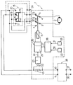
- For a better understanding of the present invention a particular embodiment will now be described, by way of a non-limitative example, with reference to the attached drawing which shows an electrical and block schematic diagram thereof.
- With reference to this drawing, the reference numeral 1 indicates, enclosed in broken outline, a safety circuit formed according to the present invention for the electrical control of a dc
electric motor 2 operating, in a known way not illustrated, a window of a motor vehicle door. The supply terminals of thismotor 2 are connected to respective central terminals 3 and 4 of a double switch 5 which is actuated by a coil of a relay 6. This switch 5 has a first pair 7 and 8 of change-over terminals which are connected torespective supply terminals terminals 17 and 18 which are respectively connected to thesupply terminals terminals 19 and 20 which are respectively connected to thesupply terminals respective terminals 18 and 19 so as to form a short circuit with a braking function on themotor 2. In series with the connection to thesupply terminal 10 in the safety circuit 1 there is disposed acalibrated resistor 21 the voltage across the terminals of which is taken off byconnections 22 to the input of athreshold circuit 23 conveniently including differential amplifiers with temperature compensation, which is operable to provide anoutput signal 24 when the value of the input voltage between theconnections 22 is greater than a predetermined value . Thissignal 24 arrives at the input of acomparison circuit 25 which constitutes a first part of atimer unit 26. At thiscomparison circuit 25 there also arrives acomparison signal 27 provided by acircuit 28 to which are supplied two-signals HALL effect sensors sensors circuit 28 is operable to provide thecomparison signal 27 when the window is located in positions lying between these two end regions in which thesensors signal 30 is present, which determines thecomparison signal 27, and thissignal 27 remains present until the window rises above the height of 4 mm from the upper stop at which thesignal 31 is also present, which blocks thesignal 27. Thetimer unit 26 is connected to control the activation of the relay 6. - The function of the safety circuit of the present invention described above is as follows.
- In conditions of normal use of the window winder, the user operates the double switch 16 in one sense or the other respectively to determine the connection of the
terminals motor 2, and therefore control the opening or closing of the window. If during the closing of the window an obstacle to closure of the window itself becomes interposed and therefore exercises a force against the action of themotor 2, the current absorbed by themotor 2 increases and therefore the voltage applied by theconnections 22 to the input of thethreshold circuit 23 also increases. Thiscircuit 23 can conveniently be calibrated in such a way as to provide theoutput signal 24 when the force resisting the closure of the window is equal to or greater than 10 kilograms. In these conditions, and if the window is in a position between the regions defined by the twosensors comparison signal 27 is present, thecircuit 27 controls thetimer unit 26 which therefore, for a time for example of 5 seconds, maintains the relay 6 activated so that the double switch 5 connects the central motor supply terminals 3 and 4 to the terminals 7 and 8 which are connected to thesupply terminals motor 2 in a sense such as to lower the window. In this way, upon the occurrence of this force against the action of themotor 2 above the predetermined limit, the reversal of the movement of themotor 2 takes place and the window is completely opened, thereby eliminating all the disadvantages or risks connected with an erroneous or careless operation of the switch 16 to actuate the window winder. - The safety circuit 1 forming the subject of the present invention is therefore particularly useful in combination with timer circuits for supply of the
motor 2 which drives the window within a predetermined time period after the key has been removed from an operable position in the associated ignition switch of the vehicle, and in circuits including automatic operating means for such window winders, activated by a pulse control. In fact, in such circuits operation of themotor 2 takes place in a way which is no longer subjected to the direct control of the position of the key in the ignition switch of the vehicle, so that it cannot be stopped immediately by withdrawing such key; this possible disadvantage is therefore overcome with this safety circuit of the present invention, which in the event of an obstacle to closure of the window being interposed automatically stops and reverses the movement of the window itself. In the drawing, there is therefore indicated, with thenumeral 35, a timer unit, for example of the type described in the said Italian Patent Application No. 67520-A,/82 of 20 April 1982, interposed between a pair ofsupply terminals supply terminals circuit 39 for automatic operation of the windows under pulse control, could on the other hand be conveniently disposed between thecentral terminals terminals 12 and 13 of the switch 5. In particular, still with reference to the said Italian Patent Application No. 67520-A/82, the circuit described, the subject of the present invention, can be applied to the various control circuit configurations of themotor 2 described and illustrated by inserting the double switch 5 in the direct connection line to the motor driving the window winder and by inserting theresistor 21 in a connection traversed by the supply current to the motor operating the window downstream, naturally, of the timer circuit which operates the supply even in the absence of the key from the ignition switch of the vehicle. - Finally, it is clear that the described embodiments of the circuit of the present invention can be modified and varied without departing from the scope of the invention itself. Among other things, the
sensors
Claims (14)
Applications Claiming Priority (2)
| Application Number | Priority Date | Filing Date | Title |
|---|---|---|---|
| IT67244/83A IT1171006B (en) | 1983-03-03 | 1983-03-03 | SAFETY CIRCUIT FOR THE ELECTRIC CONTROL OF A GROUP OF DRIVING WINDOWS ON VEHICLES |
| IT6724483 | 1983-03-03 |
Publications (2)
| Publication Number | Publication Date |
|---|---|
| EP0118074A1 true EP0118074A1 (en) | 1984-09-12 |
| EP0118074B1 EP0118074B1 (en) | 1987-06-10 |
Family
ID=11300797
Family Applications (1)
| Application Number | Title | Priority Date | Filing Date |
|---|---|---|---|
| EP84101763A Expired EP0118074B1 (en) | 1983-03-03 | 1984-02-20 | A safety circuit for the electrical control of a motor vehicle electric window actuator unit |
Country Status (4)
| Country | Link |
|---|---|
| EP (1) | EP0118074B1 (en) |
| DE (1) | DE3464183D1 (en) |
| ES (1) | ES8501046A1 (en) |
| IT (1) | IT1171006B (en) |
Cited By (6)
| Publication number | Priority date | Publication date | Assignee | Title |
|---|---|---|---|---|
| WO1988005221A1 (en) * | 1987-01-08 | 1988-07-14 | Francois Jean Marc | High security lock device with automatic opening by means of a decoding and control device |
| FR2618176A1 (en) * | 1987-07-17 | 1989-01-20 | Francois Jean Marc | High security lock device with automatic opening by means of a decoding and command device |
| FR2643172A1 (en) * | 1989-02-13 | 1990-08-17 | Jaeger | LOW SIZE OBSTACLE DETECTOR |
| GB2272484A (en) * | 1992-10-16 | 1994-05-18 | Dewhurst Plc | Method and apparatus of operating powered devices, for example, automatic doors |
| FR2731460A1 (en) * | 1995-03-07 | 1996-09-13 | Valeo Electronique | Device for detection of motorised window position in motor vehicle to avoid trapping person |
| EP2608705B1 (en) | 2010-08-27 | 2015-06-24 | Nestec S.A. | Controlled motorized brewing unit |
Citations (9)
| Publication number | Priority date | Publication date | Assignee | Title |
|---|---|---|---|---|
| US3513374A (en) * | 1968-09-05 | 1970-05-19 | Edward J Koment | Car window safety circuit |
| US3581174A (en) * | 1969-12-15 | 1971-05-25 | Gen Motors Corp | Automatic reversing circuit for a window regulator motor control system |
| US3617835A (en) * | 1969-09-29 | 1971-11-02 | Budd Co | Operating means for reciprocating mechanism |
| FR2400787A1 (en) * | 1977-08-16 | 1979-03-16 | Daimler Benz Ag | Overload protection circuit for small motor - consists of measuring resistor with level detector and time delay operating trip contact |
| GB2013428A (en) * | 1978-01-25 | 1979-08-08 | Tekron Patents Ltd | Circuits for electric window winders for vehicles |
| GB2053513A (en) * | 1979-07-04 | 1981-02-04 | Rau Swf Autozubehoer | Circuit arrangement for driving a movable element |
| DE3048989A1 (en) * | 1980-12-24 | 1982-07-15 | SWF-Spezialfabrik für Autozubehör Gustav Rau GmbH, 7120 Bietigheim-Bissingen | Drive circuit for bidirectional motor - is for side window of vehicle and has safety relay and fault monitor |
| EP0057338A2 (en) * | 1981-01-30 | 1982-08-11 | ACIERS ET OUTILLAGE PEUGEOT Société dite: | Control device for a powered sliding panel of a vehicle, especially for a window-lift |
| FR2525270A1 (en) * | 1982-04-20 | 1983-10-21 | Fiat Auto Spa | Electric control circuit for motor vehicle window winders - uses timing circuit to allow window winders to remain operational for period after ignition has been turned off |
-
1983
- 1983-03-03 IT IT67244/83A patent/IT1171006B/en active
-
1984
- 1984-02-20 EP EP84101763A patent/EP0118074B1/en not_active Expired
- 1984-02-20 DE DE8484101763T patent/DE3464183D1/en not_active Expired
- 1984-03-02 ES ES530255A patent/ES8501046A1/en not_active Expired
Patent Citations (9)
| Publication number | Priority date | Publication date | Assignee | Title |
|---|---|---|---|---|
| US3513374A (en) * | 1968-09-05 | 1970-05-19 | Edward J Koment | Car window safety circuit |
| US3617835A (en) * | 1969-09-29 | 1971-11-02 | Budd Co | Operating means for reciprocating mechanism |
| US3581174A (en) * | 1969-12-15 | 1971-05-25 | Gen Motors Corp | Automatic reversing circuit for a window regulator motor control system |
| FR2400787A1 (en) * | 1977-08-16 | 1979-03-16 | Daimler Benz Ag | Overload protection circuit for small motor - consists of measuring resistor with level detector and time delay operating trip contact |
| GB2013428A (en) * | 1978-01-25 | 1979-08-08 | Tekron Patents Ltd | Circuits for electric window winders for vehicles |
| GB2053513A (en) * | 1979-07-04 | 1981-02-04 | Rau Swf Autozubehoer | Circuit arrangement for driving a movable element |
| DE3048989A1 (en) * | 1980-12-24 | 1982-07-15 | SWF-Spezialfabrik für Autozubehör Gustav Rau GmbH, 7120 Bietigheim-Bissingen | Drive circuit for bidirectional motor - is for side window of vehicle and has safety relay and fault monitor |
| EP0057338A2 (en) * | 1981-01-30 | 1982-08-11 | ACIERS ET OUTILLAGE PEUGEOT Société dite: | Control device for a powered sliding panel of a vehicle, especially for a window-lift |
| FR2525270A1 (en) * | 1982-04-20 | 1983-10-21 | Fiat Auto Spa | Electric control circuit for motor vehicle window winders - uses timing circuit to allow window winders to remain operational for period after ignition has been turned off |
Cited By (9)
| Publication number | Priority date | Publication date | Assignee | Title |
|---|---|---|---|---|
| WO1988005221A1 (en) * | 1987-01-08 | 1988-07-14 | Francois Jean Marc | High security lock device with automatic opening by means of a decoding and control device |
| FR2618176A1 (en) * | 1987-07-17 | 1989-01-20 | Francois Jean Marc | High security lock device with automatic opening by means of a decoding and command device |
| FR2643172A1 (en) * | 1989-02-13 | 1990-08-17 | Jaeger | LOW SIZE OBSTACLE DETECTOR |
| EP0390618A1 (en) * | 1989-02-13 | 1990-10-03 | Jaeger | Obstacle detector |
| GB2272484A (en) * | 1992-10-16 | 1994-05-18 | Dewhurst Plc | Method and apparatus of operating powered devices, for example, automatic doors |
| FR2731460A1 (en) * | 1995-03-07 | 1996-09-13 | Valeo Electronique | Device for detection of motorised window position in motor vehicle to avoid trapping person |
| EP2608705B1 (en) | 2010-08-27 | 2015-06-24 | Nestec S.A. | Controlled motorized brewing unit |
| EP2608704B1 (en) | 2010-08-27 | 2016-06-22 | Nestec S.A. | Simple motorized brewing unit |
| US10285534B2 (en) | 2010-08-27 | 2019-05-14 | Nestec S.A. | Controlled motorized brewing unit |
Also Published As
| Publication number | Publication date |
|---|---|
| IT1171006B (en) | 1987-06-10 |
| EP0118074B1 (en) | 1987-06-10 |
| ES530255A0 (en) | 1984-11-01 |
| DE3464183D1 (en) | 1987-07-16 |
| ES8501046A1 (en) | 1984-11-01 |
| IT8367244A0 (en) | 1983-03-03 |
Similar Documents
| Publication | Publication Date | Title |
|---|---|---|
| US4394605A (en) | Load drive control system | |
| JP3656787B2 (en) | Automatic opening / closing device for vehicle sliding door | |
| CA1167551A (en) | Door operation control apparatus | |
| JPH06167167A (en) | Safety device for electric type switch of car | |
| EP0118074A1 (en) | A safety circuit for the electrical control of a motor vehicle electric window actuator unit | |
| JPH0657539B2 (en) | Car control equipment | |
| US20040119433A1 (en) | Control device for opening/closing member | |
| KR100938134B1 (en) | Method for monitoring and controlling the reversing process of electrically actuatable units | |
| ITTO950960A1 (en) | CONTROL DEVICE FOR AN ELECTRIC WINDOW FOR VEHICLES. | |
| JP2962340B2 (en) | Power window device | |
| GB2199963A (en) | Control circuit for electrically operated windows | |
| JPH0510067A (en) | Window opening and shutting controller | |
| US6002224A (en) | One touch vehicle window operating circuit | |
| JPH07115816B2 (en) | Elevator control equipment | |
| JP3181461B2 (en) | Motor drive device with safety function | |
| EP0584033B1 (en) | Antinipping protection system for window winders and sunroofs in automobile vehicles | |
| JPH0540221Y2 (en) | ||
| JP3747275B2 (en) | Automatic sliding door control device | |
| JPH0746697Y2 (en) | Automatic door closing device | |
| JP3185724B2 (en) | Drive | |
| JP3533653B2 (en) | Opening / closing body control device for vehicles | |
| JPH0235828B2 (en) | ||
| JPH09328967A (en) | Power window device | |
| JPS5931606B2 (en) | Control circuit for electric operating machine for wire rope type water gate drive | |
| JPH0711221B2 (en) | Automatic door opener with alarm circuit |
Legal Events
| Date | Code | Title | Description |
|---|---|---|---|
| PUAI | Public reference made under article 153(3) epc to a published international application that has entered the european phase |
Free format text: ORIGINAL CODE: 0009012 |
|
| AK | Designated contracting states |
Designated state(s): DE FR GB SE |
|
| 17P | Request for examination filed |
Effective date: 19850117 |
|
| 17Q | First examination report despatched |
Effective date: 19860128 |
|
| GRAA | (expected) grant |
Free format text: ORIGINAL CODE: 0009210 |
|
| AK | Designated contracting states |
Kind code of ref document: B1 Designated state(s): DE FR GB SE |
|
| REF | Corresponds to: |
Ref document number: 3464183 Country of ref document: DE Date of ref document: 19870716 |
|
| ET | Fr: translation filed | ||
| PLBE | No opposition filed within time limit |
Free format text: ORIGINAL CODE: 0009261 |
|
| STAA | Information on the status of an ep patent application or granted ep patent |
Free format text: STATUS: NO OPPOSITION FILED WITHIN TIME LIMIT |
|
| 26N | No opposition filed | ||
| PGFP | Annual fee paid to national office [announced via postgrant information from national office to epo] |
Ref country code: GB Payment date: 19930129 Year of fee payment: 10 |
|
| PG25 | Lapsed in a contracting state [announced via postgrant information from national office to epo] |
Ref country code: GB Effective date: 19940220 |
|
| GBPC | Gb: european patent ceased through non-payment of renewal fee |
Effective date: 19940220 |
|
| PGFP | Annual fee paid to national office [announced via postgrant information from national office to epo] |
Ref country code: SE Payment date: 19950127 Year of fee payment: 12 |
|
| EAL | Se: european patent in force in sweden |
Ref document number: 84101763.5 |
|
| PGFP | Annual fee paid to national office [announced via postgrant information from national office to epo] |
Ref country code: FR Payment date: 19950223 Year of fee payment: 12 |
|
| PGFP | Annual fee paid to national office [announced via postgrant information from national office to epo] |
Ref country code: DE Payment date: 19950227 Year of fee payment: 12 |
|
| PG25 | Lapsed in a contracting state [announced via postgrant information from national office to epo] |
Ref country code: SE Effective date: 19960221 |
|
| PG25 | Lapsed in a contracting state [announced via postgrant information from national office to epo] |
Ref country code: FR Effective date: 19961031 |
|
| PG25 | Lapsed in a contracting state [announced via postgrant information from national office to epo] |
Ref country code: DE Effective date: 19961101 |
|
| REG | Reference to a national code |
Ref country code: FR Ref legal event code: ST |