EP0115774B1 - Federnspanner - Google Patents
Federnspanner Download PDFInfo
- Publication number
- EP0115774B1 EP0115774B1 EP84100103A EP84100103A EP0115774B1 EP 0115774 B1 EP0115774 B1 EP 0115774B1 EP 84100103 A EP84100103 A EP 84100103A EP 84100103 A EP84100103 A EP 84100103A EP 0115774 B1 EP0115774 B1 EP 0115774B1
- Authority
- EP
- European Patent Office
- Prior art keywords
- spring
- threaded
- tube
- guide tube
- axial
- Prior art date
- Legal status (The legal status is an assumption and is not a legal conclusion. Google has not performed a legal analysis and makes no representation as to the accuracy of the status listed.)
- Expired
Links
- 238000004904 shortening Methods 0.000 claims description 4
- 238000004519 manufacturing process Methods 0.000 claims description 2
- 230000006835 compression Effects 0.000 abstract description 4
- 238000007906 compression Methods 0.000 abstract description 4
- 238000004804 winding Methods 0.000 description 4
- 230000004323 axial length Effects 0.000 description 2
- 238000003780 insertion Methods 0.000 description 2
- 230000037431 insertion Effects 0.000 description 2
- 238000006073 displacement reaction Methods 0.000 description 1
- 229910001651 emery Inorganic materials 0.000 description 1
- 239000004636 vulcanized rubber Substances 0.000 description 1
Images
Classifications
-
- B—PERFORMING OPERATIONS; TRANSPORTING
- B25—HAND TOOLS; PORTABLE POWER-DRIVEN TOOLS; MANIPULATORS
- B25B—TOOLS OR BENCH DEVICES NOT OTHERWISE PROVIDED FOR, FOR FASTENING, CONNECTING, DISENGAGING OR HOLDING
- B25B27/00—Hand tools, specially adapted for fitting together or separating parts or objects whether or not involving some deformation, not otherwise provided for
- B25B27/14—Hand tools, specially adapted for fitting together or separating parts or objects whether or not involving some deformation, not otherwise provided for for assembling objects other than by press fit or detaching same
- B25B27/30—Hand tools, specially adapted for fitting together or separating parts or objects whether or not involving some deformation, not otherwise provided for for assembling objects other than by press fit or detaching same positioning or withdrawing springs, e.g. coil or leaf springs
- B25B27/302—Hand tools, specially adapted for fitting together or separating parts or objects whether or not involving some deformation, not otherwise provided for for assembling objects other than by press fit or detaching same positioning or withdrawing springs, e.g. coil or leaf springs coil springs other than torsion coil springs
- B25B27/304—Hand tools, specially adapted for fitting together or separating parts or objects whether or not involving some deformation, not otherwise provided for for assembling objects other than by press fit or detaching same positioning or withdrawing springs, e.g. coil or leaf springs coil springs other than torsion coil springs by compressing coil springs
-
- B—PERFORMING OPERATIONS; TRANSPORTING
- B60—VEHICLES IN GENERAL
- B60G—VEHICLE SUSPENSION ARRANGEMENTS
- B60G2206/00—Indexing codes related to the manufacturing of suspensions: constructional features, the materials used, procedures or tools
- B60G2206/01—Constructional features of suspension elements, e.g. arms, dampers, springs
- B60G2206/90—Maintenance
- B60G2206/92—Tools or equipment used for assembling
- B60G2206/921—Coil spring compressor
Definitions
- the invention relates to a spring tensioner for large coil springs, especially for motor vehicle axle springs, consisting of two loose, plate-like pressure plates with helically wound ring surfaces as a support for the spring windings and each with a central push-through opening, and a threaded spindle which has a spindle head with a key profile and which is rotatably supported by means of an axial bearing on the pressure plate on the spindle head side, and from a threaded tube which has two diametrically opposite radial fingers at its end remote from the spindle head, through which the threaded tube can be brought into a rotationally fixed connection with the pressure plate remote from the spindle head and which has an internal thread which the threaded spindle underneath Shortening the pressure plate distance can be screwed in.
- the spindle head is rotatably seated by means of an annular flange on the outside of the pressure plate on the spindle head side near the edge of the central bore, the threaded spindle being able to rotate when the pressure plate is stationary.
- the pressure plate attached to the threaded tube which also has a central hole, is connected to the pressure plate in a rotationally fixed manner, namely by two diametrically opposed radial fingers, each of which grips between two pins arranged in pairs on the outside of the pressure plate and at the same time rest on the edge surface of the central hole .
- both pressure plates are provided with corresponding recesses for inserting the radial fingers of the threaded tube. Because in this known spring tensioner between the two pressure plates there is no protection against rotation, d. H. Because one pressure plate can rotate freely relative to the other and at most is inhibited by the friction on the threads of the spring in question, such spring tensioners cannot be used in practice for safety reasons. It has been shown that due to the slope of the spring coils, the risk is very great that the two pressure plates and with them the threaded spindle and the threaded pipe will automatically turn in the sense of relaxation of the compression spring and then quickly unscrew the threaded spindle from the threaded pipe , so that the compression spring is released in an uncontrolled manner. The possibility of countering this danger with a left-handed threaded spindle is therefore ruled out because there is another danger that the wrong direction of rotation is accidentally given to the threaded spindle, which can lead to the same dangerous accidents.
- the object of the invention is to improve a spring tensioner of the type mentioned in such a way that the two pressure plates, when they are in engagement with the threaded spindle or with the threaded tube and the threaded tube is screwed onto the threaded spindle, can no longer rotate relative to one another , whereby the handling should be as simple and safe as possible.
- Such a spring tensioner is not only just as easy to handle and use as the simpler spring tensioner of the type mentioned, but it also has the functionally decisive advantage that the two pressure plates cannot be rotated against each other in the tensioned state, but still axially let move relative to each other.
- the rotationally fixed connection of the two pressure plates in the tensioned state eliminates the very accident-prone danger that the spring will automatically turn out of the clamping position between the two pressure plates and / or the threaded connection between the threaded tube and the threaded spindle will loosen automatically.
- the threaded tube can be telescopically inserted into the guide tube.
- a further advantageous embodiment of the invention consists in that the threaded tube has at least one axial groove open at both ends in its outer surface, in which at least one groove spring rod or a sliding block which is fastened in or on the guide tube engages in an axially displaceable manner.
- the groove spring rod ends at least approximately in the plane in which the end of the threaded spindle lying opposite the spindle head lies. In this way it is ensured that the rotationally secure connection between the guide tube and the threaded tube is guaranteed over the entire working stroke length.
- Guide tube is about half as long as the threaded spindle
- another embodiment provides that the guide tube is at least approximately the same length as the threaded spindle.
- the last-mentioned embodiment offers greater torsional stability than the first-mentioned embodiment, in which the slot spring bars are extended beyond the length of the guide tube.
- the threaded tube has two diametrically opposed axial grooves in its outer surface, and the guide tube is provided with two groove spring bars engaging in these axial grooves.
- This double tongue and groove connection between the threaded tube and the guide tube is equally advantageous for the two aforementioned embodiments.
- the radial projection is arranged at the end of the threaded tube on the spindle head side and engages in an open end face of the guide tube, which extends approximately into the plane of the bearing surface.
- the radial projection is aligned with one of the radial fingers in the axial direction and the guide tube has a second axial slot diametrically opposite the guide slot and also open at the end for receiving the second radial finger diametrically opposite the radial projection.
- the second axial slot is shorter by the length of the threaded tube than the guide slot, which is arranged diametrically opposite and the length of which determines the maximum working stroke.
- both pressure plates are provided with central bores, the diameter of which is slightly larger than the outer diameter of the guide tube and if the radial fingers of the threaded tube each have a radial length which is greater than the radius of the central bore.
- a further advantageous embodiment of the spring tensioner is characterized in that the pressure plate which can be brought into connection with the threaded tube has diametrical depressions in the outer edge zone of its central bore, which are adapted in cross-section to the radial fingers and are used to hold them in a rotationally secure manner.
- the bearing surface of the guide tube is provided with at least one axial projection, which is assigned at least one radial recess in the wall of the central bore of the spindle head-side pressure plate, which fits in cross-section, in order to produce a rotationally fixed positive connection.
- both pressure plates can be of exactly the same design.
- the pressure plates In order to give the spring to be tensioned or the windings of the spring to be tensioned a good seat grip on the pressure plates, the pressure plates have ring sector-like support surfaces for the spring turns of the spring to be tensioned, which are covered with guide grooves and / or with a friction lining.
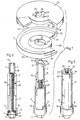
- the spring tensioner shown in the drawing consists essentially of two pressure plates 1 and 2, a threaded tube 3, a threaded spindle 4 which can be screwed into the threaded tube and a guide tube 5 in which the threaded spindle 4 is rotatably supported by means of an axial bearing 6.
- the threaded tube 3 has at its lower portion an internal thread 7 (FIG. 2) which extends approximately over a third of the total length of the threaded tube 3 and into which the threaded spindle 4 can be screwed.
- the axial bearing 6 Due to the axial bearing 6 is at its lower end with a flange-like support ring 8 and with an axially protruding from the guide tube 5, provided with a key profile spindle head 9 by means of a locking ring 11 seated in an annular groove 10 axially immovably in the guide ring 5.
- the guide tube 5 In the vicinity of the spindle head 9, the guide tube 5 is provided with a radially projecting, annular shoulder-like contact surface 12, which in turn has two diametrically opposite axial projections 13 and 14,
- the guide tube 5 is about half as long as the threaded spindle 4, but it is provided with two diametrically arranged groove spring bars 15 and 16 ending at least approximately in the same plane as the threaded spindle 4 , which engage in corresponding axial grooves 17 and 18, which are arranged in the outer surface of the threaded tube 3 when the threaded tube 3 is in engagement with the threaded spindle 4, as shown.
- the inner diameter of the guide tube 5 is so large that the threaded tube 3 can be telescopically immersed in the guide tube 5.
- the two slot spring bars 15 and 16 are designed so that they project radially inward over their entire length relative to the inner surface of the guide tube 5 by the groove depth of the two grooves 17 and 18.
- This tongue and groove connection ensures that the threaded tube 3 cannot rotate relative to the guide tube 5 as long as the threaded tube 3 with the threaded spindle 4 or as long as the slot spring bars 15 and 16 are in engagement with the slots 17 and 18 .
- two diametrically opposed radial fingers 19 and 20 are arranged at the upper end of the threaded tube 3.
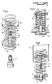
- the pressure plate 2 which rests on the support surface 12 when the spring tensioner is in use and is then near the spindle head, has a central bore 21, the diameter of which is slightly larger than the outer diameter of the guide tube 5 and smaller than the outer diameter of the support surface 12.
- the central bore 21 is also provided with two radial, groove-shaped recesses 22 and 23, which serve for the positive reception of the two axial projections 13 and 14.
- these recesses 22 and 23 are used to push the radial fingers 19 and 20 of the threaded tube 3. Accordingly, the cross-sectional profiles of the recesses 22 and 23 as well as the axial projections 13 and 14 and the radial projections 19 and 20 are matched to one another.
- the other pressure plate 1, which is to be brought into a rotationally fixed connection with the threaded tube 3, likewise has a central bore 24 which is provided with two recesses 22 'and 23' which are open diametrically to one another and are open continuously in the axial direction. These recesses 22 'and 23' also serve for the axial insertion of the radial fingers 19 and 20 of the threaded tube 3.
- the guide tube 5 is also provided with axial slots into which the two radial fingers 19 and 20 can penetrate axially, so the guide tube 5 has no influence on the clamping stroke limitation.
- Both pressure plates 1 and 2 are of substantially the same design, if one disregards the different design of the central bores 21 and 24 and the depressions 25 and 26 of the pressure plate 1, although there is also the possibility of designing the pressure plates identically in this respect, such as will be explained in more detail below.
- Both pressure plates have the shape of a plate-like circular disc, each with an egg NEM ring segment-like, extending about 70 to 90 ° cutout 28, which is used to perform a spring coil section.
- Their outer surfaces 29 and 30, which are arranged on the sides facing away from each other, are smooth.
- annular collar 31 or 32 running around the outer edge are helically wound annular surfaces 33 and 34, which in the exemplary embodiment shown in FIG.
- an emery strip can be provided and instead of a friction lining, the annular surfaces 33 and 34 could have one or more concentric grooves, which also center the one. can cause tensioned spring windings, be provided.
- FIG. 4 shows a helical spring 40 of a motor vehicle that has already been removed from a motor vehicle or has not yet been installed, in which the spring tensioner of FIG. 1 is already inserted ready for tensioning.
- the insertion was carried out in such a way that the pressure plates 1 and 2 were first inserted separately in the manner shown between two turns of the helical spring 40 from the side until they assumed an approximately concentric position with the spring turns.
- the clamping unit consisting of the threaded tube 3, the threaded spindle 4 and the guide tube 5 was first inserted in the axial direction through the lower pressure plate 2 and then through the upper pressure plate 1 around the two radial fingers 19 and 20 into the recesses 25 and 26 to set the upper pressure plate 1. It should be ensured that the axial projections 13 and 14 come into the recesses 22 and 23 of the lower pressure plate 2 and the edge of the central bore 21 is seated on the bearing surface 12.
- the threaded spindle 4 can be rotated by hand or by means of an impact screwdriver 41, so that there is a shortening of the plate spacing and the spring coils located between the pressure plates 1 and 2 are compressed.
- FIG. 6 shows how the coil spring 40 can also be used, for example, so that its upper end projects into a dome 44 present in the vehicle when the coil spring 40 is relaxed.
- the guide tube 5 and the threaded tube 3 are detached from the two pressure plates 1 and 2 in the manner described above. Then, while the lower pressure plate 2 can simply be pulled out of the coil spring 40 laterally, it is necessary to turn the upper pressure plate downward along the turns so that it can also be removed laterally when it has left the dome 44.
- a guide tube 5 ' is shown, which is the same length as the threaded spindle 4 and its slot spring bars 15' and 16 'are fully integrated into the wall.
- This guide tube 5 can be easily combined with the threaded tube 3 of FIGS. 1 and 2. So that the maximum working stroke is not limited by the upper end ring surface 27 ', two axial slots 45 and 46 are provided which are offset by 90 ° to the slot spring bars 15' and 16 ', i.e. diametrically opposite, into which the two radial fingers 19 and 20 of the Threaded tube 3 can penetrate, which are each arranged at 90 ° to the axial grooves 17 and 18. Because, in this embodiment of the guide tube 5 ', the slot spring bars 15' and 16 'are integrated into the wall over their entire length, they have greater stability against rotation than the slot guide bars 15 and 16, which are extended beyond the length of the guide tube 5.
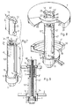
- a guide tube 5/1 is provided which, like the guide tubes 5 and 5 ' is provided with a support surface 12 and two axial projections 13 and 14 and in which the threaded spindle 4 is rotatably supported in the same manner.
- the guide tube 5/1 has the same length as the threaded spindle 4, ie its upper end face 27 'lies at least approximately in the same plane as the end face of the threaded spindle 4.
- the guide tube 5/1 has an axial guide slot 47 which extends into the vicinity of the bearing surface 12 and the the upper end face 27 'is open.
- the threaded tube 3/1 is provided at its lower end with a radial projection 3 ', which is aligned in the axial direction with the radial finger and which is intended to be axially displaceably guided in the guide slot 47 of the guide tube 5/1 and the non-rotatable connection between the threaded pipe 3/1 and the guide tube 5/1.
- the inner diameter of the guide tube 5/1 and the outer diameter of the threaded tube 3/1 are matched to one another so that the threaded tube 3/1 can be telescopically immersed in the guide tube 5/1.
- a second axial slot 48 open at the top is arranged diametrically to the guide slot 47.
- the length 12 of the axial slot 48 is about the length 11 of the threaded tube 3/1 shorter than the length 13 of the guide slot 47 in order not to unduly weaken the torsional stability of the guide tube 5/1.
- this pressure plate 1' is provided with a central bore 24 ', the diameter of which is slight is larger than the outer diameter of the guide tube 5/1, so that the guide tube 5/1 can penetrate into this central bore 24 '.
- the two pressure plates 1 'and 2' which have the same shape as the pressure plates 1 and 2 of the embodiment of FIGS. 1 and 2, have instead of the friction linings 35 and 36 each have concentric guide grooves 49 in which the spring turns, which come into direct contact with the pressure plates 1 'and 2', receive a good centering radial guide, which is important for a uniform straight-line tensioning of the coil spring 40.
- the lower pressure plate 2' either in the manner shown in Fig.8 of the support surface 12 can be seated or rotated by 90 °, in which case the two axial projections 13 and 14 would engage in the recesses 25 and 26 which are also present. In this case, the lower pressure plate 2 'would then be supported on the end faces of the axial projections 13 and 14 and not on the contact surface 12.
Landscapes
- Engineering & Computer Science (AREA)
- Mechanical Engineering (AREA)
- Vehicle Body Suspensions (AREA)
- Devices For Conveying Motion By Means Of Endless Flexible Members (AREA)
- Hand Tools For Fitting Together And Separating, Or Other Hand Tools (AREA)
- Automobile Manufacture Line, Endless Track Vehicle, Trailer (AREA)
- Springs (AREA)
- Chair Legs, Seat Parts, And Backrests (AREA)
- Surgical Instruments (AREA)
- Compressors, Vaccum Pumps And Other Relevant Systems (AREA)
- Fluid-Damping Devices (AREA)
Priority Applications (1)
| Application Number | Priority Date | Filing Date | Title |
|---|---|---|---|
| AT84100103T ATE19984T1 (de) | 1983-02-09 | 1984-01-07 | Federnspanner. |
Applications Claiming Priority (2)
| Application Number | Priority Date | Filing Date | Title |
|---|---|---|---|
| DE3304321 | 1983-02-09 | ||
| DE3304321A DE3304321C2 (de) | 1983-02-09 | 1983-02-09 | Federnspanner |
Publications (2)
| Publication Number | Publication Date |
|---|---|
| EP0115774A1 EP0115774A1 (de) | 1984-08-15 |
| EP0115774B1 true EP0115774B1 (de) | 1986-05-28 |
Family
ID=6190341
Family Applications (1)
| Application Number | Title | Priority Date | Filing Date |
|---|---|---|---|
| EP84100103A Expired EP0115774B1 (de) | 1983-02-09 | 1984-01-07 | Federnspanner |
Country Status (7)
| Country | Link |
|---|---|
| US (1) | US4527782A (cg-RX-API-DMAC7.html) |
| EP (1) | EP0115774B1 (cg-RX-API-DMAC7.html) |
| JP (1) | JPS59167308A (cg-RX-API-DMAC7.html) |
| AT (1) | ATE19984T1 (cg-RX-API-DMAC7.html) |
| AU (1) | AU564814B2 (cg-RX-API-DMAC7.html) |
| CA (1) | CA1215086A (cg-RX-API-DMAC7.html) |
| DE (1) | DE3304321C2 (cg-RX-API-DMAC7.html) |
Cited By (2)
| Publication number | Priority date | Publication date | Assignee | Title |
|---|---|---|---|---|
| DE10247643A1 (de) * | 2002-10-11 | 2004-04-22 | Audi Ag | Halterung für Kraftfahrzeugachsfedern, wie Schraubenfedern |
| DE10361597B3 (de) * | 2003-12-24 | 2005-06-30 | Klann-Spezial-Werkzeugbau-Gmbh | System zum Spannen einer Schraubenfeder |
Families Citing this family (19)
| Publication number | Priority date | Publication date | Assignee | Title |
|---|---|---|---|---|
| DE3733723A1 (de) * | 1986-10-10 | 1988-04-21 | Kleinbongartz & Kaiser Werkzeu | Federnspanner |
| DE3720018C2 (de) * | 1986-12-11 | 1988-09-29 | Horst Klann | Federnspanner |
| NL8700248A (nl) * | 1987-02-02 | 1988-09-01 | Ir Gerrit Schmidt | Veerpakket voor een voertuig en werkwijze voor de montage van een dergelijk veerpakket. |
| DE8708476U1 (de) * | 1987-06-16 | 1987-08-06 | Klann, Horst, 7730 Villingen-Schwenningen | Federnspanner |
| DE3823041C1 (cg-RX-API-DMAC7.html) * | 1988-07-07 | 1989-10-12 | Horst 7730 Villingen-Schwenningen De Klann | |
| FR2647045B1 (fr) * | 1989-05-19 | 1994-04-08 | Mecanique Energetique | Dispositif de montage et demontage de ressorts helicoidaux |
| DE4211176C2 (de) * | 1992-04-03 | 1998-07-23 | Porsche Ag | Lagerung für ein Federbein eines Kraftfahrzeuges |
| DE9400972U1 (de) * | 1994-01-21 | 1994-03-17 | Klann, Horst, 78052 Villingen-Schwenningen | Kunststoffauflage für die Greiferelemente eines Federspanners |
| DE19631524C1 (de) * | 1996-08-03 | 1997-11-27 | Angelika Weishaar | Konsolfederspanner |
| DE20119267U1 (de) | 2001-11-27 | 2002-02-21 | Klann Tools Ltd., Oxfordshire | Exzenter-Druckplatten für Federspanner |
| US20040169323A1 (en) * | 2003-02-28 | 2004-09-02 | Bottene Marlon V. | MacPherson strut spring coil mounts |
| US20040169324A1 (en) * | 2003-02-28 | 2004-09-02 | Bottene Marlon V. | Strut spring seat |
| DE202006010137U1 (de) * | 2006-06-28 | 2006-09-28 | Klann-Spezial-Werkzeugbau-Gmbh | Vorrichtung zum Ausrichten einer Druckplatte eines Federspanners |
| US7510175B2 (en) * | 2007-01-29 | 2009-03-31 | Mei Hwa Technology Corp. | Assisting ejection device for hatch of hatchback |
| US8112856B2 (en) * | 2008-08-05 | 2012-02-14 | Yakita Metal Industry Co., Ltd. | Clamp of anti-vibration spring |
| JP6167705B2 (ja) * | 2013-07-11 | 2017-07-26 | 株式会社Ihi | 触媒支持装置取付治具 |
| DE102021120678A1 (de) | 2021-08-09 | 2023-02-09 | GEDORE Holding GmbH | Federspanner |
| FR3139033B1 (fr) * | 2022-08-30 | 2024-07-26 | Psa Automobiles Sa | Coupelle de compression d’un amortisseur de véhicule automobile |
| CN117300591B (zh) * | 2023-06-02 | 2024-05-24 | 广州奥图弹簧有限公司 | 一种弹簧入管设备及弹簧热强压方法 |
Family Cites Families (9)
| Publication number | Priority date | Publication date | Assignee | Title |
|---|---|---|---|---|
| FR344191A (fr) * | 1904-06-21 | 1904-10-26 | Julien Francois Mamet | Tige élastique pour le support de la selle ou du guidon des bicyclettes, motocyclettes, tricycles |
| GB916897A (en) * | 1961-08-24 | 1963-01-30 | Leonard Salvatore Suozzo | Floor type spring support |
| US3256594A (en) * | 1964-07-10 | 1966-06-21 | Eugene C Howard | Spring compressing tool |
| US3747895A (en) * | 1971-11-04 | 1973-07-24 | M Martin | Spring extender |
| GB1437455A (en) * | 1973-04-30 | 1976-05-26 | Girling Ltd | Spring compression tools |
| JPS5036200U (cg-RX-API-DMAC7.html) * | 1973-07-28 | 1975-04-16 | ||
| DE2703048A1 (de) * | 1977-01-26 | 1978-08-10 | Adolf Woitzik | Federspanner zum spannen der vorder- und hinterfeder an kraftfahrzeugen |
| DE7800663U1 (de) * | 1978-01-11 | 1978-04-27 | Klann, Horst, 7730 Villingen | Vorrichtung zum spannen grosser schrauben-druckfedern |
| DE2813381C2 (de) * | 1978-03-28 | 1982-12-30 | Horst 7730 Villingen-Schwenningen Klann | Druckfedernspanner |
-
1983
- 1983-02-09 DE DE3304321A patent/DE3304321C2/de not_active Expired
-
1984
- 1984-01-07 EP EP84100103A patent/EP0115774B1/de not_active Expired
- 1984-01-07 AT AT84100103T patent/ATE19984T1/de active
- 1984-01-20 US US06/572,517 patent/US4527782A/en not_active Expired - Lifetime
- 1984-02-08 CA CA000447053A patent/CA1215086A/en not_active Expired
- 1984-02-08 AU AU24263/84A patent/AU564814B2/en not_active Ceased
- 1984-02-09 JP JP59020933A patent/JPS59167308A/ja active Granted
Cited By (3)
| Publication number | Priority date | Publication date | Assignee | Title |
|---|---|---|---|---|
| DE10247643A1 (de) * | 2002-10-11 | 2004-04-22 | Audi Ag | Halterung für Kraftfahrzeugachsfedern, wie Schraubenfedern |
| DE10247643B4 (de) * | 2002-10-11 | 2004-09-23 | Audi Ag | Halterung für Schraubenfedern an Kraftfahrzeugachsen |
| DE10361597B3 (de) * | 2003-12-24 | 2005-06-30 | Klann-Spezial-Werkzeugbau-Gmbh | System zum Spannen einer Schraubenfeder |
Also Published As
| Publication number | Publication date |
|---|---|
| JPH059235B2 (cg-RX-API-DMAC7.html) | 1993-02-04 |
| JPS59167308A (ja) | 1984-09-20 |
| US4527782A (en) | 1985-07-09 |
| AU2426384A (en) | 1984-08-16 |
| ATE19984T1 (de) | 1986-06-15 |
| AU564814B2 (en) | 1987-08-27 |
| CA1215086A (en) | 1986-12-09 |
| DE3304321C2 (de) | 1985-02-21 |
| DE3304321A1 (de) | 1984-08-16 |
| EP0115774A1 (de) | 1984-08-15 |
Similar Documents
| Publication | Publication Date | Title |
|---|---|---|
| EP0115774B1 (de) | Federnspanner | |
| DE3507740C2 (de) | Selbstverriegelnde, lösbare Verriegelungsmutter | |
| EP0271782B1 (de) | Federnspanner | |
| DE2726452A1 (de) | Antrieb fuer eine lamellenjalousie | |
| DE1928490B2 (de) | Schloßmutter | |
| DE2700605A1 (de) | Drehsicherung fuer eine gewindeverbindung | |
| DE3739663C2 (cg-RX-API-DMAC7.html) | ||
| EP1109983A1 (de) | Anschraubscharnier mit raststellung | |
| EP0275441B1 (de) | Spannvorrichtung | |
| EP0555633A1 (de) | Türdrückergarnitur | |
| DE3038774A1 (de) | Schraubtrieb mit doppelmutter | |
| DE3243948C2 (cg-RX-API-DMAC7.html) | ||
| DE2216588C3 (de) | Elektrisch angetriebener Dosenöffner | |
| DE3733723C2 (cg-RX-API-DMAC7.html) | ||
| EP4047219B1 (de) | Montage-einheit mit zumindest einer montageschiene sowie wenigstens einer halteklammer | |
| DE29702673U1 (de) | Federspanner zum Spannen von Schraubenfedern mit zwei Druckplatten | |
| DE29505752U1 (de) | Vorrichtung zum Verbinden von Platten mittels Verschraubung | |
| DE2806417C2 (de) | Mehrkant-Schloßstift | |
| DE3318745C2 (de) | Hobelmaschine, insbesondere Handhobel | |
| DE4316808C2 (de) | Spannstück für Rohrelemente | |
| DE202020100426U1 (de) | Zug-Druck-Stange | |
| DE2747152C3 (de) | Vielfachdrehumschalter | |
| DE8303510U1 (de) | Federnspanner | |
| DE1188378B (de) | Befestigungsvorrichtung | |
| DE1502570C3 (de) | Schleifwerkzeug mit Antriebsspindel |
Legal Events
| Date | Code | Title | Description |
|---|---|---|---|
| PUAI | Public reference made under article 153(3) epc to a published international application that has entered the european phase |
Free format text: ORIGINAL CODE: 0009012 |
|
| AK | Designated contracting states |
Designated state(s): AT BE CH FR GB IT LI NL SE |
|
| 17P | Request for examination filed |
Effective date: 19840613 |
|
| GRAA | (expected) grant |
Free format text: ORIGINAL CODE: 0009210 |
|
| AK | Designated contracting states |
Kind code of ref document: B1 Designated state(s): AT BE CH FR GB IT LI NL SE |
|
| REF | Corresponds to: |
Ref document number: 19984 Country of ref document: AT Date of ref document: 19860615 Kind code of ref document: T |
|
| ET | Fr: translation filed | ||
| ITF | It: translation for a ep patent filed | ||
| PLBI | Opposition filed |
Free format text: ORIGINAL CODE: 0009260 |
|
| 26 | Opposition filed |
Opponent name: KLEINBONGARTZ & KAISER Effective date: 19870128 |
|
| NLR1 | Nl: opposition has been filed with the epo |
Opponent name: KLEINBONGARTZ & KAISER |
|
| PLBN | Opposition rejected |
Free format text: ORIGINAL CODE: 0009273 |
|
| STAA | Information on the status of an ep patent application or granted ep patent |
Free format text: STATUS: OPPOSITION REJECTED |
|
| 27O | Opposition rejected |
Effective date: 19900425 |
|
| NLR2 | Nl: decision of opposition | ||
| PGFP | Annual fee paid to national office [announced via postgrant information from national office to epo] |
Ref country code: BE Payment date: 19921127 Year of fee payment: 10 |
|
| PGFP | Annual fee paid to national office [announced via postgrant information from national office to epo] |
Ref country code: AT Payment date: 19921217 Year of fee payment: 10 |
|
| PGFP | Annual fee paid to national office [announced via postgrant information from national office to epo] |
Ref country code: CH Payment date: 19930119 Year of fee payment: 10 |
|
| ITTA | It: last paid annual fee | ||
| PGFP | Annual fee paid to national office [announced via postgrant information from national office to epo] |
Ref country code: NL Payment date: 19930131 Year of fee payment: 10 |
|
| PGFP | Annual fee paid to national office [announced via postgrant information from national office to epo] |
Ref country code: SE Payment date: 19931203 Year of fee payment: 11 |
|
| PG25 | Lapsed in a contracting state [announced via postgrant information from national office to epo] |
Ref country code: AT Effective date: 19940107 |
|
| PG25 | Lapsed in a contracting state [announced via postgrant information from national office to epo] |
Ref country code: LI Effective date: 19940131 Ref country code: CH Effective date: 19940131 Ref country code: BE Effective date: 19940131 |
|
| BERE | Be: lapsed |
Owner name: KLANN HORST Effective date: 19940131 |
|
| PG25 | Lapsed in a contracting state [announced via postgrant information from national office to epo] |
Ref country code: NL Effective date: 19940801 |
|
| NLV4 | Nl: lapsed or anulled due to non-payment of the annual fee | ||
| REG | Reference to a national code |
Ref country code: CH Ref legal event code: PL |
|
| PG25 | Lapsed in a contracting state [announced via postgrant information from national office to epo] |
Ref country code: SE Effective date: 19950108 |
|
| PGFP | Annual fee paid to national office [announced via postgrant information from national office to epo] |
Ref country code: FR Payment date: 19950125 Year of fee payment: 12 |
|
| EAL | Se: european patent in force in sweden |
Ref document number: 84100103.5 |
|
| EUG | Se: european patent has lapsed |
Ref document number: 84100103.5 |
|
| PG25 | Lapsed in a contracting state [announced via postgrant information from national office to epo] |
Ref country code: FR Effective date: 19960930 |
|
| REG | Reference to a national code |
Ref country code: FR Ref legal event code: ST |
|
| PGFP | Annual fee paid to national office [announced via postgrant information from national office to epo] |
Ref country code: GB Payment date: 19971223 Year of fee payment: 15 |
|
| PG25 | Lapsed in a contracting state [announced via postgrant information from national office to epo] |
Ref country code: GB Free format text: LAPSE BECAUSE OF NON-PAYMENT OF DUE FEES Effective date: 19990107 |
|
| GBPC | Gb: european patent ceased through non-payment of renewal fee |
Effective date: 19990107 |
|
| APAH | Appeal reference modified |
Free format text: ORIGINAL CODE: EPIDOSCREFNO |