EP0115774B1 - Spring compressor - Google Patents
Spring compressor Download PDFInfo
- Publication number
- EP0115774B1 EP0115774B1 EP84100103A EP84100103A EP0115774B1 EP 0115774 B1 EP0115774 B1 EP 0115774B1 EP 84100103 A EP84100103 A EP 84100103A EP 84100103 A EP84100103 A EP 84100103A EP 0115774 B1 EP0115774 B1 EP 0115774B1
- Authority
- EP
- European Patent Office
- Prior art keywords
- spring
- threaded
- tube
- guide tube
- axial
- Prior art date
- Legal status (The legal status is an assumption and is not a legal conclusion. Google has not performed a legal analysis and makes no representation as to the accuracy of the status listed.)
- Expired
Links
- 238000004904 shortening Methods 0.000 claims description 4
- 238000004519 manufacturing process Methods 0.000 claims description 2
- 230000006835 compression Effects 0.000 abstract description 4
- 238000007906 compression Methods 0.000 abstract description 4
- 238000004804 winding Methods 0.000 description 4
- 230000004323 axial length Effects 0.000 description 2
- 238000003780 insertion Methods 0.000 description 2
- 230000037431 insertion Effects 0.000 description 2
- 238000006073 displacement reaction Methods 0.000 description 1
- 229910001651 emery Inorganic materials 0.000 description 1
- 239000004636 vulcanized rubber Substances 0.000 description 1
Images
Classifications
-
- B—PERFORMING OPERATIONS; TRANSPORTING
- B25—HAND TOOLS; PORTABLE POWER-DRIVEN TOOLS; MANIPULATORS
- B25B—TOOLS OR BENCH DEVICES NOT OTHERWISE PROVIDED FOR, FOR FASTENING, CONNECTING, DISENGAGING OR HOLDING
- B25B27/00—Hand tools, specially adapted for fitting together or separating parts or objects whether or not involving some deformation, not otherwise provided for
- B25B27/14—Hand tools, specially adapted for fitting together or separating parts or objects whether or not involving some deformation, not otherwise provided for for assembling objects other than by press fit or detaching same
- B25B27/30—Hand tools, specially adapted for fitting together or separating parts or objects whether or not involving some deformation, not otherwise provided for for assembling objects other than by press fit or detaching same positioning or withdrawing springs, e.g. coil or leaf springs
- B25B27/302—Hand tools, specially adapted for fitting together or separating parts or objects whether or not involving some deformation, not otherwise provided for for assembling objects other than by press fit or detaching same positioning or withdrawing springs, e.g. coil or leaf springs coil springs other than torsion coil springs
- B25B27/304—Hand tools, specially adapted for fitting together or separating parts or objects whether or not involving some deformation, not otherwise provided for for assembling objects other than by press fit or detaching same positioning or withdrawing springs, e.g. coil or leaf springs coil springs other than torsion coil springs by compressing coil springs
-
- B—PERFORMING OPERATIONS; TRANSPORTING
- B60—VEHICLES IN GENERAL
- B60G—VEHICLE SUSPENSION ARRANGEMENTS
- B60G2206/00—Indexing codes related to the manufacturing of suspensions: constructional features, the materials used, procedures or tools
- B60G2206/01—Constructional features of suspension elements, e.g. arms, dampers, springs
- B60G2206/90—Maintenance
- B60G2206/92—Tools or equipment used for assembling
- B60G2206/921—Coil spring compressor
Definitions
- the invention relates to a spring tensioner for large coil springs, especially for motor vehicle axle springs, consisting of two loose, plate-like pressure plates with helically wound ring surfaces as a support for the spring windings and each with a central push-through opening, and a threaded spindle which has a spindle head with a key profile and which is rotatably supported by means of an axial bearing on the pressure plate on the spindle head side, and from a threaded tube which has two diametrically opposite radial fingers at its end remote from the spindle head, through which the threaded tube can be brought into a rotationally fixed connection with the pressure plate remote from the spindle head and which has an internal thread which the threaded spindle underneath Shortening the pressure plate distance can be screwed in.
- the spindle head is rotatably seated by means of an annular flange on the outside of the pressure plate on the spindle head side near the edge of the central bore, the threaded spindle being able to rotate when the pressure plate is stationary.
- the pressure plate attached to the threaded tube which also has a central hole, is connected to the pressure plate in a rotationally fixed manner, namely by two diametrically opposed radial fingers, each of which grips between two pins arranged in pairs on the outside of the pressure plate and at the same time rest on the edge surface of the central hole .
- both pressure plates are provided with corresponding recesses for inserting the radial fingers of the threaded tube. Because in this known spring tensioner between the two pressure plates there is no protection against rotation, d. H. Because one pressure plate can rotate freely relative to the other and at most is inhibited by the friction on the threads of the spring in question, such spring tensioners cannot be used in practice for safety reasons. It has been shown that due to the slope of the spring coils, the risk is very great that the two pressure plates and with them the threaded spindle and the threaded pipe will automatically turn in the sense of relaxation of the compression spring and then quickly unscrew the threaded spindle from the threaded pipe , so that the compression spring is released in an uncontrolled manner. The possibility of countering this danger with a left-handed threaded spindle is therefore ruled out because there is another danger that the wrong direction of rotation is accidentally given to the threaded spindle, which can lead to the same dangerous accidents.
- the object of the invention is to improve a spring tensioner of the type mentioned in such a way that the two pressure plates, when they are in engagement with the threaded spindle or with the threaded tube and the threaded tube is screwed onto the threaded spindle, can no longer rotate relative to one another , whereby the handling should be as simple and safe as possible.
- Such a spring tensioner is not only just as easy to handle and use as the simpler spring tensioner of the type mentioned, but it also has the functionally decisive advantage that the two pressure plates cannot be rotated against each other in the tensioned state, but still axially let move relative to each other.
- the rotationally fixed connection of the two pressure plates in the tensioned state eliminates the very accident-prone danger that the spring will automatically turn out of the clamping position between the two pressure plates and / or the threaded connection between the threaded tube and the threaded spindle will loosen automatically.
- the threaded tube can be telescopically inserted into the guide tube.
- a further advantageous embodiment of the invention consists in that the threaded tube has at least one axial groove open at both ends in its outer surface, in which at least one groove spring rod or a sliding block which is fastened in or on the guide tube engages in an axially displaceable manner.
- the groove spring rod ends at least approximately in the plane in which the end of the threaded spindle lying opposite the spindle head lies. In this way it is ensured that the rotationally secure connection between the guide tube and the threaded tube is guaranteed over the entire working stroke length.
- Guide tube is about half as long as the threaded spindle
- another embodiment provides that the guide tube is at least approximately the same length as the threaded spindle.
- the last-mentioned embodiment offers greater torsional stability than the first-mentioned embodiment, in which the slot spring bars are extended beyond the length of the guide tube.
- the threaded tube has two diametrically opposed axial grooves in its outer surface, and the guide tube is provided with two groove spring bars engaging in these axial grooves.
- This double tongue and groove connection between the threaded tube and the guide tube is equally advantageous for the two aforementioned embodiments.
- the radial projection is arranged at the end of the threaded tube on the spindle head side and engages in an open end face of the guide tube, which extends approximately into the plane of the bearing surface.
- the radial projection is aligned with one of the radial fingers in the axial direction and the guide tube has a second axial slot diametrically opposite the guide slot and also open at the end for receiving the second radial finger diametrically opposite the radial projection.
- the second axial slot is shorter by the length of the threaded tube than the guide slot, which is arranged diametrically opposite and the length of which determines the maximum working stroke.
- both pressure plates are provided with central bores, the diameter of which is slightly larger than the outer diameter of the guide tube and if the radial fingers of the threaded tube each have a radial length which is greater than the radius of the central bore.
- a further advantageous embodiment of the spring tensioner is characterized in that the pressure plate which can be brought into connection with the threaded tube has diametrical depressions in the outer edge zone of its central bore, which are adapted in cross-section to the radial fingers and are used to hold them in a rotationally secure manner.
- the bearing surface of the guide tube is provided with at least one axial projection, which is assigned at least one radial recess in the wall of the central bore of the spindle head-side pressure plate, which fits in cross-section, in order to produce a rotationally fixed positive connection.
- both pressure plates can be of exactly the same design.
- the pressure plates In order to give the spring to be tensioned or the windings of the spring to be tensioned a good seat grip on the pressure plates, the pressure plates have ring sector-like support surfaces for the spring turns of the spring to be tensioned, which are covered with guide grooves and / or with a friction lining.
- the spring tensioner shown in the drawing consists essentially of two pressure plates 1 and 2, a threaded tube 3, a threaded spindle 4 which can be screwed into the threaded tube and a guide tube 5 in which the threaded spindle 4 is rotatably supported by means of an axial bearing 6.
- the threaded tube 3 has at its lower portion an internal thread 7 (FIG. 2) which extends approximately over a third of the total length of the threaded tube 3 and into which the threaded spindle 4 can be screwed.
- the axial bearing 6 Due to the axial bearing 6 is at its lower end with a flange-like support ring 8 and with an axially protruding from the guide tube 5, provided with a key profile spindle head 9 by means of a locking ring 11 seated in an annular groove 10 axially immovably in the guide ring 5.
- the guide tube 5 In the vicinity of the spindle head 9, the guide tube 5 is provided with a radially projecting, annular shoulder-like contact surface 12, which in turn has two diametrically opposite axial projections 13 and 14,
- the guide tube 5 is about half as long as the threaded spindle 4, but it is provided with two diametrically arranged groove spring bars 15 and 16 ending at least approximately in the same plane as the threaded spindle 4 , which engage in corresponding axial grooves 17 and 18, which are arranged in the outer surface of the threaded tube 3 when the threaded tube 3 is in engagement with the threaded spindle 4, as shown.
- the inner diameter of the guide tube 5 is so large that the threaded tube 3 can be telescopically immersed in the guide tube 5.
- the two slot spring bars 15 and 16 are designed so that they project radially inward over their entire length relative to the inner surface of the guide tube 5 by the groove depth of the two grooves 17 and 18.
- This tongue and groove connection ensures that the threaded tube 3 cannot rotate relative to the guide tube 5 as long as the threaded tube 3 with the threaded spindle 4 or as long as the slot spring bars 15 and 16 are in engagement with the slots 17 and 18 .
- two diametrically opposed radial fingers 19 and 20 are arranged at the upper end of the threaded tube 3.
- the pressure plate 2 which rests on the support surface 12 when the spring tensioner is in use and is then near the spindle head, has a central bore 21, the diameter of which is slightly larger than the outer diameter of the guide tube 5 and smaller than the outer diameter of the support surface 12.
- the central bore 21 is also provided with two radial, groove-shaped recesses 22 and 23, which serve for the positive reception of the two axial projections 13 and 14.
- these recesses 22 and 23 are used to push the radial fingers 19 and 20 of the threaded tube 3. Accordingly, the cross-sectional profiles of the recesses 22 and 23 as well as the axial projections 13 and 14 and the radial projections 19 and 20 are matched to one another.
- the other pressure plate 1, which is to be brought into a rotationally fixed connection with the threaded tube 3, likewise has a central bore 24 which is provided with two recesses 22 'and 23' which are open diametrically to one another and are open continuously in the axial direction. These recesses 22 'and 23' also serve for the axial insertion of the radial fingers 19 and 20 of the threaded tube 3.
- the guide tube 5 is also provided with axial slots into which the two radial fingers 19 and 20 can penetrate axially, so the guide tube 5 has no influence on the clamping stroke limitation.
- Both pressure plates 1 and 2 are of substantially the same design, if one disregards the different design of the central bores 21 and 24 and the depressions 25 and 26 of the pressure plate 1, although there is also the possibility of designing the pressure plates identically in this respect, such as will be explained in more detail below.
- Both pressure plates have the shape of a plate-like circular disc, each with an egg NEM ring segment-like, extending about 70 to 90 ° cutout 28, which is used to perform a spring coil section.
- Their outer surfaces 29 and 30, which are arranged on the sides facing away from each other, are smooth.
- annular collar 31 or 32 running around the outer edge are helically wound annular surfaces 33 and 34, which in the exemplary embodiment shown in FIG.
- an emery strip can be provided and instead of a friction lining, the annular surfaces 33 and 34 could have one or more concentric grooves, which also center the one. can cause tensioned spring windings, be provided.
- FIG. 4 shows a helical spring 40 of a motor vehicle that has already been removed from a motor vehicle or has not yet been installed, in which the spring tensioner of FIG. 1 is already inserted ready for tensioning.
- the insertion was carried out in such a way that the pressure plates 1 and 2 were first inserted separately in the manner shown between two turns of the helical spring 40 from the side until they assumed an approximately concentric position with the spring turns.
- the clamping unit consisting of the threaded tube 3, the threaded spindle 4 and the guide tube 5 was first inserted in the axial direction through the lower pressure plate 2 and then through the upper pressure plate 1 around the two radial fingers 19 and 20 into the recesses 25 and 26 to set the upper pressure plate 1. It should be ensured that the axial projections 13 and 14 come into the recesses 22 and 23 of the lower pressure plate 2 and the edge of the central bore 21 is seated on the bearing surface 12.
- the threaded spindle 4 can be rotated by hand or by means of an impact screwdriver 41, so that there is a shortening of the plate spacing and the spring coils located between the pressure plates 1 and 2 are compressed.
- FIG. 6 shows how the coil spring 40 can also be used, for example, so that its upper end projects into a dome 44 present in the vehicle when the coil spring 40 is relaxed.
- the guide tube 5 and the threaded tube 3 are detached from the two pressure plates 1 and 2 in the manner described above. Then, while the lower pressure plate 2 can simply be pulled out of the coil spring 40 laterally, it is necessary to turn the upper pressure plate downward along the turns so that it can also be removed laterally when it has left the dome 44.
- a guide tube 5 ' is shown, which is the same length as the threaded spindle 4 and its slot spring bars 15' and 16 'are fully integrated into the wall.
- This guide tube 5 can be easily combined with the threaded tube 3 of FIGS. 1 and 2. So that the maximum working stroke is not limited by the upper end ring surface 27 ', two axial slots 45 and 46 are provided which are offset by 90 ° to the slot spring bars 15' and 16 ', i.e. diametrically opposite, into which the two radial fingers 19 and 20 of the Threaded tube 3 can penetrate, which are each arranged at 90 ° to the axial grooves 17 and 18. Because, in this embodiment of the guide tube 5 ', the slot spring bars 15' and 16 'are integrated into the wall over their entire length, they have greater stability against rotation than the slot guide bars 15 and 16, which are extended beyond the length of the guide tube 5.
- a guide tube 5/1 is provided which, like the guide tubes 5 and 5 ' is provided with a support surface 12 and two axial projections 13 and 14 and in which the threaded spindle 4 is rotatably supported in the same manner.
- the guide tube 5/1 has the same length as the threaded spindle 4, ie its upper end face 27 'lies at least approximately in the same plane as the end face of the threaded spindle 4.
- the guide tube 5/1 has an axial guide slot 47 which extends into the vicinity of the bearing surface 12 and the the upper end face 27 'is open.
- the threaded tube 3/1 is provided at its lower end with a radial projection 3 ', which is aligned in the axial direction with the radial finger and which is intended to be axially displaceably guided in the guide slot 47 of the guide tube 5/1 and the non-rotatable connection between the threaded pipe 3/1 and the guide tube 5/1.
- the inner diameter of the guide tube 5/1 and the outer diameter of the threaded tube 3/1 are matched to one another so that the threaded tube 3/1 can be telescopically immersed in the guide tube 5/1.
- a second axial slot 48 open at the top is arranged diametrically to the guide slot 47.
- the length 12 of the axial slot 48 is about the length 11 of the threaded tube 3/1 shorter than the length 13 of the guide slot 47 in order not to unduly weaken the torsional stability of the guide tube 5/1.
- this pressure plate 1' is provided with a central bore 24 ', the diameter of which is slight is larger than the outer diameter of the guide tube 5/1, so that the guide tube 5/1 can penetrate into this central bore 24 '.
- the two pressure plates 1 'and 2' which have the same shape as the pressure plates 1 and 2 of the embodiment of FIGS. 1 and 2, have instead of the friction linings 35 and 36 each have concentric guide grooves 49 in which the spring turns, which come into direct contact with the pressure plates 1 'and 2', receive a good centering radial guide, which is important for a uniform straight-line tensioning of the coil spring 40.
- the lower pressure plate 2' either in the manner shown in Fig.8 of the support surface 12 can be seated or rotated by 90 °, in which case the two axial projections 13 and 14 would engage in the recesses 25 and 26 which are also present. In this case, the lower pressure plate 2 'would then be supported on the end faces of the axial projections 13 and 14 and not on the contact surface 12.
Landscapes
- Engineering & Computer Science (AREA)
- Mechanical Engineering (AREA)
- Vehicle Body Suspensions (AREA)
- Devices For Conveying Motion By Means Of Endless Flexible Members (AREA)
- Hand Tools For Fitting Together And Separating, Or Other Hand Tools (AREA)
- Automobile Manufacture Line, Endless Track Vehicle, Trailer (AREA)
- Chair Legs, Seat Parts, And Backrests (AREA)
- Surgical Instruments (AREA)
- Springs (AREA)
- Compressors, Vaccum Pumps And Other Relevant Systems (AREA)
- Fluid-Damping Devices (AREA)
Abstract
Description
Die Erfindung betrifft einen Federnspanner für große Schraubenfedern, insbesondere für Kraftfahrzeugachsfedern, bestehend aus zwei losen, tellerartigen Druckplatten mit schraubenartig gewundenen Ringflächen als Auflage für die Federwindungen und mit jeweils einer zentralen Durchstecköffnung, sowie aus einer Gewindespindel, die einen Spindelkopf mit Schlüsselprofil aufweist und die sich mittels eines Axiallagers an der spindelkopfseitigen Druckplatte drehbar abstützt, und aus einem Gewinderohr, das an seinem spindelkopffernen Ende zwei sich diametral gegenüberliegende Radialfinger aufweist, durch welche das Gewinderohr mit der spindelkopffernen Druckplatte in drehfeste Zugverbindung bringbar ist und das ein Innengewinde aufweist, welches die Gewindespindel unter Verkürzung des Druckplattenabstandes einschraubbar ist.The invention relates to a spring tensioner for large coil springs, especially for motor vehicle axle springs, consisting of two loose, plate-like pressure plates with helically wound ring surfaces as a support for the spring windings and each with a central push-through opening, and a threaded spindle which has a spindle head with a key profile and which is rotatably supported by means of an axial bearing on the pressure plate on the spindle head side, and from a threaded tube which has two diametrically opposite radial fingers at its end remote from the spindle head, through which the threaded tube can be brought into a rotationally fixed connection with the pressure plate remote from the spindle head and which has an internal thread which the threaded spindle underneath Shortening the pressure plate distance can be screwed in.
Bei einem bekannten Federnspanner dieser Art (US-PS 3 256 594) sitzt der Spindelkopf mittels eines Ringflansches auf der Aussenseite der spindelkopfseitigen Druckplatte in Randnähe der zentralen Bohrung drehbar auf, wobei sich bei stillstehender Druckplatte die Gewindespindel drehen kann. Dier am Gewinderohr befestigte Druckplatte, die ebenfalls eine zentrale Bohrung aufweist, ist mit der Druckplatte drehfest verbunden und zwar durch zwei sich diametral gegenüberliegende Radialfinger, die jeweils zwischen zwei paarweise auf der Aussenseite der Druckplatte angeordnete Zapfen greifen und zugleich auf der Randfläche der zentralen Bohrung aufliegen. Zum Durchstecken der Radialfinger des Gewinderohres sind die Zentralbohrungen beider Druckplatten mit entsprechenden Ausnehmungen versehen. Weil bei diesem bekannten Federnspanner zwischen den beiden Druckplatten keine Verdrehsicherung besteht, d. h. weil sich die eine Druckplatte relativ zur anderen frei drehen kann und allenfalls durch die Reibung an den Gewindegängen der betreffenden Feder daran gehemmt wird, sind derartige Federnspanner in der Praxis aus Sicherheitsgründen nicht verwendbar. Es hat sich nämlich gezeigt, daß aufgrund der Steigung der Federwindungen die Gefahr sehr groß ist, daß sich die beiden Druckplatten und mit ihnen die Gewindespindel und das Gewinderohr selbstätig im Sinne einer Entspannung der Druckfeder zu drehen beginnen und dann schnell die Gewindespindel aus dem Gewinderohr herausschrauben, so daß die Druckfeder unkontrolliert frei wird. Die Möglichkeit dieser Gefahr durch eine linksgängige Gewindespindel zu begegnen, scheidet deshalb aus, weil dabei wieder die andere Gefahr bestünde, daß versehentlich eine falsche Drehrichtung auf die Gewindespindel gegeben wird, was zu den gleich gefährlichen Unfällen führen kann.In a known spring tensioner of this type (US Pat. No. 3,256,594), the spindle head is rotatably seated by means of an annular flange on the outside of the pressure plate on the spindle head side near the edge of the central bore, the threaded spindle being able to rotate when the pressure plate is stationary. The pressure plate attached to the threaded tube, which also has a central hole, is connected to the pressure plate in a rotationally fixed manner, namely by two diametrically opposed radial fingers, each of which grips between two pins arranged in pairs on the outside of the pressure plate and at the same time rest on the edge surface of the central hole . The central bores of both pressure plates are provided with corresponding recesses for inserting the radial fingers of the threaded tube. Because in this known spring tensioner between the two pressure plates there is no protection against rotation, d. H. Because one pressure plate can rotate freely relative to the other and at most is inhibited by the friction on the threads of the spring in question, such spring tensioners cannot be used in practice for safety reasons. It has been shown that due to the slope of the spring coils, the risk is very great that the two pressure plates and with them the threaded spindle and the threaded pipe will automatically turn in the sense of relaxation of the compression spring and then quickly unscrew the threaded spindle from the threaded pipe , so that the compression spring is released in an uncontrolled manner. The possibility of countering this danger with a left-handed threaded spindle is therefore ruled out because there is another danger that the wrong direction of rotation is accidentally given to the threaded spindle, which can lead to the same dangerous accidents.
Aufgabe der Erfindung ist es, einen Federnspanner der eingangs genannten Art derart zu verbessern, daß die beiden Druckplatten, wenn sie mit der Gewindespindel bzw. mit dem Gewinderohr in Eingriff stehen und das Gewinderohr auf die Gewindespindel aufgeschraubt ist, sich nicht mehr relativ zueinander verdrehen können, wobei die Handhabung möglichst einfach und sicher sein soll.The object of the invention is to improve a spring tensioner of the type mentioned in such a way that the two pressure plates, when they are in engagement with the threaded spindle or with the threaded tube and the threaded tube is screwed onto the threaded spindle, can no longer rotate relative to one another , whereby the handling should be as simple and safe as possible.
Gelöst wird diese Aufgabe erfindungsgemäß dadurch,
- daß die Gewindespindel in einem Führungsrohr mittels eines Axiallagers drehbar gelagert ist,
- daß das Führungsrohr in Spindelkopfnähe eine radial nach aussen vorspringende Auflagefläche und Drehsicherungselemente für die spindelkopfseitge Druckplatte aufweist, und
- daß das Führungsrohr mit dem Gewinderohr durch eine axial verschiebbare Nut-Feder-Verbindung oder durch einen in einen Axialschlitz eingreifenden Radialvorsprung drehfest verbunden ist.
- that the threaded spindle is rotatably mounted in a guide tube by means of an axial bearing,
- that the guide tube in the vicinity of the spindle head has a radially outwardly projecting bearing surface and anti-rotation elements for the pressure plate side of the spindle head, and
- that the guide tube is rotatably connected to the threaded tube by an axially displaceable tongue and groove connection or by a radial projection engaging in an axial slot.
Ein solcher Federnspanner läßt sich nicht nur ebenso einfach handhaben und vorteilhaft anwenden wie der einfachere Federnspanner der eingangs genannten Art, sondern er hat darüberhinaus den funktionstechnisch entscheidenden Vorteil, daß die beiden Druckplatten sich im gespannten Zustand nicht gegeneinander verdrehen lassen, aber trotzdem nach wie vor axial relativ zueinander bewegen lassen. Durch die drehfeste Verbindung der beiden Druckplatten im gespannten Zustand ist die sehr unfallträchtige Gefahr, daß sich die Feder selbsttätig aus der Spannlage zwischen den beiden Druckplatten herausdreht und/oder die Gewindeverbindung zwischen dem Gewinderohr und der Gewindespindel selbstätig löst, beseitigt.Such a spring tensioner is not only just as easy to handle and use as the simpler spring tensioner of the type mentioned, but it also has the functionally decisive advantage that the two pressure plates cannot be rotated against each other in the tensioned state, but still axially let move relative to each other. The rotationally fixed connection of the two pressure plates in the tensioned state eliminates the very accident-prone danger that the spring will automatically turn out of the clamping position between the two pressure plates and / or the threaded connection between the threaded tube and the threaded spindle will loosen automatically.
Damit das Führungsrohr den maximalen Spannhub nicht verkürzt, ist das Gewinderohr teleskopartig in das Führungsrohr einschiebbar.So that the guide tube does not shorten the maximum clamping stroke, the threaded tube can be telescopically inserted into the guide tube.
Eine weitere vorteilhafte Ausgestaltung der Erfindung besteht darin, daß das Gewinderohr in seiner Mantelfläche wenigstens eine beidendig offene Axialnut aufweist, in welche wenigstens ein im oder am Führungsrohr befestigter Nutenfedernstab oder ein Nutenstein axial verschiebbar eingreift. Auf diese Weise kann eine gute, verdrehsichere Führung zwischen dem Führungsrohr und dem Gewinderohr hergestellt werden, die auch eine ungehemmte Axialverschiebung des Gewinderohres relativ zum Führungsrohr ermöglicht.A further advantageous embodiment of the invention consists in that the threaded tube has at least one axial groove open at both ends in its outer surface, in which at least one groove spring rod or a sliding block which is fastened in or on the guide tube engages in an axially displaceable manner. In this way, a good, non-rotatable guide between the guide tube and the threaded tube can be produced, which also enables an uninhibited axial displacement of the threaded tube relative to the guide tube.
Zweckmäßig ist es dabei, wenn der Nutenfedernstab zumindest annähernd in der Ebene endet, in welcher das dem Spindelkopf gegenüberliegenden Ende der Gewindespindel liegt. Auf diese Weise ist sichergestellt, daß die drehsichere Verbindung zwischen dem Führungsrohr und dem Gewinderohr über die gesamte Arbeitshublänge gewährleistet ist.It is expedient if the groove spring rod ends at least approximately in the plane in which the end of the threaded spindle lying opposite the spindle head lies. In this way it is ensured that the rotationally secure connection between the guide tube and the threaded tube is guaranteed over the entire working stroke length.
Während bei einer Ausführungsform des erfindungsgemäßen Federnspanners das Führungsrohr etwa halb so lang ist wie die Gewindespindel, sieht eine andere Ausführungsform vor, daß das Führungsrohr zumindest annähernd gleich lang ist wie die Gewindespindel. Die zuletzt genannte Ausführungsform bietet eine größere Verwindungsstabilität, als die erstgenannte Ausführungsform, bei welcher die Nutenfederstäbe über die Länge des Führungsrohres hinaus verlängert sind.While in one embodiment of the spring tensioner according to the invention Guide tube is about half as long as the threaded spindle, another embodiment provides that the guide tube is at least approximately the same length as the threaded spindle. The last-mentioned embodiment offers greater torsional stability than the first-mentioned embodiment, in which the slot spring bars are extended beyond the length of the guide tube.
Weil bei solchen Federnspannern zwischen den beiden Druckplatten im gespannten Zustand sehr große Drehmomente auftreten können, ist es vorteilhaft, wenn das Gewinderohr in seiner Mantelfläche zwei sich diametral gegenüberliegende Axialnuten aufweist, und das Führungsrohr mit zwei in diese Axialnuten eingreifenden Nutenfederstäben versehen ist. Diese doppelte Nut-Feder-Verbindung zwischen dem Gewinderohr und dem Führungsrohr ist für beide vorgenannten Ausführungsformen gleichermaßen vorteilhaft.Because very large torques can occur between the two pressure plates in the tensioned state in such spring tensioners, it is advantageous if the threaded tube has two diametrically opposed axial grooves in its outer surface, and the guide tube is provided with two groove spring bars engaging in these axial grooves. This double tongue and groove connection between the threaded tube and the guide tube is equally advantageous for the two aforementioned embodiments.
Bei einer anderen Ausführungsform des erfindungsgemäßen Federnspanners ist vorgesehen, daß der Radialvorsprung am spindelkopfseitigen Ende des Gewinderohres angeordnet ist, und in einen stirnseitig offenen, bis annähernd in die Ebene der Auflagefläche reichenden axialen Führungsschlitz des Führungsrohres eingreift.In another embodiment of the spring tensioner according to the invention, it is provided that the radial projection is arranged at the end of the threaded tube on the spindle head side and engages in an open end face of the guide tube, which extends approximately into the plane of the bearing surface.
Der Vorteil einer solchen Ausführungsform besteht insbesondere in der großen Verwindungsstabilität des Führungsrohres, der einfachen Herstellbarkeit und einer zuverlässigen 'Funktionssicherheit.The advantage of such an embodiment is, in particular, the great torsional stability of the guide tube, the ease with which it can be manufactured and its reliable functional reliability.
Dabei ist es von Vorteil, wenn der Radialvorsprung in axialer Richtung fluchtend mit einem der Radialfinger angeordnet ist und das Führungsrohr einen dem Führungsschlitz diametral gegenüberliegenden, ebenfalls stirnseitig offenen zweiten Axialschlitz zur Aufnahme des zweiten, dem Radialvorsprung diametral gegenüberliegenden Radialfingers aufweist. Bei einer solchen Ausgestaltung ist es möglich, den maximalen Arbeitshub länger zu machen als der axialen Länge des Gewinderohres entspricht, da das Gewinderohr um mehr als seine axiale Länge in das Führungsrohr eingeschoben werden kann.It is advantageous if the radial projection is aligned with one of the radial fingers in the axial direction and the guide tube has a second axial slot diametrically opposite the guide slot and also open at the end for receiving the second radial finger diametrically opposite the radial projection. With such a configuration, it is possible to make the maximum working stroke longer than the axial length of the threaded tube, since the threaded tube can be inserted into the guide tube by more than its axial length.
Um dabei die Verwindungsstabilität des Führungsrohres nicht ungebührlich durch den zweiten Axialschlitz zu schwächen, ist es zweckmäßig, wenn der zweite Axialschlitz etwa um die Länge des Gewinderohres kürzer ist als der Führungsschlitz, der diametral gegenüberliegend angeordnet ist und dessen Länge den maximalen Arbeitshub bestimmt.In order not to unduly weaken the torsional stability of the guide tube through the second axial slot, it is expedient if the second axial slot is shorter by the length of the threaded tube than the guide slot, which is arranged diametrically opposite and the length of which determines the maximum working stroke.
Bei allen Ausführungsformen ist es zweckmäßig, wenn beide Druckplatten mit Zentralbohrungen versehen sind, deren Durchmesser geringfügig größer sind als der Aussendurchmeser des Führungsrohres und wenn die Radialfinger des Gewinderohres jeweils eine radiale Länge aufweisen, die größer ist als der Radius der Zentralbohrung.In all embodiments, it is expedient if both pressure plates are provided with central bores, the diameter of which is slightly larger than the outer diameter of the guide tube and if the radial fingers of the threaded tube each have a radial length which is greater than the radius of the central bore.
Dadurch ist es möglich, auch die mittels der beiden Radialfinger formschlüssig am Gewinderohr befestigte Druckplatte über das Führungsrohr zu schieben und somit einen längeren maximalen Arbeitshub zu erreichen, als der Länge des Führungsrohres bzw. des Gewinderohres entspricht.This makes it possible to push the pressure plate, which is positively attached to the threaded tube by means of the two radial fingers, over the guide tube and thus to achieve a longer maximum working stroke than the length of the guide tube or the threaded tube corresponds to.
Eine weitere vorteilhafte Ausgestaltung des Federnspanners ist dadurch gekennzeichnet, daß die mit dem Gewinderohr in Zugverbindung bringbare Druckplatte in der aussenseitigen Randzone ihrer Zentralbohrung diametrale Vertiefungen aufweist, die querschnittsmäßig den Radialfingern angepaßt sind und zu deren drehsicheren Aufnahme dienen.A further advantageous embodiment of the spring tensioner is characterized in that the pressure plate which can be brought into connection with the threaded tube has diametrical depressions in the outer edge zone of its central bore, which are adapted in cross-section to the radial fingers and are used to hold them in a rotationally secure manner.
Dadurch ergibt sich eine sehr einfache Möglichkeit, die Druckplatte mit den Radialfingern des Gewinderohres in Eingriff zu bringen, und ausserdem wird dadurch eine im losen Zustand leicht lösbare bzw. herstellbare und im gespannten Zustand unlösbare sowohl drehsichere als auch in axialer Richtung feste, stabili Verbindung geschaffen.This results in a very simple possibility of bringing the pressure plate into engagement with the radial fingers of the threaded tube, and moreover it creates a connection which is easily detachable or producible in the loose state and non-releasable in the tensioned state and is stable and stable in the axial direction .
Desweiteren ist es vorteilhaft, wenn die Auflagefläche des Führungsrohres mit wenigstens einem Axialvorsprung versehen ist, dem wenigstens eine querschnitsmäßig pasende, radiale Ausnehmung in der Wandung der Zentralbohrung der spindelkopfseitigen Druckplatte zur Herstellung einer drehfesten Formschlußverbindung zugeordnet ist.Furthermore, it is advantageous if the bearing surface of the guide tube is provided with at least one axial projection, which is assigned at least one radial recess in the wall of the central bore of the spindle head-side pressure plate, which fits in cross-section, in order to produce a rotationally fixed positive connection.
Es ist dabei möglich, zwei solcher Axialvorsprünge in diametraler Lage vorzusehen und deren Stirnflächen als Auflageflächen für die spindelkopfseitige Druckplatte zu benutzen, wenn diese Druckplatte ebenso wie die andere Druckplatte auf ihrer Aussenseite zwei entsprechende Vertiefungen aufweist, in welche diese Vorsprünge formschlüssig eingreifen und eine verdrehsichere Zugverbindung bilden können. Das bedeutet, daß bei dieser Ausführungsform beide Druckplatten exakt gleich ausgebildet sein können.It is possible to provide two such axial projections in a diametrical position and to use their end faces as contact surfaces for the pressure plate on the spindle head side, if this pressure plate, like the other pressure plate, has two corresponding depressions on the outside, into which these projections engage in a form-fitting manner and a twist-proof connection can form. This means that in this embodiment both pressure plates can be of exactly the same design.
Um der zu spannenden Feder bzw. den Windungen der zu spannenden Feder an den Druckplatten eine gute Sitzhaftung zu verleihen, weisen die Druckplatten ringsektorartige, mit Führungsrillen und/oder mit einem Reibbelag belegte Auflageflächen für die Federwindungen der zu spannenden Feder auf.In order to give the spring to be tensioned or the windings of the spring to be tensioned a good seat grip on the pressure plates, the pressure plates have ring sector-like support surfaces for the spring turns of the spring to be tensioned, which are covered with guide grooves and / or with a friction lining.
Im folgenden wird nun die Erfindung anhand der Zeichnung, die mehrere Ausführungsbeispiele zeigt, näher erläutert. Es zeigt :
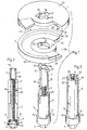
Figur 1 eine erste Ausführungsform eines Federnspanners in perspektivischer AnsichtFigur 2 einen Teil des Federnspanners der Fig. 1 in SchnittdarstellungFigur 3 eine andere Ausführung eines FührungsrohresFigur 4 den in Fig. 1 dargestellten Federnspanner in Anwendung bei einer Schraubenfeder in perspektivischer DarstellungFigur 5 den Federnspanner der Fig. 1 mit einer gespannten Feder- Figur 6 ein anderes Anwendungsbeispiel des in Fig. 1 dargestellten Federnspanners bei einer teilweise in einen sogenannten Dom ragenden Druckfeder eines Kraftfahrzeuges
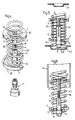
- Figur7 ein Gewinderohr und ein Führungsrohr mit Gewindespindel einer anderen Ausführungsform eines Federnspanners
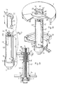
Figur 8 den kompletten Federnspanner mit den in Fig.7 dargestellten TeilenFigur 9 den in Fig. dargestellten Federnspanner im Schnitt
- Figure 1 shows a first embodiment of a spring tensioner in a perspective view
- Figure 2 shows a part of the spring tensioner of Fig. 1 in a sectional view
- Figure 3 shows another embodiment of a guide tube
- Figure 4 shows the spring tensioner shown in Fig. 1 in use with a coil spring in a perspective view
- 5 shows the spring tensioner of FIG. 1 with a tensioned spring
- FIG. 6 shows another application example of the spring tensioner shown in FIG. 1 in a compression spring of a motor vehicle that partially projects into a so-called dome
- Figure 7 shows a threaded tube and a guide tube with a threaded spindle of another embodiment of a spring tensioner
- Figure 8 shows the complete spring tensioner with the parts shown in Figure 7
- 9 shows the spring tensioner shown in FIG
Der in der Zeichnung dargestellte Federnspanner besteht im wesentlichen aus zwei Druckplatten 1 und 2, einem Gewinderohr 3, einer in das Gewinderohr einschraubbaren Gewindespindel 4 und aus einem Führungsrohr 5, in dem die Gewindespindel 4 mittels eines Axiallagers 6 drehbar gelagert ist. Das Gewinderohr 3 weist an seinem unteren Abschnitt ein Innengewinde 7 auf (Fig. 2), das sich etwa über ein Drittel der Gesamtlänge des Gewinderohres 3 erstreckt und in welches die Gewindespindel 4 einschraubbar ist. Durch das Axiallager 6 ist die an ihrem unteren Ende mit einem flanschartigen Stützring 8 und mit einem aus dem Führungsrohr 5 axial vorstehenden, mit einem Schlüsselprofil versehenen Spindelkopf 9 mittels eines in einer Ringnut 10 sitzenden Sicherungsringes 11 axial unverschiebbar im Führungsring 5 koaxial gelagert. In der Nähe des Spindelkopfes 9 ist das Führungsrohr 5 mit einer radial vorspringenden, ringschulterartigen Auflagefläche 12 versehen, die ihrerseits zwei sich diametral gegenüberliegende Axialvorsprünge 13 und 14 aufweisen,The spring tensioner shown in the drawing consists essentially of two
Bei den in den Fig. 1 und 2 dargestellten Ausführungsform des Federnspanners ist das Führungsrohr 5 etwa halb so lang wie die Gewindespindel 4, es ist jedoch mit zwei diametral angeordneten, zumindest annähernd in der gleichen Ebene wie die Gewindespindel 4 endenden Nutenfederstäben 15 und 16 versehen, welche in entsprechende Axialnuten 17 und 18 eingreifen, die in der Mantelfläche des Gewindeohres 3 angeordnet sind, wenn das Gewinderohr 3 mit der Gewindespindel 4, wie dargestellt, in Eingriff steht. Der Innendurchmesser des Führungsrohres 5 ist dabei so groß, daß das Gewinderohr 3 teleskopartig in das Führungsrohr 5 eintauchen kann. Dementsprechend sind die beiden Nutenfederstäbe 15 und 16 so gestaltet, daß sie in ihrer ganzen Länge gegenüber der Innenfläche des Führungsrohres 5 radial nach innen um die Nutentiefe der beiden Nuten 17 und 18 vorspringen. Durch diese Nut-Feder-Verbindung ist sichergestellt, daß sich das Gewinderohr 3 relativ zum Führungsrohr 5 nicht verdrehen kann, so lange das Gewinderohr 3 mit der Gewindespindel 4 bzw. so lange die Nutenfederstäbe 15 und 16 mit den Nuten 17 und 18 in Eingriff stehen. Am oberen Ende des Gewinderohres 3 sind zwei sich diametral gegenüberstehende Radialfinger 19 und 20 angeordnet. Während die Auflagefläche 12 des Führungsrohres 5 mit ihren beiden Axialvorsprüngen 13 und 14 zur Herstellung einer drehsicheren Zugverbindung zwischen der Druckplatte 2 und dem Führungsrohr 5 dient, sind die beiden Radialfinger 19 und 20 zur Herstellung einer verdrehsicheren Zugverbindung zwischen der Druckplatte 1 und dem Gewinderohr 3 vorgesehen. Die Druckplatte 2, die bei Gebrauch des Federnspanners auf der Auflagefläche 12 aufliegt und sich dann in Spindelkopfnähe befindet, weist eine Zentralbohrung 21 auf, deren Durchmesser geringfügig größer ist als der Aussendurchmesser des Führungsrohres 5 und kleiner als der Aussendurchmesser der Auflagefläche 12. Die Zentralbohrung 21 ist zudem mit zwei radialen, nutenförmigen Ausnehmungen 22 und 23 versehen, die zur formschlüssigen Aufnahme der beiden Axialvorsprünge 13 und 14 dienen. Ausserdem dienen diese Ausnehmungen 22 und 23 zum Durchstecken der Radialfinger 19 und 20 des Gewinderohres 3. Entsprechend sind die Querschnittsprofile der Ausnehmungen 22 und 23 sowie der Axialvorsprünge 13 und 14 und der Radialvorsprünge 19 und 20 aufeinander abgestimmt.In the embodiment of the spring tensioner shown in FIGS. 1 and 2, the
Die andere mit dem Gewinderohr 3 in drehfeste Zugverbindung zu bringende Druckplatte 1 weist ebenfalls eine Zentralbohrung 24 auf, die mit zwei in axialer Richtung durchgehend offenen, diametral zueinander angeordneten Ausnehmungen 22' und 23' versehen ist. Diese Ausnehmungen 22' und 23' dienen ebenfalls zum axialen Hindurchstecken der Radialfinger 19 und 20 des Gewinderohres 3. Sie haben deshalb die gleiche Breite und gleiche radiale Weite wie die Ausnehmungen 22 und 23 der Zentralbohrung 21 der Druckplatte 2, Auf der in der Zeichnung sichtbaren Aussenseite sind im Randbereich der Zentralbohrung 24 zwei um 90° versetzt zu den Ausnehmungen 22' und 23' angeordnete Vertiefungen 25 und 26 vorgesehen, in welche die Radialfinger 19 und 20 formschlüssig eingesetzt werden können, um zwischen dem Gewinderohr 3 und der Druckplatte 1 eine drehfeste Zugverbindung herzustellen, wenn wie das beispielsweise die Fig. 1 zeigt, der Durchmesser der Zentralbohrung 24 nur geringfügig größer ist als der Aussendurchmesser des Gewinderohres 3, also das Führungsrohr 5 nicht in die Zentralbohrung 24 eindringen kann, so wird der Spannhub dadurch begrenzt, daß die Spannplatte 1 auf der oberen Stirn-Ringfläche 27 des Führungsrohres 5 aufsitzt. Wenn man jedoch die Zentralbohrung 24 mit einem größeren Durchmesser versieht, so daß sie in der Lage ist auch das Führungsrohr 5 aufzunehmen und wenn man zudem, wie in Fig. 3 dargestellt ist, das Führungsrohr 5 noch mit Axialschlitzen versieht, in welche die beiden Radialfinger 19 und 20 axial eindringen können, so hat das Führungsrohr 5 auf die Spannhubbegrenzung keinen Einfluß.The
Die beiden Druckplatten 1 und 2 sind im wesentlichen gleich ausgebildet, wenn man von der dargestellten unterschiedlichen Gestaltung der Zentralbohrungen 21 und 24 und den Vertiefungen 25 und 26 der Druckplatte 1 absieht, wobei aber durchaus die Möglichkeit besteht, die Druckplatten auch diesbezüglich identisch auszubilden, wie nachstehend noch näher erläutert wird. Beide Druckplatten haben die Form einer tellerartigen kreisrunden Scheibe mit jeweils einem ringsegmentartigen, sich etwa über 70 bis 90° erstreckenden Ausschnitt 28, der zum Durchführen eines Federwindungsabschnittes dient. Ihre jeweils auf den voneinander abgekehrten Seiten angeordneten Aussenflächen 29 bzw. 30 sind glatt. Auf den einander zugekehrten Innenseiten sind jeweils innerhalb eines am äusseren Rand umlaufenden Ringbundes 31 bzw. 32 schraubenartig gewundene Ringflächen 33 bzw. 34 vorgesehen, die beim gezeigten Ausführungsbeispiel der Fig. 1 jeweils mit einem Reibbelag 35 bzw. 36 in Form eines aufgeklebten oder aufvulkanisierten Gummibandes versehen sind. Diese Reibbeläge 35 und 36 sollen dazu dienen, eine bessere Halterung der jeweiligen Federwindung, an welche die Platten angesetzt sind, in radialer Richtung zu gewährleisten. Anstelle eines Gummibandes kann als Reibbelag auch z. B. ein Schmirgelstreifen vorgesehen sein und anstelle eines Reibbelages könnten die Ringflächen 33 und 34 mit einer oder mehreren konzentrischen Rillen, die ebenfalls eine Zentrierung der ein- . gespannten Federwindungen bewirken können, versehen sein.The two
Die Handhabung und Anwendung eines solchen Federnspanners soll nun anhand der Fig. 4, 5 und 6 erläutert werden. Fig. 4 zeigt eine bereits aus einem Kraftfahrzeug ausgebaute oder noch nicht eingebaute Schraubenfeder 40 eines Kraftfahrzeuges, in welche der Federnspanner der Fig. 1 bereits spannbereit eingesetzt ist. Dabei erfolgte das Einsetzen in der Weise, daß zunächst die Druckplatten 1 und 2 jeweils separat in der dargestellten Weise zwischen zwei Windungsgänge der Schraubenfeder 40 von der Seite her eingesetzt wurden, bis sie eine zu den Federwindungen etwa konzentrische Lage eingenommen haben. Dann wurde von unten her das aus dem Gewinderohr 3, der Gewindespindel 4 und dem Führungsrohr 5 bestehende Spannaggregat in axialer Richtung zunächst durch die untere Druckplatte 2 und dann durch die obere Druckplatte 1 hindurchgesteckt wurde um die beiden Radialfinger 19 und 20 in die Vertiefungen 25 und 26 der oberen Druckplatte 1 zu setzen. Es ist dabei darauf zu achten, daß die Axialvorsprünge 13 und 14 in die Ausnehmungen 22 und 23 der unteren Druckplatte 2 zu sitzen kommen und der Rand der Zentralbohrung 21 auf der Auflagefläche 12 aufsitzt. Man kann von Hand oder mittels eines Schlagschraubers 41 die Gewindespindel 4 in Drehung versetzt werden, so daß sich eine Verkürzung des Plattenabstandes ergibt und dabei die zwischen den Druckplatten 1 und 2 befindlichen Federwindungen zusammengedrückt werden. Es ist dabei erkennbar, daß sich ausserhalb der beiden Druckplatten 1 und 2 noch eine oder mehrere Windungen der Schraubenfeder 40 befinden können, die zwar die Verkürzung der Gesamtfederlänge mitmachen, jedoch selbst nicht zusammengedrückt werden. Je nach der Anzahl der zwischen den Druckplatten 1 und 2 liegenden Federwindungen können diese maximal so weit zusammengepreßt werden, daß sie sich berühren. Dann kann diese Schraubenfeder 40 beispielsweise in der in Fig. 5 dargestellten Weise in einem Kraftfahrzeug zwischen einer unteren Stützpfanne 42 und einem oberen Stützteller 43 angebracht und durch entsprechendes Drehen der Gewindespindel entspannt werden, bis die ausserhalb der oberen Druckplatte 1 liegende Windung am Stützteller 43 anliegt und die beiden Druckplatten 1 und 2 keinem Federdruck mehr ausgesetzt sind. Dann wird durch weiteres Drehen der Gewindespindel 4 das Gewinderohr 3 so weit angehoben, daß die beiden Radialfinger 19 und 20 aus den Vertiefungen 25 und 26 der oberen Druckplatte 1 nach oben ausgehoben, das Führungsrohr 5 mit dem Gewinderohr 3 um 90° verdreht und nach unten durch beide Druckplatten 1 und 2 herausgezogen werden kann. Danach werden dann die beiden Druckplatten 1 und 2 seitlich aus der Feder herausgenommen. Um das Spannaggregat nach unten herausnehmen zu können, ist die Stützpfanne 42 mit einer Zentralöffnung 42' versehen. In Fig. 6 ist dargestellt, wie die Schraubenfeder 40 beispielsweise auch so eingesetzt werden kann, daß sie mit ihrem oberen Ende in einen im Fahrzeug vorhandenen Dom 44 hineinragt, wenn die Schraubenfeder 40 entspannt ist. Das Herauslösen des Führungsrohres 5 und des Gewinderohres 3 aus den beiden Druckplatten 1 und 2 erfolgt in der vorbeschriebenen Weise. Während dann die untere Druckplatte 2 einfach seitlich aus der Schraubenfeder 40 herausgezogen werden kann, ist es erforderlich, die obere Druckplatte den Windungen entlang nach unten zu drehen um sie dann, wenn sie den Dom 44 verlassen hat, ebenfalls seitlich herausnehmen zu können.The handling and use of such a spring tensioner will now be explained with reference to FIGS. 4, 5 and 6. FIG. 4 shows a
In Fig. 3 ist ein Führungsrohr 5' dargestellt, das gleich lang ist wie die Gewindespindel 4 und deren Nutenfederstäbe 15' und 16' vollständig in die Wandung integriert sind. Dieses Führungsrohr 5 läßt sich ohne weiteres mit dem Gewinderohr 3 der Fig. 1 und 2 kombinieren. Damit der maximale Arbeitshub durch die obere Stirnringfläche 27' nicht begrenzt wird, sind zwei um 90° zu den Nutenfederstäben 15' und 16' versetzt angeordnete, sich also auch diametral gegenüberliegende Axialschlitzte 45 und 46 vorgesehen, in welche die beiden Radialfinger 19 und 20 des Gewinderohres 3 eindringen können, welche ja auch jeweils um 90° zu den Axialnuten 17 und 18 angeordnet sind. Weil bei dieser Ausführungsform des Führungsrohres 5' die Nutenfederstäbe 15' und 16' über ihre ganze Länge in die Wandung integriert sind, weisen sie eine größere Stabilität gegen Verdrehen auf als die über die Länge des Führungsrohres 5 hinaus verlängerten Nutenführungsstäbe 15 und 16.In Fig. 3, a guide tube 5 'is shown, which is the same length as the threaded
In Verbindung mit den beiden Druckplatten 1 und 2 sowie mit dem Gewinderohr 3 läßt sich das in Fig. dargestellte Führungsrohr 5' mit der darin drehbar gelagerten Gewindespindel 4 in gleicher Weise handhaben und anwenden wie zuvor beschrieben.In connection with the two
Bei dem in den Fig.7, 8 und 9 dargestellten Federnspanner ist ein Führungsrohr 5/1 vorgesehen, das ebenso wie die Führungsrohre 5 und 5' mit einer Auflagefläche 12 und zwei Axialvorsprüngen 13 und 14 versehen ist und in welcher die Gewindespindel 4 in der gleichen Weise drehbar gelagert ist. Das Führungsrohr 5/1 ist gleich lang wie die Gewindespindel 4, d. h. ihre obere Stirnfläche 27' liegt zumindest annähernd in der gleichen Ebene wie die stirnseitige Endfläche der Gewindespindel 4. Statt zweier Nu. tenfederstäbe wie beim Ausführungsbeispiel der Fig. 1 oder zweier Nutensteine, die beim Führungsrohr 5' der Fig.3 vorgesehen sein könnten, weist das Führungsrohr 5/1 einen axialen Führungsschlitz 47 auf, der sich bis in die Nähe der Auflagefläche 12 erstreckt und der an der oberen Stirnringfläche 27' offen ist. Das Gewinderohr 3/1 ist an seinem unteren Ende mit einem Radialvorsprung 3' versehen, der in axialer Richtung fluchtend mit dem Radialfinger angeordnet ist und der dafür vorgesehen ist, im Führungsschlitz 47 des Führungsrohres 5/1 axial verschiebbar geführt zu werden und die drehfeste Verbindung zwischen dem Gewinderohr 3/1 und dem Führungsrohr 5/1 herzustellen. Der Innendurchmesser des Führungsrohres 5/1 und der Aussendurchmesser des Gewinderohres 3/1 sind so aufeinander abgestimmt, daß das Gewinderohr 3/1 teleskopartig in das Führungsrohr 5/1 eintauchen kann. Damit bei diesem Eintauchen des Gewinderohres 3/1 in das Führungsrohr 5/1 die beiden Radialfinger 19 und 20 nicht auf der oberen Stirnringfläche 27' aufsitzen und den Arbeitshub begrenzen, ist einerseits die fluchtende Anordnung zwischen dem Radialfinger 20 und dem Radialvorsprung 3' vorgesehen und andererseits für den Radialfinger 19 im Führungsrohr 5/1 ein zweiter oben offener Axialschlitz 48 diametral zum Führungsschlitz 47 angeordnet. Dabei ist die Länge 12 des Axialschlitzes 48 etwa um die Länge 11 des Gewinderohres 3/1 kürzer als die Länge 13 des Führungschlitzes 47, um die Verwindungsstabilität des Führungsrohres 5/1 nicht ungebührlich zu schwächen. Damit das Gewinderohr 3/1 auch dann vollständig in das Führungsrohr 5/1 eindringen kann, wenn es mit der Druckplatte 1' in der in Fig. dargestellten Weise verbunden ist, ist diese Druckplatte 1' mit einer Zentralbohrung 24' versehen, deren Durchmesser geringfügig größer ist als der Aussendurchmesser des Führungsrohres 5/1, so daß das Führungsrohr 5/1 in diese Zentralbohrung 24' eindringen kann. Die beiden Druckplatten 1' und 2', die im übrigen die gleiche Form aufweisen, wie die Druckplatten 1 und 2 des Ausführungsbeispieles der Fig. 1 und 2, weisen statt der Reibbeläge 35 und 36 jeweils konzentrische Führungsrillen 49 auf, in denen die Federwindungen, die mit den Druckplatten 1' und 2' unmittelbar in Berührung kommen, eine gute zentrierende radiale Führung erhalten, was für ein gleichmäßiges geradliniges Spannen der Schraubenfeder 40 wichtig ist.In the spring tensioner shown in FIGS. 7, 8 and 9, a
Bei dieser Ausführungsform und auch bei der Ausführungsform mit dem in Fig. dargestellten Führungsrohr 5' ist es möglich jeweils zwei völlig gleich geformte Druckplatten 1' und 2' zu verwenden, wobei die untere Druckplatte 2' entweder in der in Fig.8 dargestellten Weise auf der Auflagefläche 12 aufsitzend oder um 90° verdreht angeordnet sein kann, wobei dann die beiden Axialvorsprünge 13 und 14 in die ebenfalls vorhandenen Vertiefungen 25 und 26 eingreifen würden. In diesem Fall würde sich dann die untere Druckplatte 2' auf den Stirnflächen der Axialvorsprünge 13 und 14 und nicht auf der Auflagefläche 12 abstützen.In this embodiment and also in the embodiment with the guide tube 5 'shown in Fig. It is possible to use two completely identical pressure plates 1' and 2 ', the lower pressure plate 2' either in the manner shown in Fig.8 of the
Die Anwendung und Handhabung dieses in den Fig. 7, 8 und 9 dargestellten Federnspanners ist im wesentlichen genau gleich wie bei dem Federnspanner der Fig. 1 und 2.The application and handling of this spring tensioner shown in FIGS. 7, 8 and 9 is essentially exactly the same as for the spring tensioner of FIGS. 1 and 2.
Claims (13)
Priority Applications (1)
| Application Number | Priority Date | Filing Date | Title |
|---|---|---|---|
| AT84100103T ATE19984T1 (en) | 1983-02-09 | 1984-01-07 | SPRING COMPRESSOR. |
Applications Claiming Priority (2)
| Application Number | Priority Date | Filing Date | Title |
|---|---|---|---|
| DE3304321A DE3304321C2 (en) | 1983-02-09 | 1983-02-09 | Spring tensioner |
| DE3304321 | 1983-02-09 |
Publications (2)
| Publication Number | Publication Date |
|---|---|
| EP0115774A1 EP0115774A1 (en) | 1984-08-15 |
| EP0115774B1 true EP0115774B1 (en) | 1986-05-28 |
Family
ID=6190341
Family Applications (1)
| Application Number | Title | Priority Date | Filing Date |
|---|---|---|---|
| EP84100103A Expired EP0115774B1 (en) | 1983-02-09 | 1984-01-07 | Spring compressor |
Country Status (7)
| Country | Link |
|---|---|
| US (1) | US4527782A (en) |
| EP (1) | EP0115774B1 (en) |
| JP (1) | JPS59167308A (en) |
| AT (1) | ATE19984T1 (en) |
| AU (1) | AU564814B2 (en) |
| CA (1) | CA1215086A (en) |
| DE (1) | DE3304321C2 (en) |
Cited By (2)
| Publication number | Priority date | Publication date | Assignee | Title |
|---|---|---|---|---|
| DE10247643A1 (en) * | 2002-10-11 | 2004-04-22 | Audi Ag | Holder for axle springs e.g. helical springs, of motor vehicles has spring plates with central passage with slot-shaped aperture |
| DE10361597B3 (en) * | 2003-12-24 | 2005-06-30 | Klann-Spezial-Werkzeugbau-Gmbh | System for tensioning a coil spring |
Families Citing this family (19)
| Publication number | Priority date | Publication date | Assignee | Title |
|---|---|---|---|---|
| DE3733723A1 (en) * | 1986-10-10 | 1988-04-21 | Kleinbongartz & Kaiser Werkzeu | Spring clamp (spring vice, spring compressor) |
| DE3720018C2 (en) * | 1986-12-11 | 1988-09-29 | Horst Klann | SPRING TENSIONER |
| NL8700248A (en) * | 1987-02-02 | 1988-09-01 | Ir Gerrit Schmidt | SPRING PACKAGE FOR A VEHICLE AND METHOD FOR MOUNTING SUCH A SPRING PACKAGE. |
| DE8708476U1 (en) * | 1987-06-16 | 1987-08-06 | Klann, Horst, 7730 Villingen-Schwenningen | Spring tensioner |
| DE3823041C1 (en) * | 1988-07-07 | 1989-10-12 | Horst 7730 Villingen-Schwenningen De Klann | |
| FR2647045B1 (en) * | 1989-05-19 | 1994-04-08 | Mecanique Energetique | DEVICE FOR ASSEMBLING AND DISASSEMBLING HELICAL SPRINGS |
| DE4211176C2 (en) * | 1992-04-03 | 1998-07-23 | Porsche Ag | Bearing for a shock absorber of a motor vehicle |
| DE9400972U1 (en) * | 1994-01-21 | 1994-03-17 | Klann, Horst, 78052 Villingen-Schwenningen | Plastic pad for the gripper elements of a spring tensioner |
| DE19631524C1 (en) * | 1996-08-03 | 1997-11-27 | Angelika Weishaar | Spring clamp, especially for vehicle helical springs |
| DE20119267U1 (en) | 2001-11-27 | 2002-02-21 | Klann Tools Ltd., Oxfordshire | Eccentric pressure plates for spring tensioners |
| US20040169324A1 (en) * | 2003-02-28 | 2004-09-02 | Bottene Marlon V. | Strut spring seat |
| US20040169323A1 (en) * | 2003-02-28 | 2004-09-02 | Bottene Marlon V. | MacPherson strut spring coil mounts |
| DE202006010137U1 (en) * | 2006-06-28 | 2006-09-28 | Klann-Spezial-Werkzeugbau-Gmbh | Device aligning pressure plate of vehicle suspension coil spring tensioner, has head with radial lobes engaging enlargements of pressure plate penetration |
| US7510175B2 (en) * | 2007-01-29 | 2009-03-31 | Mei Hwa Technology Corp. | Assisting ejection device for hatch of hatchback |
| US8112856B2 (en) * | 2008-08-05 | 2012-02-14 | Yakita Metal Industry Co., Ltd. | Clamp of anti-vibration spring |
| JP6167705B2 (en) * | 2013-07-11 | 2017-07-26 | 株式会社Ihi | Catalyst support fixture |
| DE102021120678A1 (en) | 2021-08-09 | 2023-02-09 | GEDORE Holding GmbH | spring compressor |
| FR3139033B1 (en) * | 2022-08-30 | 2024-07-26 | Psa Automobiles Sa | Compression cup of a motor vehicle shock absorber |
| CN117300591B (en) * | 2023-06-02 | 2024-05-24 | 广州奥图弹簧有限公司 | Spring pipe-in equipment and spring thermal compression method |
Family Cites Families (9)
| Publication number | Priority date | Publication date | Assignee | Title |
|---|---|---|---|---|
| FR344191A (en) * | 1904-06-21 | 1904-10-26 | Julien Francois Mamet | Elastic rod to support the saddle or handlebars of bicycles, motorcycles, tricycles |
| GB916897A (en) * | 1961-08-24 | 1963-01-30 | Leonard Salvatore Suozzo | Floor type spring support |
| US3256594A (en) * | 1964-07-10 | 1966-06-21 | Eugene C Howard | Spring compressing tool |
| US3747895A (en) * | 1971-11-04 | 1973-07-24 | M Martin | Spring extender |
| GB1437455A (en) * | 1973-04-30 | 1976-05-26 | Girling Ltd | Spring compression tools |
| JPS5036200U (en) * | 1973-07-28 | 1975-04-16 | ||
| DE2703048A1 (en) * | 1977-01-26 | 1978-08-10 | Adolf Woitzik | Spring tensioner for car suspension - has central sleeve with threaded spindle and adjustable pressure plates which are removable |
| DE7800663U1 (en) * | 1978-01-11 | 1978-04-27 | Klann, Horst, 7730 Villingen | DEVICE FOR TENSIONING LARGE SCREW COMPRESSION SPRINGS |
| DE2813381C2 (en) * | 1978-03-28 | 1982-12-30 | Horst 7730 Villingen-Schwenningen Klann | Compression spring tensioner |
-
1983
- 1983-02-09 DE DE3304321A patent/DE3304321C2/en not_active Expired
-
1984
- 1984-01-07 AT AT84100103T patent/ATE19984T1/en active
- 1984-01-07 EP EP84100103A patent/EP0115774B1/en not_active Expired
- 1984-01-20 US US06/572,517 patent/US4527782A/en not_active Expired - Lifetime
- 1984-02-08 AU AU24263/84A patent/AU564814B2/en not_active Ceased
- 1984-02-08 CA CA000447053A patent/CA1215086A/en not_active Expired
- 1984-02-09 JP JP59020933A patent/JPS59167308A/en active Granted
Cited By (3)
| Publication number | Priority date | Publication date | Assignee | Title |
|---|---|---|---|---|
| DE10247643A1 (en) * | 2002-10-11 | 2004-04-22 | Audi Ag | Holder for axle springs e.g. helical springs, of motor vehicles has spring plates with central passage with slot-shaped aperture |
| DE10247643B4 (en) * | 2002-10-11 | 2004-09-23 | Audi Ag | Bracket for coil springs on motor vehicle axles |
| DE10361597B3 (en) * | 2003-12-24 | 2005-06-30 | Klann-Spezial-Werkzeugbau-Gmbh | System for tensioning a coil spring |
Also Published As
| Publication number | Publication date |
|---|---|
| US4527782A (en) | 1985-07-09 |
| JPS59167308A (en) | 1984-09-20 |
| ATE19984T1 (en) | 1986-06-15 |
| CA1215086A (en) | 1986-12-09 |
| DE3304321A1 (en) | 1984-08-16 |
| AU564814B2 (en) | 1987-08-27 |
| JPH059235B2 (en) | 1993-02-04 |
| DE3304321C2 (en) | 1985-02-21 |
| AU2426384A (en) | 1984-08-16 |
| EP0115774A1 (en) | 1984-08-15 |
Similar Documents
| Publication | Publication Date | Title |
|---|---|---|
| EP0115774B1 (en) | Spring compressor | |
| DE3507740C2 (en) | Self-locking, releasable locking nut | |
| EP0271782B1 (en) | Spring clamp | |
| DE2726452A1 (en) | DRIVE FOR A BLIND BLIND | |
| DE1928490B2 (en) | Screw clamp for paper stack - has tightening nut provided with split threaded collets for rapid engagement with pressure beam | |
| DE3739663C2 (en) | ||
| DE2700605A1 (en) | ANTI-ROTATION FOR A THREADED CONNECTION | |
| EP0275441B1 (en) | Clamping device | |
| WO2000014371A1 (en) | Screw-on hinge with blocked position | |
| EP0555633A1 (en) | Door handle fitting | |
| DE3038774A1 (en) | SCREW DRIVE WITH DOUBLE NUT | |
| EP4047219B1 (en) | Assembly unit with at least one mounting rail and at least one retaining clip | |
| DE3243948C2 (en) | ||
| DE2216588C3 (en) | Electrically powered can opener | |
| DE102019111237A1 (en) | Two-part screw nut with high pressing force | |
| DE3733723C2 (en) | ||
| DE29505752U1 (en) | Device for connecting plates by means of screwing | |
| DE2806417C2 (en) | Polygonal lock pin | |
| DE29702673U1 (en) | Spring tensioner for tensioning coil springs with two pressure plates | |
| DE4316808C2 (en) | Clamping piece for pipe elements | |
| DE2747152C3 (en) | Multi-turn switch | |
| DE8303510U1 (en) | SPRING TENSIONER | |
| DE1188378B (en) | Fastening device | |
| DE1502570C3 (en) | Grinding tool with drive spindle | |
| DE700295C (en) | Wood connection |
Legal Events
| Date | Code | Title | Description |
|---|---|---|---|
| PUAI | Public reference made under article 153(3) epc to a published international application that has entered the european phase |
Free format text: ORIGINAL CODE: 0009012 |
|
| AK | Designated contracting states |
Designated state(s): AT BE CH FR GB IT LI NL SE |
|
| 17P | Request for examination filed |
Effective date: 19840613 |
|
| GRAA | (expected) grant |
Free format text: ORIGINAL CODE: 0009210 |
|
| AK | Designated contracting states |
Kind code of ref document: B1 Designated state(s): AT BE CH FR GB IT LI NL SE |
|
| REF | Corresponds to: |
Ref document number: 19984 Country of ref document: AT Date of ref document: 19860615 Kind code of ref document: T |
|
| ET | Fr: translation filed | ||
| ITF | It: translation for a ep patent filed | ||
| PLBI | Opposition filed |
Free format text: ORIGINAL CODE: 0009260 |
|
| 26 | Opposition filed |
Opponent name: KLEINBONGARTZ & KAISER Effective date: 19870128 |
|
| NLR1 | Nl: opposition has been filed with the epo |
Opponent name: KLEINBONGARTZ & KAISER |
|
| PLBN | Opposition rejected |
Free format text: ORIGINAL CODE: 0009273 |
|
| STAA | Information on the status of an ep patent application or granted ep patent |
Free format text: STATUS: OPPOSITION REJECTED |
|
| 27O | Opposition rejected |
Effective date: 19900425 |
|
| NLR2 | Nl: decision of opposition | ||
| PGFP | Annual fee paid to national office [announced via postgrant information from national office to epo] |
Ref country code: BE Payment date: 19921127 Year of fee payment: 10 |
|
| PGFP | Annual fee paid to national office [announced via postgrant information from national office to epo] |
Ref country code: AT Payment date: 19921217 Year of fee payment: 10 |
|
| PGFP | Annual fee paid to national office [announced via postgrant information from national office to epo] |
Ref country code: CH Payment date: 19930119 Year of fee payment: 10 |
|
| ITTA | It: last paid annual fee | ||
| PGFP | Annual fee paid to national office [announced via postgrant information from national office to epo] |
Ref country code: NL Payment date: 19930131 Year of fee payment: 10 |
|
| PGFP | Annual fee paid to national office [announced via postgrant information from national office to epo] |
Ref country code: SE Payment date: 19931203 Year of fee payment: 11 |
|
| PG25 | Lapsed in a contracting state [announced via postgrant information from national office to epo] |
Ref country code: AT Effective date: 19940107 |
|
| PG25 | Lapsed in a contracting state [announced via postgrant information from national office to epo] |
Ref country code: LI Effective date: 19940131 Ref country code: CH Effective date: 19940131 Ref country code: BE Effective date: 19940131 |
|
| BERE | Be: lapsed |
Owner name: KLANN HORST Effective date: 19940131 |
|
| PG25 | Lapsed in a contracting state [announced via postgrant information from national office to epo] |
Ref country code: NL Effective date: 19940801 |
|
| NLV4 | Nl: lapsed or anulled due to non-payment of the annual fee | ||
| REG | Reference to a national code |
Ref country code: CH Ref legal event code: PL |
|
| PG25 | Lapsed in a contracting state [announced via postgrant information from national office to epo] |
Ref country code: SE Effective date: 19950108 |
|
| PGFP | Annual fee paid to national office [announced via postgrant information from national office to epo] |
Ref country code: FR Payment date: 19950125 Year of fee payment: 12 |
|
| EAL | Se: european patent in force in sweden |
Ref document number: 84100103.5 |
|
| EUG | Se: european patent has lapsed |
Ref document number: 84100103.5 |
|
| PG25 | Lapsed in a contracting state [announced via postgrant information from national office to epo] |
Ref country code: FR Effective date: 19960930 |
|
| REG | Reference to a national code |
Ref country code: FR Ref legal event code: ST |
|
| PGFP | Annual fee paid to national office [announced via postgrant information from national office to epo] |
Ref country code: GB Payment date: 19971223 Year of fee payment: 15 |
|
| PG25 | Lapsed in a contracting state [announced via postgrant information from national office to epo] |
Ref country code: GB Free format text: LAPSE BECAUSE OF NON-PAYMENT OF DUE FEES Effective date: 19990107 |
|
| GBPC | Gb: european patent ceased through non-payment of renewal fee |
Effective date: 19990107 |
|
| APAH | Appeal reference modified |
Free format text: ORIGINAL CODE: EPIDOSCREFNO |