DE102019111237A1 - Two-part screw nut with high pressing force - Google Patents
Two-part screw nut with high pressing force Download PDFInfo
- Publication number
- DE102019111237A1 DE102019111237A1 DE102019111237.0A DE102019111237A DE102019111237A1 DE 102019111237 A1 DE102019111237 A1 DE 102019111237A1 DE 102019111237 A DE102019111237 A DE 102019111237A DE 102019111237 A1 DE102019111237 A1 DE 102019111237A1
- Authority
- DE
- Germany
- Prior art keywords
- nut
- screw
- thread
- pressure
- screw nut
- Prior art date
- Legal status (The legal status is an assumption and is not a legal conclusion. Google has not performed a legal analysis and makes no representation as to the accuracy of the status listed.)
- Granted
Links
- 238000003825 pressing Methods 0.000 title description 6
- 230000000295 complement effect Effects 0.000 claims abstract description 12
- 238000006073 displacement reaction Methods 0.000 claims abstract description 12
- 239000000463 material Substances 0.000 description 9
- 230000000694 effects Effects 0.000 description 3
- 238000004519 manufacturing process Methods 0.000 description 3
- 238000007639 printing Methods 0.000 description 3
- 101100116570 Caenorhabditis elegans cup-2 gene Proteins 0.000 description 2
- 101100116572 Drosophila melanogaster Der-1 gene Proteins 0.000 description 2
- 230000005489 elastic deformation Effects 0.000 description 2
- 238000000034 method Methods 0.000 description 2
- 238000007493 shaping process Methods 0.000 description 2
- 238000004804 winding Methods 0.000 description 2
- BUHVIAUBTBOHAG-FOYDDCNASA-N (2r,3r,4s,5r)-2-[6-[[2-(3,5-dimethoxyphenyl)-2-(2-methylphenyl)ethyl]amino]purin-9-yl]-5-(hydroxymethyl)oxolane-3,4-diol Chemical compound COC1=CC(OC)=CC(C(CNC=2C=3N=CN(C=3N=CN=2)[C@H]2[C@@H]([C@H](O)[C@@H](CO)O2)O)C=2C(=CC=CC=2)C)=C1 BUHVIAUBTBOHAG-FOYDDCNASA-N 0.000 description 1
- 229910000831 Steel Inorganic materials 0.000 description 1
- 239000000654 additive Substances 0.000 description 1
- 230000000996 additive effect Effects 0.000 description 1
- 230000000903 blocking effect Effects 0.000 description 1
- 238000000748 compression moulding Methods 0.000 description 1
- 238000010276 construction Methods 0.000 description 1
- 239000003302 ferromagnetic material Substances 0.000 description 1
- 238000010079 rubber tapping Methods 0.000 description 1
- 239000010959 steel Substances 0.000 description 1
Images


Classifications
-
- F—MECHANICAL ENGINEERING; LIGHTING; HEATING; WEAPONS; BLASTING
- F16—ENGINEERING ELEMENTS AND UNITS; GENERAL MEASURES FOR PRODUCING AND MAINTAINING EFFECTIVE FUNCTIONING OF MACHINES OR INSTALLATIONS; THERMAL INSULATION IN GENERAL
- F16B—DEVICES FOR FASTENING OR SECURING CONSTRUCTIONAL ELEMENTS OR MACHINE PARTS TOGETHER, e.g. NAILS, BOLTS, CIRCLIPS, CLAMPS, CLIPS OR WEDGES; JOINTS OR JOINTING
- F16B37/00—Nuts or like thread-engaging members
- F16B37/08—Quickly-detachable or mountable nuts, e.g. consisting of two or more parts; Nuts movable along the bolt after tilting the nut
- F16B37/0807—Nuts engaged from the end of the bolt, e.g. axially slidable nuts
- F16B37/0821—Nuts engaged from the end of the bolt, e.g. axially slidable nuts in two halves pivotally connected
-
- F—MECHANICAL ENGINEERING; LIGHTING; HEATING; WEAPONS; BLASTING
- F16—ENGINEERING ELEMENTS AND UNITS; GENERAL MEASURES FOR PRODUCING AND MAINTAINING EFFECTIVE FUNCTIONING OF MACHINES OR INSTALLATIONS; THERMAL INSULATION IN GENERAL
- F16B—DEVICES FOR FASTENING OR SECURING CONSTRUCTIONAL ELEMENTS OR MACHINE PARTS TOGETHER, e.g. NAILS, BOLTS, CIRCLIPS, CLAMPS, CLIPS OR WEDGES; JOINTS OR JOINTING
- F16B31/00—Screwed connections specially modified in view of tensile load; Break-bolts
- F16B31/04—Screwed connections specially modified in view of tensile load; Break-bolts for maintaining a tensile load
-
- F—MECHANICAL ENGINEERING; LIGHTING; HEATING; WEAPONS; BLASTING
- F16—ENGINEERING ELEMENTS AND UNITS; GENERAL MEASURES FOR PRODUCING AND MAINTAINING EFFECTIVE FUNCTIONING OF MACHINES OR INSTALLATIONS; THERMAL INSULATION IN GENERAL
- F16B—DEVICES FOR FASTENING OR SECURING CONSTRUCTIONAL ELEMENTS OR MACHINE PARTS TOGETHER, e.g. NAILS, BOLTS, CIRCLIPS, CLAMPS, CLIPS OR WEDGES; JOINTS OR JOINTING
- F16B37/00—Nuts or like thread-engaging members
- F16B37/08—Quickly-detachable or mountable nuts, e.g. consisting of two or more parts; Nuts movable along the bolt after tilting the nut
- F16B37/0871—Quickly-detachable or mountable nuts, e.g. consisting of two or more parts; Nuts movable along the bolt after tilting the nut engaging the bolt laterally, i.e. without the need to engage the end of the bolt
- F16B37/0892—Quickly-detachable or mountable nuts, e.g. consisting of two or more parts; Nuts movable along the bolt after tilting the nut engaging the bolt laterally, i.e. without the need to engage the end of the bolt in two or more pieces, e.g. assemblies made by two C-shaped nuts mutually interlocked, or retained by an additional member
Abstract
Die Erfindung betrifft eine Schraubenmutter mit einem Innengewinde und zwei Mutterteilen (1, 2), wobei jedes der Mutterteile (1, 2) einen Abschnitt des Innengewindes aufweist, der in radialer Richtung auf ein Außengewinde (25) aufschiebbar ist, und wobei die Mutterteile (1, 2) miteinander zusammenwirkende Verbindungselemente aufweisen, welche eine relative Verschiebung der Mutterteile (1, 2) in einer radial zur Achse des Innengewindes verlaufenden Richtung bis in eine Verwendungsposition ermöglichen, in der das Innengewinde der Schraubenmutter das Außengewinde (25) mit geringem Spiel umgreift. Die Verbindungselemente weisen Führungsflächen (9-20) auf, die die Mutterteile (1, 2) der Schraubenmutter beim Verschieben in die Verwendungsposition in einer Rotationsbewegung um eine quer zur Achse des Innengewindes verlaufende Rotationsachse führen,wobei jedes Mutterteil (1, 2) mindestens einen ersten Verriegelungsarm (5,7) aufweist, der auf einer Seite eine Führungsfläche (9, 11) aufweist, welche die Rotationsbewegung beim Verschieben der Mutterteile (1, 2) bewirkt und gegen eine komplementäre Führungsfläche (10, 12) an einem zweiten Verriegelungsarm (6, 8) des anderen Mutterteils (1, 2) anliegt.Die Schraubenmutter weist mehrere Andrückgewinde (36-41) auf, die um das Innengewinde herum angeordnet sind und die Andrückschrauben (26-31) aufnehmen, welche in axialer Richtung aus einer ersten axialen Endfläche (21) der Schraubenmutter herausschraubbar sind und im Bereich einer zweiten axialen Endfläche (22) der Schraubenmutter eine Aufnahme (35) für ein Schraubwerkzeug aufweisen, wobei mindestens ein Andrückgewinde (36, 39) in dem ersten Verriegelungsarm (5, 7) angeordnet ist, der die erste axiale Endfläche (21) aufweist, und wobei der mit dem ersten Verriegelungsarm (5,7) zusammenwirkende zweite Verriegelungsarm (6,8) mit der zweiten axialen Endfläche (22) eine Aussparung (42,43) aufweist, welche von der Andrückschraube (29, 26) durchragt wird.The invention relates to a screw nut with an internal thread and two nut parts (1, 2), each of the nut parts (1, 2) having a section of the internal thread which can be pushed onto an external thread (25) in the radial direction, and wherein the nut parts ( 1, 2) have mutually interacting connecting elements which allow a relative displacement of the nut parts (1, 2) in a direction running radially to the axis of the internal thread up to a position of use in which the internal thread of the screw nut engages around the external thread (25) with little play . The connecting elements have guide surfaces (9-20) which guide the nut parts (1, 2) of the screw nut when moving into the position of use in a rotational movement about an axis of rotation running transversely to the axis of the internal thread, each nut part (1, 2) at least one first locking arm (5,7), which has a guide surface (9, 11) on one side, which causes the rotational movement when the nut parts (1, 2) are moved, and against a complementary guide surface (10, 12) on a second locking arm ( 6, 8) of the other nut part (1, 2). The screw nut has several pressure threads (36-41) which are arranged around the internal thread and which receive the pressure screws (26-31), which in the axial direction come from a first axial end face (21) of the screw nut can be unscrewed and in the region of a second axial end face (22) of the screw nut have a receptacle (35) for a screwing tool, wherein at least one pressure thread (36, 39) is arranged in the first locking arm (5, 7) which has the first axial end surface (21), and wherein the second locking arm (6,8) cooperating with the first locking arm (5,7) with the second axial end face (22) has a recess (42, 43) through which the pressure screw (29, 26) protrudes.
Description
Die Erfindung betrifft eine Schraubenmutter mit einem Innengewinde und zwei Mutterteilen gemäß dem Oberbegriff des Patentanspruchs 1.The invention relates to a screw nut with an internal thread and two nut parts according to the preamble of
Eine derartige zweiteilige Schraubenmutter ist bekannt aus dem europäischen Patent
An den zwei Mutterteilen der Schraubenmutter sind miteinander zusammenwirkende Verbindungselemente mit Führungsflächen angeordnet, welche in der Verwendungsposition der Mutterteile derart zusammenwirken, dass eine radiale Verschiebung der Mutterteile, die aus der Verwendungsposition heraus und von dem Außengewinde fort gerichtet ist, blockiert ist. Um in die blockierende Verwendungsposition zu gelangen, werden die Mutterteile der Schraubenmutter nicht nur in radialer Richtung verschoben, sondern um eine quer zur Achse des Innengewindes verlaufende Rotationsachse rotiert bzw. verschwenkt. Diese Rotationsbewegung ist nur bei gelöster Schraubverbindung möglich. Bei angezogener Schraubverbindung stützt sich die Schraubenmutter mit einer Anlagefläche oder mehreren Anlagepunkten auf einer gegenüberliegenden Stützfläche ab, die in axialer Richtung unverschiebbar mit dem Außengewinde verbunden ist. Mindestens ein Mutterteil weist mindestens einen Verriegelungsarm auf. Der Verriegelungsarm hat zwei Seiten, die in Bezug auf die Gewindeachsen in entgegengesetzte Richtungen orientiert sind. Diese Seiten können auch als Oberseite und Unterseite bezeichnet werden, wenn davon ausgegangen wird, dass die Gewindeachse von oben nach unten verläuft. Nur eine dieser zwei Seiten des Verriegelungsarms weist eine die Rotationsbewegung bewirkende Führungsfläche auf, welche gegen eine komplementäre und entgegen gesetzt orientierte Führungsfläche des anderen Mutterteils anliegt. Die andere Seite des Verriegelungsarms kann in der Praxis die Außenseite bzw. axiale Endfläche des Mutterteils (Oberseite oder Unterseite) bilden und sich gegen eine Stützfläche eines Bauteils abstützen, gegen die die Schraubenmutter gespannt wird.On the two nut parts of the screw nut interacting connecting elements with guide surfaces are arranged, which cooperate in the use position of the nut parts in such a way that a radial displacement of the nut parts, which is directed out of the use position and away from the external thread, is blocked. In order to get into the blocking position of use, the nut parts of the screw nut are not only displaced in the radial direction, but are rotated or pivoted about an axis of rotation running transversely to the axis of the internal thread. This rotational movement is only possible when the screw connection is loosened. When the screw connection is tightened, the screw nut is supported with a contact surface or several contact points on an opposing support surface which is connected to the external thread in such a way that it cannot be displaced in the axial direction. At least one nut part has at least one locking arm. The locking arm has two sides that are oriented in opposite directions with respect to the threaded axes. These sides can also be referred to as the top and bottom if the thread axis is assumed to run from top to bottom. Only one of these two sides of the locking arm has a guide surface which brings about the rotational movement and which rests against a complementary and oppositely oriented guide surface of the other nut part. The other side of the locking arm can in practice form the outside or axial end face of the nut part (top or bottom) and can be supported against a support surface of a component against which the screw nut is tensioned.
Der Verriegelungsarm mit der Führungsfläche am ersten Mutterteil sowie der damit zusammenwirkende Materialabschnitt des zweiten Mutterteils können große Materialstärken aufweisen. Es ist möglich, dass die Materialstärke dieser Materialabschnitte jeweils der Hälfte gesamten Dicke der Mutter entspricht. Hierdurch lässt sich eine hohe Stabilität und Belastbarkeit dieser Materialabschnitte und damit der Mutter insgesamt erzielen. Ferner kann sich die Führungsfläche des Verriegelungsarms sowie die damit zusammenwirkende Führungsfläche über die gesamte Länge der Mutter erstrecken. Hierdurch ergibt sich eine große tragende Fläche und daher eine hohe Belastbarkeit.The locking arm with the guide surface on the first nut part and the material section of the second nut part that interacts therewith can have great material thicknesses. It is possible that the material thickness of these material sections corresponds to half of the total thickness of the nut. This makes it possible to achieve a high level of stability and resilience of these material sections and thus of the nut as a whole. Furthermore, the guide surface of the locking arm and the guide surface interacting therewith can extend over the entire length of the nut. This results in a large load-bearing surface and therefore a high load capacity.
Wenn die Anlagefläche der Schraubenmutter, welche beim Aufschrauben auf ein vertikales Außengewinde mit unten liegender Stützfläche von ihrer Unterseite gebildet wird, sich im verschraubten Zustand gegen die Stützfläche abstützt wird, ist das Verschwenken der Mutterteile blockiert und die Mutter kann nur durch Losschrauben von dem Außengewinde der Schraube oder Gewindestange gelöst werden. Wenn dagegen die Schraubenmutter nach dem Losschrauben um einige Umdrehungen einen gewissen Abstand zur Stützfläche aufweist, ist das Rotieren oder Verschwenken der Mutterteile möglich, die anschließend voneinander in radialer Richtung des Gewindes getrennt werden können.If the contact surface of the screw nut, which is formed by its underside when screwing onto a vertical external thread with the support surface lying below, is supported against the support surface in the screwed state, the pivoting of the nut parts is blocked and the nut can only be unscrewed from the external thread Screw or threaded rod can be loosened. If, on the other hand, the screw nut has a certain distance from the support surface after unscrewing it by a few turns, the nut parts can be rotated or pivoted, which can then be separated from one another in the radial direction of the thread.
Es sei darauf hingewiesen, dass die quer zur Achse des Innengewindes verlaufende Rotationsachse nicht notwendigerweise rechtwinklig zur Achse des Innengewindes verlaufen muss. Sie kann auch schräg oder windschief in Bezug auf die Achse des Innengewindes verlaufen. In der Praxis wird die Rotationsachse aber meist in etwa radial zur Innengewindeachse liegen.It should be noted that the axis of rotation running transversely to the axis of the internal thread does not necessarily have to run at right angles to the axis of the internal thread. It can also run at an angle or skew with respect to the axis of the internal thread. In practice, however, the axis of rotation will mostly lie approximately radially to the internal thread axis.
Anders ausgedrückt, weist die Schraubenmutter einen oder mehrere Gewindegänge Abstand zur gegenüberliegenden Stützfläche auf, wenn die Schraubenmutter auf das Außengewinde aufgeschoben und aufgeschwenkt wird. Durch Verschrauben der Schraubenmutter um die der Anzahl der Gewindegänge entsprechende Umdrehungszahl stützt sich die Schraubenmutter gegen die gegenüberliegende Stützfläche ab, wodurch ein erneutes Verschwenken der Mutterteile der Schraubenmutter und ein Lösen der Mutterteile voneinander blockiert ist. Das Zusammenfügen der Mutterteile ist dadurch erleichtert, dass auf einer Seite des Verriegelungsarms eine die Rotationsbewegung der Mutterteile bewirkende Führungsfläche angeordnet ist. Die gegenüberliegende Seite des Verriegelungsarms, das heißt die in Bezug auf die Gewindeachse zur Führungsfläche entgegengesetzt orientierte Seite des Verriegelungsarms bildet eine Außenfläche der Schraubenmutter an deren Oberseite oder Unterseite und kann sich beim Festschrauben gegen eine Stützfläche abstützen. Da der Verriegelungsarm auf einer Seite mit einer gegenüberliegenden Stützfläche zur Erzielung der Rotationsbewegung zusammenwirkt, ist seine Dicke nicht kritisch und muss keine bestimmten Fertigungstoleranzen einhalten.In other words, the screw nut has one or more thread turns at a distance from the opposite support surface when the screw nut is pushed onto the external thread and pivoted open. By screwing the screw nut by the number of revolutions corresponding to the number of threads, the screw nut is supported against the opposing support surface, whereby a renewed pivoting of the nut parts of the screw nut and a loosening of the nut parts from one another is blocked. The assembly of the nut parts is facilitated by the fact that a guide surface which effects the rotational movement of the nut parts is arranged on one side of the locking arm. The opposite side of the locking arm, that is to say the side of the locking arm which is oriented in the opposite direction to the guide surface with respect to the thread axis, forms an outer surface of the screw nut on its top or bottom and can be supported against a support surface when it is screwed tight. Since the locking arm cooperates on one side with an opposing support surface in order to achieve the rotational movement, its thickness is not critical and does not have to adhere to any specific manufacturing tolerances.
Die Schwenkbewegung oder Rotationsbewegung der Mutterteile um eine Achse quer zur Achse des Innengewindes beim Aufbringen der Mutterteile auf das Außengewinde stellt somit sicher, dass die gegenläufige Bewegung bei festgeschraubten Mutterteilen gesperrt ist. Die aus den Mutterteilen gebildete Schraubenmutter ist dadurch unlösbar auf dem Außengewinde fixiert.The pivoting or rotational movement of the nut parts about an axis transverse to the axis of the internal thread when the nut parts are attached on the external thread ensures that the opposite movement is blocked when the nut parts are screwed tight. The screw nut formed from the nut parts is thus permanently fixed on the external thread.
Eine derartige Schraubenmutter hat gegenüber konventionellen Schraubenmuttern erhebliche Handhabungsvorteile. So muss nicht die gesamte Länge des Außengewindes durch Aufschrauben der Schraubenmutter überwunden werden. Die Schraubenmutter muss beim Aufbringen in ihre Verwendungsposition lediglich radial aufgeschoben und verschwenkt werden und anschließend um wenige Umdrehungen festgezogen werden. Es können auch beide Mutterteile der Schraubenmutter in einer teilweise zusammen geschobenen Stellung fixiert sein, in der sie über das Außengewinde bis zur Wunschposition geschoben werden. Erst hier werden die Mutterteile gegeneinander in die Verwendungsposition gedrückt und anschließend fest mit dem Außengewinde verschraubt.A screw nut of this type has considerable handling advantages over conventional screw nuts. This means that the entire length of the external thread does not have to be overcome by unscrewing the screw nut. The screw nut only needs to be pushed on and pivoted radially when it is put into its position of use and then tightened by a few turns. Both nut parts of the nut can also be fixed in a partially pushed together position in which they are pushed over the external thread to the desired position. Only here are the nut parts pressed against each other into the position of use and then screwed tightly to the external thread.
Auch ist es möglich, eine zweiteilige Schraubenmutter an einem Außengewinde ohne freies Ende anzubringen. So kann die Schraubenmutter beispielsweise auf einen Gewindeabschnitt, der zu beiden Seiten von dickeren Stangenabschnitten ohne Gewinde begrenzt ist, aufgebracht werden. Die zweiteilige Schraubenmutter ermöglicht folglich außergewöhnliche Verbindungsarten, bei leichter Handhabung und kostengünstiger Herstellung.It is also possible to attach a two-part screw nut to an external thread without a free end. For example, the screw nut can be applied to a threaded section which is delimited on both sides by thicker rod sections without a thread. The two-part screw nut consequently enables unusual types of connection with easy handling and inexpensive production.
In der Praxis umfassen die Verbindungselemente der Mutterteile gegeneinander anliegende und die Rotation bewirkende Führungsflächen, die um einen Winkel zur radial zur Achse des Innengewindes verlaufenden Ebene geneigt sind. Dieser Winkel der Führungsflächen zur radialen Ebene des Innengewindes bewirkt, dass die Mutterteile der Schraubenmuttern nicht einfach radial gegeneinander verschoben, sondern zusätzlich um eine Achse im Wesentlichen in einer radialen Ebene des Innengewindes verschwenkt werden müssen.In practice, the connecting elements of the nut parts comprise guide surfaces which lie against one another and cause the rotation and are inclined at an angle to the plane extending radially to the axis of the internal thread. This angle of the guide surfaces to the radial plane of the internal thread has the effect that the nut parts of the screw nuts do not simply have to be displaced radially relative to one another, but also have to be pivoted about an axis essentially in a radial plane of the internal thread.
Die Führungsflächen sind in der Praxis vorzugsweise um einen Winkel von weniger als 20° zur radialen Ebene des Innengewindes geneigt. Hierdurch ist die zur Verbindung der Mutterteile erforderliche Schwenkbewegung nicht übermäßig groß und es wird eine Kollision der Konturen der Gewindeabschnitte der Mutterteile mit dem Außengewinde während der Schwenkbewegung vermieden. Sollten größere Neigungen gewünscht sein, müssten die kollidierenden Konturen der Gewindeabschnitte abgetragen werden. Die Führungsflächen können aber auch eine variable Neigung zur radialen Ebene aufweisen und beispielsweise zylinderartig gewölbt oder wendelförmig gewunden sein.In practice, the guide surfaces are preferably inclined at an angle of less than 20 ° to the radial plane of the internal thread. As a result, the pivoting movement required to connect the nut parts is not excessively large and a collision of the contours of the threaded sections of the nut parts with the external thread during the pivoting movement is avoided. If greater inclinations are required, the colliding contours of the thread sections would have to be removed. The guide surfaces can, however, also have a variable inclination to the radial plane and, for example, can be arched in the manner of a cylinder or wound in a helical manner.
Zur Erzielung der Schwenkbewegung können die Führungsflächen auf verschiedene Weisen angeordnet sein. Bei einer Schraubenmutter, bei der die Innengewindeabschnitte der zwei Mutterteile entlang einer sich in Richtung der Gewindeachse erstreckenden Teilungsebene getrennt sind, kann jedes Mutterteil der Schraubenmutter zwei Führungsflächen aufweisen, die zu beiden Seiten einer rechtwinklig zur Teilungsebene verlaufenden Mittelebene angeordnet sind. Wenn man die Richtung, in der sich die Führungsflächen erstrecken als Längsrichtung bezeichnet, bildet die Mittelebene die mittlere Längsebene, wobei die zwei Führungsflächen zu beiden Seiten dieser Mittelebene verlaufen. Ferner können die zwei Führungsflächen eines Mutterteils in entgegengesetzte Richtungen in Bezug auf die Gewindeachse orientiert sein. Wenn man annimmt, dass die Gewindeachse von oben nach unten verläuft, weist also die Flächennormale der ersten Führungsfläche eines Mutterteils nach oben und die Flächennormale der zweiten Führungsfläche des gleichen Mutterteils nach unten. Das komplementäre Mutterteil ist entsprechend ausgebildet. Zumindest ein Mutterteil der Führungsflächen ist an den Verriegelungsarmen angeordnet. Diese Ausbildung der schrägen Führungsflächen kann bei geeignetem Führungsflächenverlauf zu der Schwenkbewegung führen. Zum Beispiel können die Führungsflächen auf einer um eine in der Mittelebene liegende radiale Achse gewundene Wendelfläche liegen, die eine Schraubbewegung beim Zusammenschieben der zwei Mutterteile vorgibt. Die zwei Führungsflächen können auch auf einer Zylindermantelfläche liegen, deren Zylinderachse in der Teilungsebene liegt. In diesem Fall werden die Mutterteile beim zusammenschieben um die Zylinderachse zueinander verschwenkt.To achieve the pivoting movement, the guide surfaces can be arranged in various ways. In the case of a screw nut in which the internally threaded sections of the two nut parts are separated along a parting plane extending in the direction of the thread axis, each nut part of the screw nut can have two guide surfaces which are arranged on both sides of a center plane running at right angles to the parting plane. If the direction in which the guide surfaces extend is referred to as the longitudinal direction, the central plane forms the central longitudinal plane, the two guide surfaces running on both sides of this central plane. Furthermore, the two guide surfaces of a nut part can be oriented in opposite directions with respect to the thread axis. If one assumes that the thread axis runs from top to bottom, the surface normal of the first guide surface of a nut part points upwards and the surface normal of the second guide surface of the same nut part points downwards. The complementary nut part is designed accordingly. At least one nut part of the guide surfaces is arranged on the locking arms. This design of the inclined guide surfaces can lead to the pivoting movement given a suitable guide surface course. For example, the guide surfaces can lie on a helical surface which is wound around a radial axis located in the center plane and which defines a screwing movement when the two nut parts are pushed together. The two guide surfaces can also lie on a cylinder jacket surface, the cylinder axis of which lies in the dividing plane. In this case, the nut parts are pivoted to each other when they are pushed together about the cylinder axis.
Alternativ kann eine Schraubenmutter aus zwei Mutterteilen, deren Innengewindeabschnitte entlang einer sich in Richtung der Gewindeachse erstreckenden Teilungsebene getrennt sind, ebene Führungsflächen aufweisen, die nicht gewölbte oder gewunden sind. Um die Schwenkbewegung hervorzurufen, kann jedes Mutterteil der Schraubenmutter zwei Führungsflächen auf beiden Seiten der Teilungsebene aufweisen. Diese Führungsflächen sind auf der ersten Seite der Teilungsebene in entgegengesetzte Richtungen in Bezug auf die Gewindeachse orientiert, als die auf der zweiten Seite der Teilungsebene. Mit anderen Worten weisen die Führungsflächen eines Mutterteils auf der ersten Seite der Teilungsebene nach oben und auf der zweiten Seite der Teilungsebene nach unten. Ferner sind die Führungsflächen auf der ersten Seite der Teilungsebene in die entgegengesetzte Richtung zur radialen Ebene des Gewindes geneigt als die auf der zweiten Seite der Teilungsebene. Mit anderen Worten verlaufen die Ebenen, in denen die Führungsflächen liegen, wie ein Spitzdach, dessen Giebel auf der Gewindeachse liegt. So können die Mutterteile ineinander geschoben werden, wobei die Achsen der Innengewindeabschnitte der Mutterteile leicht zueinander verschwenkt sind. In dem letzten Abschnitt der Verschiebebewegung werden die Mutterteile in die Verwendungsposition geschwenkt, und zwar um eine radial zur Gewindeachse verlaufende Schwenkachse, die in der Teilungsebene liegt. In der Verwendungsposition liegen die Achsen der Innengewindeabschnitte der zwei Mutterteile im Wesentlichen aufeinander und das aus den zwei Abschnitten bestehende Innengewinde umgreift ein Außengewinde mit entsprechenden Maßen im Wesentlichen spielfrei. Dann kann die so gebildete Schraubenmutter festgeschraubt werden.Alternatively, a screw nut composed of two nut parts, the internal thread sections of which are separated along a dividing plane extending in the direction of the thread axis, can have flat guide surfaces that are not curved or twisted. To bring about the pivoting movement, each nut part of the screw nut can have two guide surfaces on both sides of the dividing plane. These guide surfaces are oriented on the first side of the parting plane in opposite directions with respect to the thread axis than those on the second side of the parting plane. In other words, the guide surfaces of a nut part point upwards on the first side of the dividing plane and downward on the second side of the dividing plane. Furthermore, the guide surfaces on the first side of the dividing plane are inclined in the opposite direction to the radial plane of the thread than those on the second side of the dividing plane. In other words, the planes in which the guide surfaces are located run like a pointed roof whose gable lies on the thread axis. So can the mother parts are pushed into one another, the axes of the internally threaded sections of the nut parts being pivoted slightly towards one another. In the last section of the displacement movement, the nut parts are pivoted into the position of use, specifically about a pivot axis extending radially to the thread axis and lying in the dividing plane. In the position of use, the axes of the internal thread sections of the two nut parts lie essentially on top of one another and the internal thread consisting of the two sections encompasses an external thread with corresponding dimensions essentially without play. Then the screw nut formed in this way can be screwed tight.
Wie erwähnt, können die Führungsflächen eine Wölbung in Form eines Zylindermantelabschnitts aufweisen. Die Führungsfläche am ersten Mutterteil ist dabei konvex geformt, und die hiermit zusammenwirkende Führungsfläche am zweiten Mutterteil ist konkav gemäß der gleichen Zylindermantelfläche geformt. So kann durch die Führungsfläche die Annäherungsbewegung der zwei Mutterteile über eine längere Bewegungsbahn entlang der genannten Zylindermantelfläche geführt werden.As mentioned, the guide surfaces can have a curvature in the form of a cylinder jacket section. The guide surface on the first nut part is convexly shaped, and the guide surface on the second nut part that interacts with it is shaped concave in accordance with the same cylinder jacket surface. Thus, the approach movement of the two nut parts can be guided over a longer movement path along the mentioned cylinder jacket surface by the guide surface.
In der Praxis kann die Achse des Innengewindes mit einem Radius des Zylinders, auf dessen Mantelfläche die Führungsflächen verlaufen, zusammenfallen. Auch kann die Teilung der Mutterteile in einer den Zylinder diametral schneidenden Ebene liegen. Die Rotation der Mutterteile bei der Bewegung in die Verwendungsposition erfolgt dann durch Verschieben der zylindermantelförmigen Führungsflächen zueinander im Wesentlichen um die in der Teilungsebene der Mutterteile liegende Achse des Zylindermantels.In practice, the axis of the internal thread can coincide with a radius of the cylinder on whose outer surface the guide surfaces run. The division of the nut parts can also lie in a plane which diametrically intersects the cylinder. The rotation of the nut parts during the movement into the use position then takes place by shifting the cylinder jacket-shaped guide surfaces relative to one another essentially around the axis of the cylinder jacket lying in the dividing plane of the nut parts.
Wie ebenfalls weiter oben erwähnt, können in einer weiteren praktischen Ausführungsform die Führungsflächen auf einer gewundenen Fläche liegen. Die Windung verläuft zum Beispiel um eine Achse, die rechtwinklig zur Ebene der Teilung der Mutter und radial zur Achse des Innengewindes verläuft und die Gewindeachse etwa in der Mitte des Innengewindes schneidet. In diesem Fall werden die Mutterteile beim Zusammenfügen nicht um eine in der Teilungsebene liegende Achse gedreht sondern um die senkrecht zur Teilungsebene der Mutter verlaufende Achse entlang einer Schraubenbewegung gedreht.As also mentioned above, in a further practical embodiment the guide surfaces can lie on a winding surface. The turn runs around an axis, for example, which runs at right angles to the plane of the division of the nut and radially to the axis of the internal thread and intersects the thread axis approximately in the middle of the internal thread. In this case, the nut parts are not rotated about an axis lying in the parting plane when they are joined, but rather rotated about the axis running perpendicular to the parting plane of the nut along a screw movement.
In der Praxis kann das Material der Schraubenmutter, meist Stahl aber je nach Anwendung auch Kunststoff, elastisch verformbar sein. Die Form zweier gegeneinander anliegender Führungsflächen der Mutterteile kann geringfügig voneinander abweichen. Die Flächen können leicht unterschiedlich gewölbt oder zueinander geneigt sein. Beide Merkmale führen dazu, dass bei Erhöhung des in Richtung der Achse des Innengewindes wirkenden Drucks durch Festschrauben der Muttern eine gewisse Verformung der Mutterteile erfolgt, bis die Führungsflächen flächig gegeneinander anliegen. Die Führungsflächen der Schraubenmutterteile übernehmen dabei die Funktion einer Unterlegscheibe oder Federscheibe und sichern zusätzlich die Schraubverbindung gegen Lösen aufgrund dynamischer Lastwechsel. Gleiches gilt, wenn die Unterseite der Mutterteile nur mit einem oder zwei Anlagepunkten auf der darunterliegenden Stützfläche aufliegt. Die Stützfläche ist die in axialer Richtung zum Außengewinde fixierte Fläche, gegen die sich die Schraubenmutter beim Festschrauben abstützt. Wenn diese Abstützung nur durch ein oder zwei Anlagepunkte pro Mutterteil erfolgt, wird beim Festschrauben ein Drehmoment erzeugt, das die Mutterteile elastisch ein wenig verformt und dabei verkantet. Die Mutter steht also wie bei Verwendung einer Unterlegscheibe unter elastischer Spannung, welche bei einer dynamischen Belastung der Verschraubung dafür sorgt, dass die Verschraubung aufgrund der Spannung selbsthemmend blockiert ist.In practice, the material of the screw nut, mostly steel but also plastic, depending on the application, can be elastically deformable. The shape of two mutually adjacent guide surfaces of the nut parts can differ slightly from one another. The surfaces can be curved slightly differently or inclined to one another. Both features mean that when the pressure acting in the direction of the axis of the internal thread is increased by tightening the nuts, a certain deformation of the nut parts takes place until the guide surfaces lie flat against one another. The guide surfaces of the screw nut parts take on the function of a washer or spring washer and also secure the screw connection against loosening due to dynamic load changes. The same applies if the underside of the nut parts rests with only one or two contact points on the support surface below. The support surface is the surface which is fixed in the axial direction to the external thread and against which the screw nut is supported when it is tightened. If this support is only provided by one or two contact points per nut part, a torque is generated when tightening, which elastically deforms the nut parts a little and thereby tilts them. The nut is therefore under elastic tension, as when a washer is used, which ensures that the screw connection is self-lockingly blocked due to the tension when the screw connection is dynamically loaded.
Zusätzlich können die Verbindungselemente der Mutterteile gegeneinander anliegende Führungsflächen aufweisen, die in einer sich parallel zur Achse des Innengewindes erstreckenden Ebene liegen. Diese sich parallel zur Achse des Innengewindes erstreckende Ebene definiert vorzugsweise die Richtung der radialen Verschiebung der zwei Schraubenmutterteile zueinander. Die zusätzlichen Führungsflächen bewirken also die Führung der Mutterteile in radialer Richtung des Gewindes, nicht aber die Rotationsbewegung. Ferner bilden zusätzliche Führungsflächen in einer axialen Ebene (auch vertikale Ebene genannt) die in der Verwendungsposition wirksamen Anschläge für die Verschiebung der Mutter. Diese zusätzlichen Führungsflächen bewirken wie gesagt kein Verschwenken der Schraubenmutterteile zum Erreichen der Verwendungsposition und wirken folglich auch nicht bei der Verriegelung der Schraubenmutterteile aneinander mit.In addition, the connecting elements of the nut parts can have mutually adjacent guide surfaces which lie in a plane extending parallel to the axis of the internal thread. This plane, which extends parallel to the axis of the internal thread, preferably defines the direction of the radial displacement of the two screw nut parts with respect to one another. The additional guide surfaces thus guide the nut parts in the radial direction of the thread, but not the rotational movement. Furthermore, additional guide surfaces in an axial plane (also called a vertical plane) form the stops which are effective in the position of use for the displacement of the nut. As mentioned, these additional guide surfaces do not cause the screw nut parts to pivot in order to reach the position of use and consequently do not cooperate in locking the screw nut parts to one another.
Wie erwähnt, bewirken die Verbindungselemente, welche ein Verschwenken der Schraubenmutterteile zum Erreichen ihrer Verwendungsposition notwendig machen, dass die Schraubenmutter beim Festschrauben an diesem Verschwenken dadurch gehindert ist, dass sich ihre Anlagefläche gegen eine mit dem Außengewinde verbundene Stützfläche abstützt. Dabei muss die Anlagefläche der Schraubenmutter nicht vollflächig ausgebildet sein. Es ist ausreichend, wenn jedes Mutterteil der Schraubenmutter mindestens einen, vorzugsweise zwei oder drei Anlagepunkte aufweist, die beim Festschrauben gegen die mit dem Außengewinde in axialer Richtung fest verbundene Stützfläche anliegen. Die Anlagefläche wird von der Seite des Verriegelungsarms gebildet, die der die Rotation bewirkenden Führungsfläche gegenüber liegt.As mentioned, the connecting elements, which require the screw nut parts to pivot in order to reach their position of use, have the effect that the screw nut is prevented from pivoting when it is tightened in that its contact surface is supported against a support surface connected to the external thread. The contact surface of the screw nut does not have to be designed over the entire surface. It is sufficient if each nut part of the screw nut has at least one, preferably two or three contact points which, when screwed tight, rest against the support surface firmly connected to the external thread in the axial direction. The contact surface is formed by the side of the locking arm which is opposite the guide surface causing the rotation.
Die Anlagefläche jedes Mutterteils der Schraubenmutter kann an einem Rand eine Schrägfläche aufweisen, welche den Winkel der Schwenkbewegung des Schraubenmutterteils definiert. Hierzu weist die Schrägfläche zur Anlagefläche einen Winkel auf, der dem Rotationswinkel des entsprechenden Schraubenmutterteils beim Bewegen dieses Mutterteils in seine Verwendungsposition entspricht. Mit anderen Worten können die zwei Schraubenmutterteile durch einen Druck auf ihren Rand um einen Winkel verschwenkt werden, der dem Schwenkwinkel aus der Montageposition in die Verwendungsposition entspricht. In diesem verschwenkten Zustand können die Schraubenmutterteile durch die Stützfläche ein wenig ineinander geschoben werden. Im letzten Abschnitt der Bewegung werden die Schraubenmutterteile in ihre Verwendungsposition geschwenkt und anschließend festgeschraubt, wobei sie aufgrund der Abstützung der Anlagefläche der Schraubenmutter gegen die Stützfläche arretiert werden. The contact surface of each nut part of the screw nut can have an inclined surface on one edge which defines the angle of the pivoting movement of the screw nut part. For this purpose, the inclined surface has an angle to the contact surface which corresponds to the angle of rotation of the corresponding screw nut part when this nut part is moved into its position of use. In other words, the two screw nut parts can be pivoted by a pressure on their edge by an angle which corresponds to the pivot angle from the mounting position into the position of use. In this pivoted state, the screw nut parts can be pushed into one another a little by the support surface. In the last section of the movement, the nut parts are pivoted into their position of use and then screwed tight, whereby they are locked due to the support of the contact surface of the nut against the support surface.
Ähnlich kann eine Schraubenmutter mit punktförmiger Anlage ausgebildet werden. Ein Anlagepunkt eines Schraubenmutterteils sollte mit wenigstens zwei weiteren Punkten im Randbereich des Schraubenmutterteils eine Schrägfläche definieren, deren Winkel dem Rotationswinkel entspricht, um den das Mutterteil bei der Montage gedreht wird. Wiederum kann durch Drücken auf den Randbereich ein Verschwenken des Schraubenmutterteils in die Montageposition erfolgen. In dieser Position kann das Schraubenmutterteil um ein gewisses Maß in das komplementäre Schraubenmutterteil geschoben werden. Anschließend erfolgt die manuelle Schwenkbewegung, wobei die Gewindeabschnitte beider Schraubenmutterteile sich um das Außengewinde legen und die Verwendungsposition erreicht wird.Similarly, a screw nut can be designed with a point-like contact. A contact point of a screw nut part should define an inclined surface with at least two further points in the edge region of the screw nut part, the angle of which corresponds to the angle of rotation by which the nut part is rotated during assembly. Again, by pressing on the edge area, the screw nut part can be pivoted into the assembly position. In this position, the screw nut part can be pushed into the complementary screw nut part to a certain extent. The manual pivoting movement then takes place, whereby the thread sections of both screw nut parts wrap around the external thread and the position of use is reached.
In der Praxis kann in mindestens einem Endbereich des Innengewindeabschnitts mindestens eines der Mutterteile die Gewindegänge abgetragen sein, um die Rotation der Mutterteile bei der Schwenkbewegung in die Verwendungsposition zu ermöglichen. Je nach gewählter Bewegungsbahn der Relativbewegung der Mutterteile zueinander vermeidet ein Abtragen der Gewindegänge ein Blockieren der Schließbewegung. Dabei können die Innengewindeabschnitte während der Schwenkbewegung um ein geringes Maß gegen das Außengewinde anschlagen, so dass bei der Schließbewegung in die Verwendungsposition eine elastische Verformung der Mutterteile erforderlich ist. Hierdurch schnappen die Mutterteile um das Außengewinde und sind nur durch einen erhöhten Kraftaufwand, der die genannte elastische Verformung hervorruft wieder von dem Außengewinde lösbar.In practice, at least one of the nut parts can have the threads removed in at least one end region of the internally threaded section in order to enable the nut parts to rotate during the pivoting movement into the position of use. Depending on the selected movement path of the relative movement of the nut parts to one another, removing the threads prevents the closing movement from being blocked. The internal thread sections can strike against the external thread by a small amount during the pivoting movement, so that elastic deformation of the nut parts is required during the closing movement into the position of use. As a result, the nut parts snap around the external thread and can only be released from the external thread again by an increased expenditure of force, which causes the elastic deformation mentioned.
Die zweiteilige Schraubenmutter kann selbstverständlich auch ein selbstschneidendes Gewinde aufweisen. Dabei kann die Abtragung im Bereich des Gewindes so gewählt werden kann, dass das Gewinde wie ein Gewindeschneider die Gewindegänge des Außengewindes schneidet. Damit könnte die Schraubenmutter noch besser an nachgiebigen Materialien ohne Gewinde, wie Kunststoffstangen oder kunststoffummantelten Kabeln, zum Beispiel als Zugentlastung bei Stromkabeln eingesetzt werden.The two-part screw nut can of course also have a self-tapping thread. The removal in the area of the thread can be selected so that the thread cuts the threads of the external thread like a thread cutter. The screw nut could thus be used even better on flexible materials without threads, such as plastic rods or plastic-coated cables, for example as a strain relief for power cables.
Durch besondere Ausgestaltung der Schraubenmutter können die zwei Mutterteile der Schraubenmutter identisch sein. Dies ist beispielsweise bei einem zweigängigen Gewinde ohne weiteres möglich, wenn Mutterteile rotationssymmetrisch, das heißt bei Drehung um 180° identisch zueinander, in Bezug auf die Gewindeachse oder eine in der Mutterteilungsebene und radial zur Gewindeachse verlaufende Symmetrieachse sind. Bei einem üblichen eingängigen Gewinde können die identischen Schraubenmutterteile rotationssymmetrisch in Bezug auf eine in der Mutterteilungsebene liegende und radial zur Gewindeachse verlaufende Symmetrieachse sein. Die Mutterteile weisen dabei vorzugsweise eine nach oben gerichtete und eine nach unten gerichtete Schrägfläche auf, die an zwei rechtwinklig zur Mutterteilungsebene verlaufenden Verriegelungsarmen angeordnet sind, welche als Verbindungselemente wirken. Diese Schrägflächen legen sich beim Verbinden auf die gegenüberliegenden Schrägflächen des komplementären Mutterteils. Die Mutterteile werden beim Verbinden auf einander zu verschoben und schraubenartig ineinander gedreht.Due to the special design of the screw nut, the two nut parts of the screw nut can be identical. This is easily possible with a double thread, for example, if nut parts are rotationally symmetrical, i.e. identical to one another when rotated by 180 °, with respect to the thread axis or an axis of symmetry running in the nut division plane and radially to the thread axis. In the case of a customary single-start thread, the identical screw nut parts can be rotationally symmetrical with respect to an axis of symmetry lying in the nut division plane and extending radially to the thread axis. The nut parts preferably have an upwardly directed and a downwardly directed inclined surface, which are arranged on two locking arms which run at right angles to the plane of the nut division and which act as connecting elements. When connecting, these inclined surfaces lie on the opposite inclined surfaces of the complementary nut part. The nut parts are moved towards each other during connection and screwed into each other.
Eine Schraubenmutter, bestehend aus zwei identischen Mutterteilen, hat den Vorteil, dass sie in hoher Stückzahl sehr kostengünstig herstellbar ist. Insbesondere kann jedes Mutterteil der Schraubenmutter in einem Formpressvorgang hergestellt sein. Außerdem kann der Benutzer beliebige Mutterteile miteinander verbinden und muss nicht zwei zueinander passende Mutterteile heraussuchen.A screw nut, consisting of two identical nut parts, has the advantage that it can be produced very cost-effectively in large numbers. In particular, each nut part of the screw nut can be produced in a compression molding process. In addition, the user can connect any nut parts to one another and does not have to search for two nut parts that fit together.
Bei Muttern mit eingängigem Innengewinde, die äußerlich symmetrische Formen haben mögen, deren Gewindegänge aber nicht symmetrisch sind, sowie bei unsymmetrischen Mutterteilen besteht die Gefahr, dass der Anwender versucht, die Mutterteile falsch zusammenzusetzen. Oberseite und Unterseite solcher Mutterteile können zusätzlich markiert sein, beispielsweise durch Einkerbungen oder sonstige Markierungen, um Fehler beim Zusammensetzen zu vermeiden. Ein falsches Zusammenfügen kann aber auch durch geeignete Formgebung der Verbindungselemente verhindert werden, indem die äußere Symmetrie nur in Bezug auf eine Achse existiert und in Bezug auf die zweite Achse durch unterschiedliche Ausbildung der Führungsflächen aufgehoben ist. In diesem Fall können die Mutterteile offensichtlich nicht falsch zusammengefügt werden.In the case of nuts with a single-start internal thread, which may have externally symmetrical shapes, but the threads of which are not symmetrical, as well as in the case of asymmetrical nut parts, there is a risk that the user will try to put the nut parts together incorrectly. The top and bottom of such nut parts can also be marked, for example by notches or other markings, in order to avoid errors during assembly. Incorrect assembly can also be prevented by suitable shaping of the connecting elements, in that the external symmetry only exists in relation to one axis and is eliminated in relation to the second axis by different design of the guide surfaces. In this case, obviously, the nut parts cannot be incorrectly assembled.
Zusätzlich können die Mutterteile der Schraubenmutter miteinander zusammenwirkende Halteelemente umfassen, welche diese Mutterteile in der Verwendungsposition oder kurz davor, das heißt in zumindest teilweise zusammengeschobener Stellung aneinander fixieren. Ohne derartige Halteelemente besteht die Gefahr, dass bei einem Aufschrauben der Schraubenmutter auf dem Außengewinde sich die Mutterteile ungewollt voneinander lösen, solange sich die Anlagefläche nicht fest gegen die Stützfläche abstützt. In addition, the nut parts of the screw nut can comprise holding elements which interact with one another and which fix these nut parts to one another in the position of use or shortly before, that is to say in an at least partially pushed together position. Without such retaining elements, there is a risk that when the screw nut is screwed onto the external thread, the nut parts will unintentionally detach from one another as long as the contact surface is not firmly supported against the support surface.
Die Halteelemente können beispielsweise von einander anziehenden Magneten oder einem Magneten und einem ferromagnetischen Materialabschnitt gebildet werden. Es sind aber auch formschlüssig ineinandergreifende Halteelemente wie Rastvorsprünge und hierzu komplementäre Rastausnehmungen möglich, welche ein Verrasten der Mutterteile der Schraubenmutter in der Verwendungsposition sicherstellen. Die Fixierung der Mutterteile am Außengewinde oder aneinander kann aber auch durch andere geeignete Maßnahmen, insbesondere Formgebung der Verbindungselemente (Hinterschneidungen, Verformung der Mutter, Reibung/Spannung am Außengewinde und aneinander) erreicht werden.The holding elements can be formed, for example, by magnets that attract each other or a magnet and a ferromagnetic material section. However, positively interlocking retaining elements such as locking projections and locking recesses complementary thereto are also possible, which ensure locking of the nut parts of the screw nut in the position of use. The fixing of the nut parts on the external thread or on one another can also be achieved by other suitable measures, in particular shaping the connecting elements (undercuts, deformation of the nut, friction / tension on the external thread and on one another).
Die zweiteilige Schraubenmutter kann wie folgt benutzt werden. Beim Zusammenschieben der Mutterteile in radialer Richtung erfolgt zusätzlich zur Verschiebung der Mutterteile zumindest im letzten Bewegungsabschnitt, kurz vor der Verwendungsposition, eine Rotation bzw. ein Verschwenken der Mutterteile um eine quer zur Achse des Innengewindes verlaufende Rotationsachse.The two-piece nut can be used as follows. When the nut parts are pushed together in the radial direction, in addition to the displacement of the nut parts, at least in the last movement section, shortly before the use position, the nut parts are rotated or pivoted about an axis of rotation transverse to the axis of the internal thread.
Bei dieser Rotation können zwei komplementär gewölbte Führungsflächen der Mutterteile aufeinander gleiten.During this rotation, two complementarily curved guide surfaces of the nut parts can slide on one another.
Wie erwähnt, kann jedes der Mutterteile mit einer in seinem Randbereich befindlichen Schrägfläche auf eine Stützfläche gelegt werden, die mit dem Außengewinde verbunden sind. Hierdurch weisen die Mutterteile zueinander eine Schrägstellung auf, die ein Ineinanderfügen der Mutterteile begünstigt. Die Mutterteile werden also in einer Montagestellung aufeinander zu bewegt, in der ihre Verbindungselemente ineinander greifen und nachfolgend die weitere Bewegung der Mutterteile führen.As mentioned, each of the nut parts can be placed with an inclined surface located in its edge region on a support surface which is connected to the external thread. As a result, the nut parts are inclined relative to one another, which favors fitting of the nut parts into one another. The nut parts are therefore moved towards one another in an assembly position in which their connecting elements interlock and subsequently guide the further movement of the nut parts.
Die Schraubenmutter kann im Bereich eines Endes des Innengewindes eine sich zur Achse des Innengewindes hin erstreckende Schulter aufweisen. Diese Schulter hat vorzugsweise eine ringförmige zur Mitte des Innengewindes ragende Form und ist jeweils zur Hälfte an einem Mutterteil angeordnet. Die radial nach innen ragende Schulter kann nach Art einer Überwurfmutter einen radialen Absatz eines mit der Mutter an einem Außengewindes festzuschraubenden Gegenstands, z.B. eines Rohrstutzens, umgreifen und beim Festschrauben gegen eine Stirnwand des Außengewindes drücken. Die radiale Schulter kann von einer Wandung einer sich an das Innengewinde anschließenden Nut gebildet werden. Anders als bei üblichen Schrauben ist es nicht erforderlich, dass der radiale Absatz des festzuschraubenden Gegenstands durch das Innengewinde hindurchgeschoben werden muss, bevor er gegen die nach innen ragende Schulter anliegt. Der radiale Absatz des Gegenstands kann beim Zusammenschieben der Mutter in eine Nut eingefügt werden, in der der radiale Absatz mit geringem Spiel aufgenommen ist. Es ist aus diesem Grund auch nicht nötig, dass der radiale Absatz und die Nut oder die Schulter der Mutter rund sind. Sie können von der runden Form abweichende, komplementäre Formen aufweisen und formschlüssig beim Zusammenschieben der Mutterteile ineinandergefügt werden.In the area of one end of the internal thread, the screw nut can have a shoulder extending towards the axis of the internal thread. This shoulder preferably has an annular shape protruding towards the center of the internal thread and is half arranged on a nut part. The shoulder protruding radially inward can, in the manner of a union nut, form a radial shoulder of an object to be screwed to an external thread with the nut, e.g. a pipe socket, reach around and press against an end wall of the external thread while screwing. The radial shoulder can be formed by a wall of a groove adjoining the internal thread. In contrast to conventional screws, it is not necessary for the radial shoulder of the object to be screwed to have to be pushed through the internal thread before it rests against the inwardly protruding shoulder. When the nut is pushed together, the radial shoulder of the object can be inserted into a groove in which the radial shoulder is received with little play. For this reason it is also not necessary for the radial shoulder and the groove or shoulder of the nut to be round. They can have complementary shapes that differ from the round shape and can be positively fitted into one another when the nut parts are pushed together.
Schließlich offenbart die
Zum Öffnen der Schraubenmutter kann das Werkzeug eine gegenläufige Bewegung ausführen. Das Werkzeug kann beispielsweise nach Art einer Zange ausgebildet sein, wobei die Haltevorrichtungen die beiden Backen der Zange bilden. Sie sind über ein beliebiges Getriebe derart durch die beiden Hebel der Zange angetrieben, dass die zum Erreichen der Verwendungsposition erforderliche Schwenkbewegung oder Rotationsbewegung ausgeführt wird. Insbesondere bei Schraubenmutterteilen mit Halteelementen kann das Werkzeug sicherstellen, dass die Haltekraft der Halteelemente zum Lösen der Schraubenmutterteile sicher überwunden wird, falls ein manuelles Entfernen der Schraubenmutterteile von dem Außengewinde nicht möglich ist.To open the nut, the tool can move in the opposite direction. The tool can be designed, for example, in the manner of a pair of pliers, the holding devices forming the two jaws of the pliers. They are driven by the two levers of the pliers via any gear in such a way that the pivoting or rotational movement required to reach the position of use is carried out. In particular in the case of screw nut parts with holding elements, the tool can ensure that the holding force of the holding elements for loosening the screw nut parts is safely overcome if manual removal of the screw nut parts from the external thread is not possible.
Die oben beschriebene Schraubenmutter der
Aus den Druckschriften
Aufgabe der Erfindung ist es, die Konstruktion der zweiteiligen Schraubenmutter derart anzupassen, dass sie das Erzeugen hoher Andrückkräfte ermöglicht.The object of the invention is to adapt the construction of the two-part screw nut in such a way that it enables high pressure forces to be generated.
Diese Aufgabe wird erfindungsgemäß dadurch gelöst, dass eine zweiteilige Schraubenmutter der oben beschriebenen und aus der
Um eine hinreichende Anzahl (z.B. 4, 6 oder 8) Andrückschrauben in dem das Innengewinde umgebenden Material anordnen zu können, ist es erforderlich, dass mindestens eine Andrückschraube in einem Andrückgewinde in einem Verriegelungsarm angeordnet wird. Um dies zu ermöglichen, wird in dem mit dem ersten Verriegelungsarm zusammenwirkenden zweiten Verriegelungsarm, der die zweite axiale Endfläche aufweist, eine Aussparung angeordnet, welche von der Andrückschraube durchragt wird. Die Kontur der Aussparung ist so zu wählen, dass die Andrückschraube beim Öffnen der zweiteiligen Schraubenmutter von der geschlossenen Verwendungsposition in eine geöffnete Stellung, in der das Innengewinde der Schraubenmutter über ein komplementäres Außengewinde geschoben werden kann, innerhalb der Aussparung frei beweglich ist, ohne die Verschiebung der zueinander beweglichen Mutterteile zu behindern.In order to be able to arrange a sufficient number (e.g. 4, 6 or 8) pressure screws in the material surrounding the internal thread, it is necessary that at least one pressure screw is arranged in a pressure thread in a locking arm. In order to make this possible, a recess is arranged in the second locking arm, which cooperates with the first locking arm and has the second axial end face, through which the pressure screw protrudes. The contour of the recess is to be selected so that the pressure screw can move freely within the recess when the two-part screw nut is opened from the closed position of use to an open position in which the internal thread of the screw nut can be pushed over a complementary external thread without the displacement to hinder the mutually movable nut parts.
Die Andrückgewinde können derart um das Innengewinde angeordnet sein, dass kein Kippmoment entsteht. Zu diesem Zweck können die Andrückgewinde zum Beispiel in regelmäßigen Winkelabständen und/oder jeweils einander paarweise diametral gegenüberliegend entlang eines Kreises um das Innengewinde angeordnet sein.The pressure threads can be arranged around the internal thread in such a way that no tilting moment arises. For this purpose, the pressure threads can for example be arranged at regular angular intervals and / or in pairs diametrically opposite one another along a circle around the internal thread.
In der Praxis ist die Aussparung als Langloch ausgebildet, das die Andrückschraube beim Verlagern des zweiten Mutterteils zum ersten Mutterteil aus der Verwendungsposition heraus in die geöffnete Stellung führt.In practice, the recess is designed as an elongated hole which guides the pressure screw when the second nut part is moved to the first nut part from the position of use into the open position.
Der erste Verriegelungsarm mit dem Andrückgewinde wirkt also mit dem zweiten Verriegelungsarm zusammen. Das Andrückgewinde mündet in der Führungsfläche des ersten Verriegelungsarms. Das Langloch mündet in der Führungsfläche des zweiten Verriegelungsarms und erstreckt sich in axialer Verlängerung des Andrückgewindes, wenn die Mutterteile der Schraubenmutter in der Verwendungsposition sind oder leicht geöffnet zwischen der Verwendungsposition und der geöffneten Stellung, die ein Verschieben des Innengewindes der Mutter auf einem komplementären Außengewinde zulässt. Der Verlauf der Mittellinie des Langlochs ist derart gewählt, dass die Bewegung der Andrückschraube beim Öffnen und Schließen durch Verschieben der zwei Mutterteile zueinander ermöglicht ist. Bei dieser Bewegung wird die Andrückschraube innerhalb des Langlochs geführt. Die Andrückschraube im Bereich der Verriegelungsarme erfüllt folglich nicht nur die Funktion der Erzeugung der Andrückkraft sondern fixiert die Mutterteile aneinander und erleichtert auf diese Weise ihre Handhabung.The first locking arm with the pressure thread thus interacts with the second locking arm. The pressure thread ends in the guide surface of the first locking arm. The elongated hole opens into the guide surface of the second locking arm and extends in the axial extension of the pressure thread when the nut parts of the screw nut are in the position of use or slightly open between the position of use and the open position, which allows the internal thread of the nut to be moved on a complementary external thread . The course of the center line of the elongated hole is selected in such a way that the movement of the pressure screw during opening and closing is made possible by moving the two nut parts relative to one another. During this movement, the pressure screw is guided within the elongated hole. The pressure screw in the area of the locking arms consequently not only fulfills the function of generating the pressure force but also fixes the nut parts to one another and in this way facilitates their handling.
Das Langloch hat einen Verlauf und eine Dimensionierung, die das Aufschwenken der Mutterteile aus der Verwendungsposition in eine geöffnete Stellung ermöglichen, in der die geöffnete Schraubenmutter in axialer Richtung entlang eines Außengewindes verschiebbar ist, das komplementär zum Innengewinde ausgebildet ist. Auf diese Weise kann die Schraubenmutter schnell und einfachüber große Längen des Außengewindes verschoben werden. Es ist weiterhin möglich, die Dimensionierung des Langlochs so zu begrenzen, dass die Mutterteile nicht voneinander gelöst werden können, ohne die das Langloch durchragende Andrückschraube zu entfernen. Da die hier beschriebenen Schraubenmuttern in der Regel sehr große Innengewinde aufweisen, wird durch die schrittweise Befestigung der Mutterteile die Handhabung erleichtert. In einem ersten Schritt wird das erste mit dem zweite Mutterteil verbunden, indem die Andrückschrauben durch die Langlöcher in dem zweiten Verriegelungsarms gesteckt und in das Andrückgewinde des ersten Verriegelungsarms eingeschraubt werden. Dabei kann die geöffnete Schraubenmutter schon eine Gewindestange umgreifen. In der geöffneten Stellung ist sie axial entlang des Außengewindes der Gewindestange verschiebbar. Als nächstes wird die Schraubenmutter in die geschlossene Verwendungsposition gebracht. Hierzu werden die zwei Mutterteile aufeinander zu verschoben und dabei verschwenkt. In der Verwendungsposition umgreift die Schraubenmutter das Außengewinde mit geringem Gewindespiel und kann so in einer axialen Richtung eine Andrückkraft gegen eine Stützfläche erzeugen. Durch das Abstützen gegen die Stützfläche werden die Mutterteile gegeneinander in der Verwendungsposition fixiert. Im letzten Schritt werden die Andrückschrauben angezogen und erzeugen die vorgeschriebene Andrückkraft.The elongated hole has a course and dimensions that allow the nut parts to be swung open from the position of use into an open position in which the open screw nut can be displaced in the axial direction along an external thread that is complementary to the internal thread. In this way, the screw nut can be moved quickly and easily over long lengths of the external thread. It is also possible to limit the dimensioning of the elongated hole so that the nut parts cannot be detached from one another without removing the pressure screw protruding through the elongated hole. Since the screw nuts described here usually have very large internal threads, the step-by-step fastening of the nut parts makes handling easier. The first step is the first is connected to the second nut part by inserting the pressure screws through the elongated holes in the second locking arm and screwing them into the pressure thread of the first locking arm. The opened screw nut can already grip around a threaded rod. In the open position, it is axially displaceable along the external thread of the threaded rod. Next, the screw nut is brought into the closed use position. For this purpose, the two nut parts are shifted towards one another and pivoted in the process. In the position of use, the screw nut engages around the external thread with little thread play and can thus generate a pressing force against a support surface in an axial direction. By supporting against the support surface, the nut parts are fixed against each other in the position of use. In the last step, the pressure screws are tightened and generate the prescribed pressure.
In der Praxis können die Innengewindeabschnitte der zwei Mutterteile entlang einer sich in Richtung der Gewindeachse erstreckenden Teilungsebene getrennt sein. Dabei kann jedes Mutterteil der Schraubenmutter zwei Verriegelungsarme aufweisen, die zu beiden Seite einer rechtwinklig zur Teilungsebene verlaufenden Mittelebene angeordnet sind. So ist es möglich, im Wesentlichen symmetrisch einander diametral gegenüberliegend an der Schraubenmutter Andrückschrauben anzubringen, die die Verriegelungsarme fixieren.In practice, the internally threaded sections of the two nut parts can be separated along a dividing plane extending in the direction of the thread axis. Each nut part of the screw nut can have two locking arms, which are arranged on both sides of a center plane running at right angles to the parting plane. It is thus possible, essentially symmetrically and diametrically opposite one another, to attach pressure screws to the screw nut which fix the locking arms.
In der Praxis können die Führungsflächen geneigt oder gewölbt sein. In Verbindung mit den Zeichnungen wird eine Ausführungsform mit entlang eines Zylindermantels gewölbten Führungsflächen beschrieben. Die Mutterteile werden in einer Richtung rechtwinklig zur Teilungsebene des Innengewindes gegeneinander verschoben, wobei sie auf der zylinderförmig gewölbten Führungsfläche gleiten. Das Langloch für die Andrückschraube kann sich in diesem Fall im Wesentlichen gerade erstrecken und in den Verriegelungsarm eingefräst werden. Wenn bei anderen Ausführungsformen die Führungsflächen der Verriegelungsarme schräg oder auf einer gewundenen Fläche verlaufen, können die Langlöcher gewunden sein, so dass die Andrückschraube der Rotationsbewegung der Mutterteile folgen kann. Derartige Langlöcher sind mit additiven Fertigungsverfahren herstellbar.In practice, the guide surfaces can be inclined or curved. An embodiment with guide surfaces curved along a cylinder jacket is described in connection with the drawings. The nut parts are shifted against one another in a direction at right angles to the parting plane of the internal thread, sliding on the cylindrically curved guide surface. In this case, the elongated hole for the pressure screw can essentially extend straight and be milled into the locking arm. If, in other embodiments, the guide surfaces of the locking arms run obliquely or on a winding surface, the elongated holes can be wound so that the pressure screw can follow the rotational movement of the nut parts. Such elongated holes can be produced using additive manufacturing processes.
In der Praxis kann jedes Mutterteil mindestens ein Andrückgewinde in einem Bereich aufweist, in dem sich das Mutterteil von der ersten bis zur zweiten axialen Endfläche erstreckt. Diese Bereiche ohne Verriegelungsarme grenzen im Wesentlichen an den Innengewindeabschnitt des jeweiligen Mutterteils an. Insgesamt sind die Andrückschrauben regelmäßig entlang des Umfangs des Innengewindes zu verteilen. Je mehr Andrückschrauben vorhanden sind, desto geringer ist das erforderliche Anziehdrehmoment jeder Andrückschraube.In practice, each nut part can have at least one pressure thread in a region in which the nut part extends from the first to the second axial end surface. These areas without locking arms essentially adjoin the internally threaded section of the respective nut part. Overall, the pressure screws are to be distributed regularly along the circumference of the internal thread. The more pressure screws there are, the lower the tightening torque required for each pressure screw.
Wie oben erläutert, kann die Andrückschraube, die die Aussparung bzw. das Langloch des zweiten Verriegelungsarms durchragt und in das Andrückgewinde des ersten Verriegelungsarms eingeschraubt ist, die zwei Mutterteile verschiebbar aber untrennbar miteinander verbinden. Zum Trennen der Mutterteile ist ein Ausschrauben der Andrückschraube aus dem Andrückgewinde erforderlich. Das Öffnen und Schließen des Innengewindes ist mit eingeschraubter Andrückschraube möglich, nicht aber das Trennen der Mutterteile voneinander.As explained above, the pressure screw, which protrudes through the recess or the elongated hole of the second locking arm and is screwed into the pressure thread of the first locking arm, can connect the two nut parts to one another in a displaceable but inseparable manner. To separate the nut parts, it is necessary to unscrew the pressure screw from the pressure thread. The internal thread can be opened and closed with the pressure screw screwed in, but the nut parts cannot be separated from one another.
Eine praktische Ausführungsform und weitere Vorteile der Erfindung sind nachfolgend im Zusammenhang mit den Zeichnungen beschrieben.
-
1 zeigt eine dreidimensionale schräge Seitenansicht einer Befestigungs- und Spannanordnung mit einer zweiteiligen Schraubenmutter mit Andrückschrauben in der geschlossenen Verwendungsstellung. -
2 zeigt eine der1 entsprechende Darstellung der Befestigungs- und Spannanordnung in der halb geöffneten Stellung. -
3 zeigt eine der1 und2 entsprechende Darstellung der Befestigungs- und Spannanordnung in der vollständig geöffneten Stellung. -
4 zeigt eine der3 entsprechende Darstellung mit von der Stützfläche fort geschobener Schraubenmutter. -
5 zeigt eine vergrößerte und isolierte dreidimensionale Darstellung der Schraubenmutter aus4 in geöffneter Stellung. -
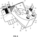
6 zeigt eine seitliche dreidimensionale Darstellung der weiter entlang der zylindrisch gewölbten Führungsflächen zueinander verschobenen Mutterteile derSchraubenmutter aus 5 . -
7 zeigt eine dreidimensionale schräge Draufsicht auf dieSchraubenmutter aus 6 . -
8 zeigt eine isolierte Darstellung des ersten Mutterteils der Schraubenmutter aus den5 -7 . -
9 zeigt eine isolierte Darstellung des zweiten Mutterteils der Schraubenmutter aus den5 -7 .
-
1 shows a three-dimensional oblique side view of a fastening and clamping arrangement with a two-part screw nut with pressure screws in the closed position of use. -
2 shows one of the1 Corresponding representation of the fastening and clamping arrangement in the half-open position. -
3 shows one of the1 and2 Corresponding representation of the fastening and clamping arrangement in the fully open position. -
4th shows one of the3 corresponding representation with the screw nut pushed away from the support surface. -
5 shows an enlarged and isolated three-dimensional representation of the nut from FIG4th in the open position. -
6th shows a lateral three-dimensional representation of the nut parts of the screw nut, which are further displaced along the cylindrically curved guide surfaces5 . -
7th shows a three-dimensional oblique top view of the nut from FIG6th . -
8th shows an isolated representation of the first nut part of the nut from FIGS5 -7th . -
9 FIG. 11 shows an isolated representation of the second nut part of the screw nut from FIG5 -7th .
Die
Das Mutterteil
Die beiden Verriegelungsarme 5,6 bzw. 7,8 der zwei Mutterteile
Entsprechend liegt die nach unten weisende Führungsfläche
Die Art der Schwenkbewegung, welche die zwei Mutterteile
Ein Verkippen der Mutterteile
Das Verschwenken entlang der zylindermantelförmig gewölbten Führungsflächen
Der Bewegungsablauf beim Verbinden der Mutterteile
Die Schraubmutter weist ferner Andrückschrauben
In
Dagegen ist die Andrückschraube
Um die Anordnung der Andrückschrauben
In der in
Die in der vorliegenden Beschreibung, in den Zeichnungen sowie in den Ansprüchen offenbarten Merkmale der Erfindung können sowohl einzeln als auch in beliebigen Kombinationen für die Verwirklichung der Erfindung in ihren verschiedenen Ausführungsformen wesentlich sein. Die Erfindung ist nicht auf die beschriebenen Ausführungsformen beschränkt. Sie kann im Rahmen der Ansprüche und unter Berücksichtigung der Kenntnisse des zuständigen Fachmanns variiert werden.The features of the invention disclosed in the present description, in the drawings and in the claims can be essential both individually and in any combination for the implementation of the invention in its various embodiments. The invention is not restricted to the embodiments described. It can be varied within the scope of the claims and taking into account the knowledge of the competent specialist.
Bezugszeichenliste List of reference symbols
- 11
- erstes Mutterteilfirst mother part
- 22
- zweites Mutterteilsecond nut part
- 33
- InnengewindeabschnittInternal thread section
- 44th
- InnengewindeabschnittInternal thread section
- 55
- VerriegelungsarmLocking arm
- 66th
- VerriegelungsarmLocking arm
- 77th
- VerriegelungsarmLocking arm
- 88th
- VerriegelungsarmLocking arm
- 99
- gewölbte Führungsflächecurved guide surface
- 1010
- gewölbte Führungsflächecurved guide surface
- 1111
- gewölbte Führungsflächecurved guide surface
- 1212
- gewölbte Führungsflächecurved guide surface
- 1313
- achsparallele Führungsflächeaxially parallel guide surface
- 1414th
- achsparallele Führungsflächeaxially parallel guide surface
- 1515th
- achsparallele Führungsflächeaxially parallel guide surface
- 1616
- achsparallele Führungsflächeaxially parallel guide surface
- 1717th
- achsparallele Führungsflächeaxially parallel guide surface
- 1818th
- achsparallele Führungsflächeaxially parallel guide surface
- 1919th
- achsparallele Führungsflächeaxially parallel guide surface
- 2020th
- achsparallele Führungsflächeaxially parallel guide surface
- 2121st
- erste axiale Endfläche, Unterseitefirst axial end face, underside
- 2222nd
- zweite axiale Endfläche, Oberseitesecond axial end face, upper side
- 2323
- Stützfläche Support surface
- 2525th
- AußengewindeExternal thread
- 2626th
- AndrückschraubePressure screw
- 2727
- AndrückschraubePressure screw
- 2828
- AndrückschraubePressure screw
- 2929
- AndrückschraubePressure screw
- 3030th
- AndrückschraubePressure screw
- 3131
- AndrückschraubePressure screw
- 3232
- GehäusewandabschnittHousing wall section
- 3333
- RingscheibeWasher
- 3434
- DruckabschnittPrint section
- 3535
- Sechskant-AufnahmeHexagon socket
- 3636
- AndrückgewindePressure thread
- 3737
- AndrückgewindePressure thread
- 3838
- AndrückgewindePressure thread
- 3939
- AndrückgewindePressure thread
- 4040
- AndrückgewindePressure thread
- 4141
- AndrückgewindePressure thread
- 4242
- Aussparung, LanglochRecess, elongated hole
- 4343
- Aussparung, LanglochRecess, elongated hole
ZITATE ENTHALTEN IN DER BESCHREIBUNG QUOTES INCLUDED IN THE DESCRIPTION
Diese Liste der vom Anmelder aufgeführten Dokumente wurde automatisiert erzeugt und ist ausschließlich zur besseren Information des Lesers aufgenommen. Die Liste ist nicht Bestandteil der deutschen Patent- bzw. Gebrauchsmusteranmeldung. Das DPMA übernimmt keinerlei Haftung für etwaige Fehler oder Auslassungen.This list of the documents listed by the applicant was generated automatically and is included solely for the better information of the reader. The list is not part of the German patent or utility model application. The DPMA assumes no liability for any errors or omissions.
Zitierte PatentliteraturPatent literature cited
- EP 1982082 B1 [0002, 0034, 0036, 0039, 0050]EP 1982082 B1 [0002, 0034, 0036, 0039, 0050]
- US 4621730 A [0037]US 4621730 A [0037]
- US 4927305 [0037]US 4927305 [0037]
- US 5075950 A [0037]US 5075950 A [0037]
- US 5083889 A [0037]US 5083889 A [0037]
- US 6112396 A [0037]US 6112396 A [0037]
Claims (6)
Priority Applications (3)
| Application Number | Priority Date | Filing Date | Title |
|---|---|---|---|
| PCT/EP2020/053373 WO2020169395A1 (en) | 2019-02-18 | 2020-02-11 | Two-piece threaded nut with high pressing force |
| EP20705033.7A EP3721102B1 (en) | 2019-02-18 | 2020-02-11 | Two-piece threaded nut with high pressing force |
| US17/431,755 US11644059B2 (en) | 2019-02-18 | 2020-02-11 | Two-part nut with high pressing force |
Applications Claiming Priority (2)
| Application Number | Priority Date | Filing Date | Title |
|---|---|---|---|
| DE102019104024 | 2019-02-18 | ||
| DE102019104024.8 | 2019-02-18 |
Publications (2)
| Publication Number | Publication Date |
|---|---|
| DE102019111237A1 true DE102019111237A1 (en) | 2020-08-20 |
| DE102019111237B4 DE102019111237B4 (en) | 2020-11-19 |
Family
ID=71843732
Family Applications (1)
| Application Number | Title | Priority Date | Filing Date |
|---|---|---|---|
| DE102019111237.0A Active DE102019111237B4 (en) | 2019-02-18 | 2019-04-30 | Two-part screw nut with high pressing force |
Country Status (4)
| Country | Link |
|---|---|
| US (1) | US11644059B2 (en) |
| EP (1) | EP3721102B1 (en) |
| DE (1) | DE102019111237B4 (en) |
| WO (1) | WO2020169395A1 (en) |
Cited By (1)
| Publication number | Priority date | Publication date | Assignee | Title |
|---|---|---|---|---|
| CN113340185A (en) * | 2021-06-25 | 2021-09-03 | 河南航天精工制造有限公司 | Lock nut compression deformation gauge and use method thereof |
Families Citing this family (1)
| Publication number | Priority date | Publication date | Assignee | Title |
|---|---|---|---|---|
| USD1015863S1 (en) * | 2022-05-20 | 2024-02-27 | Nord-Lock Switzerland Gmbh | Fastening device |
Citations (8)
| Publication number | Priority date | Publication date | Assignee | Title |
|---|---|---|---|---|
| US4621730A (en) * | 1985-04-02 | 1986-11-11 | Mancusi Jr Joseph J | Aerated soapholder |
| US4927305A (en) * | 1988-09-02 | 1990-05-22 | Peterson Charles D | Tightening device for threaded connectors |
| US5075950A (en) * | 1990-06-28 | 1991-12-31 | Steinbock Rolf H | Method for loosening jack bolts |
| US5083889A (en) * | 1990-10-04 | 1992-01-28 | Steinbock Rolf H | Structure for preventing escape of jack bolts in apparatus to mechanically stress a bolt-type fastener |
| DE69000653T2 (en) * | 1989-07-11 | 1993-05-19 | Hedley Purvis Ltd | QUICK FASTENING NUT. |
| US6112396A (en) * | 1998-06-10 | 2000-09-05 | Steinbock Machinery Co. | Jackbolts for multi jackbolt tensioners |
| GB2469829A (en) * | 2009-04-29 | 2010-11-03 | Tri Star Ind Pte Ltd | Quick release nut |
| EP1982082B1 (en) * | 2006-02-08 | 2012-04-11 | Dietmar Schnier | Nut having at least two parts |
Family Cites Families (8)
| Publication number | Priority date | Publication date | Assignee | Title |
|---|---|---|---|---|
| US2257327A (en) * | 1941-04-23 | 1941-09-30 | Carios L Bradford | Nut |
| US2377581A (en) * | 1944-03-09 | 1945-06-05 | Matthew J Shaffrey | Divided nut construction |
| US3038366A (en) * | 1959-10-15 | 1962-06-12 | Roy G Hindman | Separating nut assembly |
| US4078470A (en) * | 1976-02-02 | 1978-03-14 | Zeranick Jr Paul S | Split nut |
| US4622730A (en) | 1984-03-30 | 1986-11-18 | Rolf Steinbock | Apparatus to mechanically stress a bolt-type fastener |
| US4556352A (en) * | 1984-08-08 | 1985-12-03 | American Snap Nut Association | Shaft-mounted snap lock assembly |
| DK3471920T3 (en) | 2016-06-16 | 2023-04-03 | Superbolt Inc | IMPROVEMENTS OF MULTI JACK TIGHTENERS |
| WO2019014097A1 (en) | 2017-07-10 | 2019-01-17 | Superbolt, Inc. | Socket and socket attachment |
-
2019
- 2019-04-30 DE DE102019111237.0A patent/DE102019111237B4/en active Active
-
2020
- 2020-02-11 US US17/431,755 patent/US11644059B2/en active Active
- 2020-02-11 EP EP20705033.7A patent/EP3721102B1/en active Active
- 2020-02-11 WO PCT/EP2020/053373 patent/WO2020169395A1/en unknown
Patent Citations (8)
| Publication number | Priority date | Publication date | Assignee | Title |
|---|---|---|---|---|
| US4621730A (en) * | 1985-04-02 | 1986-11-11 | Mancusi Jr Joseph J | Aerated soapholder |
| US4927305A (en) * | 1988-09-02 | 1990-05-22 | Peterson Charles D | Tightening device for threaded connectors |
| DE69000653T2 (en) * | 1989-07-11 | 1993-05-19 | Hedley Purvis Ltd | QUICK FASTENING NUT. |
| US5075950A (en) * | 1990-06-28 | 1991-12-31 | Steinbock Rolf H | Method for loosening jack bolts |
| US5083889A (en) * | 1990-10-04 | 1992-01-28 | Steinbock Rolf H | Structure for preventing escape of jack bolts in apparatus to mechanically stress a bolt-type fastener |
| US6112396A (en) * | 1998-06-10 | 2000-09-05 | Steinbock Machinery Co. | Jackbolts for multi jackbolt tensioners |
| EP1982082B1 (en) * | 2006-02-08 | 2012-04-11 | Dietmar Schnier | Nut having at least two parts |
| GB2469829A (en) * | 2009-04-29 | 2010-11-03 | Tri Star Ind Pte Ltd | Quick release nut |
Cited By (1)
| Publication number | Priority date | Publication date | Assignee | Title |
|---|---|---|---|---|
| CN113340185A (en) * | 2021-06-25 | 2021-09-03 | 河南航天精工制造有限公司 | Lock nut compression deformation gauge and use method thereof |
Also Published As
| Publication number | Publication date |
|---|---|
| DE102019111237B4 (en) | 2020-11-19 |
| EP3721102B1 (en) | 2021-03-17 |
| EP3721102A1 (en) | 2020-10-14 |
| US20220136553A1 (en) | 2022-05-05 |
| US11644059B2 (en) | 2023-05-09 |
| WO2020169395A1 (en) | 2020-08-27 |
Similar Documents
| Publication | Publication Date | Title |
|---|---|---|
| DE102006005998B4 (en) | Nut with at least two parts | |
| DE3903354C1 (en) | ||
| DE4137286C2 (en) | Oil filter or fuel filter housing | |
| WO2012048686A1 (en) | Cage nut | |
| DE102009001535A1 (en) | Assembly, method of use of this assembly and tool for applying the method | |
| DE2737537C2 (en) | ||
| EP3004666A1 (en) | Screw | |
| EP2226517A1 (en) | Construction unit | |
| EP3132146B1 (en) | Fastening device | |
| EP3721102B1 (en) | Two-piece threaded nut with high pressing force | |
| EP1903223B1 (en) | Plastic Nut | |
| DE3009716C2 (en) | Securing element for a screw nut that can be placed on a threaded bolt | |
| DE102019118338B4 (en) | Torque drive head | |
| EP2304250B1 (en) | Screw clip | |
| DE10326660A1 (en) | Fastener with eccentric positioning discs has an upper section with profiled cross section to locate discs | |
| WO2008012074A1 (en) | Safety nut | |
| DE3149217A1 (en) | "QUARTER TURN NUT" | |
| DE202011051362U1 (en) | socket | |
| DE102019218637A1 (en) | Spindle drive and method for assembling a spindle drive | |
| WO2003011503A1 (en) | Spacer element for a collet chuck and collet chuck | |
| DE102015205623B4 (en) | Manual wrench | |
| DE10052915B4 (en) | Mother with a pinch lock | |
| DE2749196A1 (en) | SELF-LOCKING NUT | |
| DE102022100210A1 (en) | Two-part union nut | |
| DE3512425A1 (en) | Cavity-wall socket for electrical installation devices, especially switches, plug sockets or the like |
Legal Events
| Date | Code | Title | Description |
|---|---|---|---|
| R012 | Request for examination validly filed | ||
| R016 | Response to examination communication | ||
| R018 | Grant decision by examination section/examining division | ||
| R020 | Patent grant now final |