EP0114923B1 - Verfahren und Einrichtung zum Trennen verschiedenartiger Bestandteile - Google Patents
Verfahren und Einrichtung zum Trennen verschiedenartiger Bestandteile Download PDFInfo
- Publication number
- EP0114923B1 EP0114923B1 EP83107380A EP83107380A EP0114923B1 EP 0114923 B1 EP0114923 B1 EP 0114923B1 EP 83107380 A EP83107380 A EP 83107380A EP 83107380 A EP83107380 A EP 83107380A EP 0114923 B1 EP0114923 B1 EP 0114923B1
- Authority
- EP
- European Patent Office
- Prior art keywords
- heavy
- medium
- chamber
- separator according
- lifting chamber
- Prior art date
- Legal status (The legal status is an assumption and is not a legal conclusion. Google has not performed a legal analysis and makes no representation as to the accuracy of the status listed.)
- Expired
Links
- 238000000034 method Methods 0.000 title abstract description 3
- 239000000463 material Substances 0.000 claims abstract description 52
- 239000002245 particle Substances 0.000 claims abstract description 9
- 239000007788 liquid Substances 0.000 claims abstract description 4
- 238000005192 partition Methods 0.000 claims description 15
- 239000000470 constituent Substances 0.000 claims 1
- 238000007667 floating Methods 0.000 abstract description 19
- 239000006185 dispersion Substances 0.000 abstract 1
- 239000007787 solid Substances 0.000 abstract 1
- 239000010802 sludge Substances 0.000 description 16
- 239000002002 slurry Substances 0.000 description 13
- 238000009412 basement excavation Methods 0.000 description 10
- 238000000926 separation method Methods 0.000 description 4
- 239000002184 metal Substances 0.000 description 3
- 229910052751 metal Inorganic materials 0.000 description 3
- XEEYBQQBJWHFJM-UHFFFAOYSA-N Iron Chemical compound [Fe] XEEYBQQBJWHFJM-UHFFFAOYSA-N 0.000 description 2
- 238000011109 contamination Methods 0.000 description 2
- 230000005484 gravity Effects 0.000 description 2
- 150000002739 metals Chemical class 0.000 description 2
- 230000015572 biosynthetic process Effects 0.000 description 1
- 230000000903 blocking effect Effects 0.000 description 1
- 239000003245 coal Substances 0.000 description 1
- 238000000605 extraction Methods 0.000 description 1
- 229910052742 iron Inorganic materials 0.000 description 1
- 238000003754 machining Methods 0.000 description 1
- 238000005065 mining Methods 0.000 description 1
- 238000002360 preparation method Methods 0.000 description 1
- 238000011084 recovery Methods 0.000 description 1
- 238000004064 recycling Methods 0.000 description 1
- 239000008237 rinsing water Substances 0.000 description 1
- 238000005204 segregation Methods 0.000 description 1
- 230000007704 transition Effects 0.000 description 1
Images
Classifications
-
- B—PERFORMING OPERATIONS; TRANSPORTING
- B03—SEPARATION OF SOLID MATERIALS USING LIQUIDS OR USING PNEUMATIC TABLES OR JIGS; MAGNETIC OR ELECTROSTATIC SEPARATION OF SOLID MATERIALS FROM SOLID MATERIALS OR FLUIDS; SEPARATION BY HIGH-VOLTAGE ELECTRIC FIELDS
- B03B—SEPARATING SOLID MATERIALS USING LIQUIDS OR USING PNEUMATIC TABLES OR JIGS
- B03B5/00—Washing granular, powdered or lumpy materials; Wet separating
- B03B5/28—Washing granular, powdered or lumpy materials; Wet separating by sink-float separation
- B03B5/30—Washing granular, powdered or lumpy materials; Wet separating by sink-float separation using heavy liquids or suspensions
- B03B5/36—Devices therefor, other than using centrifugal force
- B03B5/42—Devices therefor, other than using centrifugal force of drum or lifting wheel type
-
- Y—GENERAL TAGGING OF NEW TECHNOLOGICAL DEVELOPMENTS; GENERAL TAGGING OF CROSS-SECTIONAL TECHNOLOGIES SPANNING OVER SEVERAL SECTIONS OF THE IPC; TECHNICAL SUBJECTS COVERED BY FORMER USPC CROSS-REFERENCE ART COLLECTIONS [XRACs] AND DIGESTS
- Y02—TECHNOLOGIES OR APPLICATIONS FOR MITIGATION OR ADAPTATION AGAINST CLIMATE CHANGE
- Y02W—CLIMATE CHANGE MITIGATION TECHNOLOGIES RELATED TO WASTEWATER TREATMENT OR WASTE MANAGEMENT
- Y02W30/00—Technologies for solid waste management
- Y02W30/50—Reuse, recycling or recovery technologies
- Y02W30/64—Paper recycling
Definitions
- the invention relates to a sink separator for separating various types of bastand parts of a reprocessed material, with a container containing a slurry that is divided into a sinking chamber and a lifting chamber that communicates with it by means of a partition wall that extends from above the debris level into the slurry, with floating material floating in the sinking chamber to the liquid level is to be discharged to the outside via an overflow weir and the sunk material which has sunk to the bottom of the container is to be lifted out of the container by means of a driven paddle wheel which is arranged in the lifting chamber and can be rotated outward from the paddle wheel.
- Sink separators which are known in various configurations, have long been used in mining for the processing of coal and ore. More recently, they have also been used for recycling various materials, for example metals, with a preferred area of application being the recovery of valuable metals from scrap, in particular automobile scrap.
- the subject matter of the present invention is also determined and suitable for this in a special way.
- the processed material is put into or placed on a heavy sludge, whereby the so-called floating material, the specific weight of which is lighter than the specific weight of the heavy sludge, is subtracted from the surface of the heavy sludge and the sinking material, the specific weight of which is greater than that of the clouded cloud from which the clouded cloud is lifted.
- the reprocessed material usually also contains components that have approximately the same specific weight as the heavy sludge and consequently float in the heavy sludge.
- the present invention has for its object to provide a generic sink separator with high selectivity, which is particularly suitable for processing automobile scrap, whereby on the one hand it should be ensured that as little floating material as possible gets into the removal chamber and is discharged from it together with the sink material and, on the other hand, that the sinking material supplied to the excavation chamber can be discharged without any problems.
- the axis of rotation of the impeller runs parallel to the partition, that the blades of the impeller are open at the periphery and that the direction of rotation of the impeller is directed such that the lower section of the circular path of movement of the blades is between the partition and the gap formed in the bottom is executed such that the container bottom in the region of the lifting chamber is designed in a circular arc to match the radially outward movement path of the blades, and that the heavy turbidity flow in the sinking chamber runs parallel to the partition wall or to the axis of rotation of the blade wheel, in which Sink chamber a laminar flow is present.
- the relatively narrow gap between the underside of the dividing wall and the container bottom can have the same height over its length, increase in its embodiment over its length with respect to its height, and can be wedge-shaped.
- the sink chamber floor merges continuously into the excavation chamber floor in order to prevent any formation of nests and the possibility of wedging.
- the blades of the paddle wheel are at a minimum distance from the bottom of the excavation chamber, which corresponds to approximately a quarter of the (average) particle size of the material to be sinked, since it has been shown that the excavation chamber is then largely emptied by the paddle wheel is.
- the smallest distance between the blades in the area of the dividing wall is preferably larger and corresponds approximately to the (average) particle size of the material to be sinked, with no wedging of any kind.
- both the sinking chamber and the lifting chamber each have a heavy slurry inflow, the heavy slurry inflow for the sinking chamber preferably being arranged at a relatively short distance below the heavy slurry level, while the heavy slurry inflow of the lifting chamber can preferably be arranged adjacent to the lifting chamber floor .
- Such a configuration favors the laminar flow provided according to the invention there in the sink chamber and, with a suitable arrangement, can help to quickly discharge the floating material.
- the arrangement of the heavy turbidity flow in the excavation chamber near the ground has proven to be expedient because it may remove deposits, or because deposits of this type do not even occur. For the rest, it has proven expedient to create ideal separation conditions if the heavy slurry inflows for the sink chamber and the excavation chamber are arranged in opposite directions to one another.
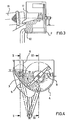
- the drawing shows a sink separator with a container 12 containing heavy sludge, which is subdivided into a sinking chamber 1 and a lifting chamber 2 communicating with it by means of a partition wall 6 extending from above the heavy sludge level (see FIG. 4).
- the bottom 3 of the sink chamber 1 is designed with a slope in the direction of the lifting chamber 2 and merges into the bottom 4 of the lifting chamber 2 in the region of the partition 6.
- the sinking material is lifted out of the lifting chamber 2 by means of a paddle wheel which has a rotating arm 8, on the outer ends of which a paddle 7 is arranged.
- the arm 8 is arranged in such a way that the blades 7 rotate at a minimum distance from the bottom 4 of the extraction chamber 2, which is of circular arc shape in cross section, corresponding to a quarter of the average particle size of the material to be processed.
- the smallest distance between the blades 7 corresponds approximately to the average particle size of the material to be processed.
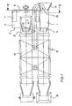
- Both the sink chamber 2 and the lifting chamber 3 each have a heavy slurry inflow 10 (see FIG. 1).
- the heavy slurry inflow 10 in the sink chamber 1 is arranged at a relatively short distance below the heavy slurry level.
- the heavy slurry inflow 10 is arranged in the excavation chamber 2 in the region of the bottom 4.
- the heavy turbidity inflows 10, 10 of the sink chamber 1 and the excavation chamber 2 are arranged in such a way that the flow directions are opposite to each other.
- the operation of the sink separator according to the invention is as follows:
- the material to be processed is fed into the sink chamber 1 via a chute 13.
- the sink chamber 1 there is a laminar flow generated by the incoming heavy sludge, so that the floating material is introduced via a weir edge and a chute 14 into a first drum screen 15, where it is separated in the first section on a drip line from heavy sludge still adhering to it.
- the floating material is cleaned by a rinsing water circuit.
- the floating material is then passed directly from the drum screen 15 into a collecting container 16.
- the gravity drops following gravity in the sink chamber 1 from the bottom 3, where the sinking movement is diverted by the oblique design of the bottom 3 into a lateral movement in the direction of the lifting chamber 2.
- the paddle wheel 7, 8 arranged in the lifting chamber 2 is driven by an electric drive, not shown in the drawing.
- the blades 7 are rotated so that they perform an upward movement in the area of the partition 6.
- the sunken heavy cargo is partially already recorded before it has reached the bottom 4 of the excavation chamber 2.
- a blade 7 of the blade wheel 7, 8 has reached its upper position, the material contained in it falls into a chute 17, from which it slides into a drum screen 18, in which it is separated from the heavy sludge in the same way and then rinsed , as described above with reference to the floating material.
- a magnetic drum is arranged in the outlet of the drum screen 18, from which the sieved material is either passed onto a picking belt or into a container.
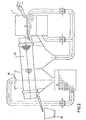
- FIG. 2 shows a longitudinal section through the sink chamber 1 with the associated pipeline and pump system, the drum screen 15 also being recognizable for the floating material.
- the sieve openings of the drum sieve 15 and the drum sieve 18 are dimensioned such that the smallest parts of the material to be processed fall through and are circulated with the heavy sludge through the piping system and the pumps. This constantly agitates the sludge in the entire system, so that deposits cannot form or segregate in any part.
- the screen openings are then dimensioned such that no reprocessed material can fall through.
Landscapes
- Separation Of Solids By Using Liquids Or Pneumatic Power (AREA)
- Combined Means For Separation Of Solids (AREA)
- Physical Water Treatments (AREA)
- Control And Other Processes For Unpacking Of Materials (AREA)
- Processing Of Solid Wastes (AREA)
- Filters For Electric Vacuum Cleaners (AREA)
- Automatic Assembly (AREA)
- Window Of Vehicle (AREA)
- Switches That Are Operated By Magnetic Or Electric Fields (AREA)
- Manufacture And Refinement Of Metals (AREA)
- Disintegrating Or Milling (AREA)
- Sampling And Sample Adjustment (AREA)
- Processing And Handling Of Plastics And Other Materials For Molding In General (AREA)
Priority Applications (1)
| Application Number | Priority Date | Filing Date | Title |
|---|---|---|---|
| AT83107380T ATE22235T1 (de) | 1983-01-26 | 1983-07-27 | Verfahren und einrichtung zum trennen verschiedenartiger bestandteile. |
Applications Claiming Priority (2)
| Application Number | Priority Date | Filing Date | Title |
|---|---|---|---|
| DE3302490 | 1983-01-26 | ||
| DE3302490A DE3302490C2 (de) | 1983-01-26 | 1983-01-26 | Sinkscheider |
Publications (3)
| Publication Number | Publication Date |
|---|---|
| EP0114923A2 EP0114923A2 (de) | 1984-08-08 |
| EP0114923A3 EP0114923A3 (en) | 1985-01-23 |
| EP0114923B1 true EP0114923B1 (de) | 1986-09-17 |
Family
ID=6189222
Family Applications (1)
| Application Number | Title | Priority Date | Filing Date |
|---|---|---|---|
| EP83107380A Expired EP0114923B1 (de) | 1983-01-26 | 1983-07-27 | Verfahren und Einrichtung zum Trennen verschiedenartiger Bestandteile |
Country Status (14)
| Country | Link |
|---|---|
| US (1) | US4612114A (pt) |
| EP (1) | EP0114923B1 (pt) |
| JP (1) | JPS60202752A (pt) |
| AT (1) | ATE22235T1 (pt) |
| AU (1) | AU564836B2 (pt) |
| BR (1) | BR8400215A (pt) |
| CA (1) | CA1215680A (pt) |
| DD (1) | DD214535A5 (pt) |
| DE (2) | DE3302490C2 (pt) |
| DK (1) | DK168880B1 (pt) |
| ES (1) | ES529147A0 (pt) |
| MX (1) | MX160141A (pt) |
| SU (1) | SU1417789A3 (pt) |
| ZA (1) | ZA84559B (pt) |
Families Citing this family (4)
| Publication number | Priority date | Publication date | Assignee | Title |
|---|---|---|---|---|
| DE3743768A1 (de) * | 1987-12-23 | 1989-07-13 | He Anlagentechnik Hellmich Gmb | Sinkscheider, insbesondere zum trennen von schreddergut |
| GB9021353D0 (en) * | 1990-10-01 | 1990-11-14 | Breach John R | Sorting by size |
| ES2136501B1 (es) * | 1996-07-09 | 2000-07-01 | Carbonifera Del Ebro S A | Procedimiento mejorado de separacion del carbon y los esteriles en una extraccion carbonifera. |
| US20080135461A1 (en) * | 2006-12-06 | 2008-06-12 | Olivier Paul A | Dense medium separator |
Family Cites Families (20)
| Publication number | Priority date | Publication date | Assignee | Title |
|---|---|---|---|---|
| NL70132C (pt) * | ||||
| BE517515A (pt) * | ||||
| FR547648A (pt) * | 1922-12-20 | |||
| US763662A (en) * | 1903-03-09 | 1904-06-28 | Broken Hill Pty Co Ltd | Apparatus for use in certain processes of extracting sulfids from ores. |
| DE408007C (de) * | 1918-07-18 | 1925-01-08 | Josef Haeusler | Einrichtung zum Sortieren von staubfoermigem Gut |
| US1943861A (en) * | 1931-06-18 | 1934-01-16 | Friberg Harry Adolph | Sand washing apparatus |
| US2590756A (en) * | 1946-05-10 | 1952-03-25 | Mines Domaniales De Potasse | Art of mineral separation |
| US2496703A (en) * | 1947-02-19 | 1950-02-07 | Hilmer N Ekbom | Three-way gravity liquid separation |
| FR1060836A (fr) * | 1952-02-16 | 1954-04-06 | Jaruza A G Chur | Appareil de classification densimétrique, par liqueur de?se, de produits solides dedensités différentes |
| FR1141248A (fr) * | 1955-02-14 | 1957-08-28 | Schuechtermann & Kremer | Appareil de séparation par flottation |
| US3019900A (en) * | 1958-12-02 | 1962-02-06 | Prep Ind Combustibles | Dense liquid media type separator |
| US3249226A (en) * | 1961-10-05 | 1966-05-03 | Orris L Watson | Method of and apparatus for heavy media separation |
| GB974120A (en) * | 1962-10-31 | 1964-11-04 | Gen Electric Co Ltd | Improvements in or relating to the separation of minerals |
| LU50208A1 (pt) * | 1965-01-15 | 1966-03-07 | ||
| PL78313B2 (pt) * | 1972-10-11 | 1975-06-30 | Centralny Osrodek Badawczoprojektowy Wzbogacania I | |
| AU6217373A (en) * | 1972-11-13 | 1975-05-08 | Luria Brothers & Co Inc | Flotation separation process |
| JPS51111956A (en) * | 1975-03-27 | 1976-10-02 | Yukio Nakajima | Apparatus for removing foreign materials in gravel |
| BE853969A (fr) * | 1976-04-29 | 1977-08-16 | Simonacco Ltd | Appareil en vue de separer des matieres solides ayant des poids specifiques differents |
| US4230561A (en) * | 1979-04-02 | 1980-10-28 | Mcmurray Russell L | Method and apparatus for separating clay from coal fines |
| US4409098A (en) * | 1982-03-29 | 1983-10-11 | Burke Billy T | Apparatus for separating a material of lighter specific gravity from a material of heavier specific gravity |
-
1983
- 1983-01-26 DE DE3302490A patent/DE3302490C2/de not_active Expired
- 1983-07-27 AT AT83107380T patent/ATE22235T1/de not_active IP Right Cessation
- 1983-07-27 DE DE8383107380T patent/DE3366293D1/de not_active Expired
- 1983-07-27 EP EP83107380A patent/EP0114923B1/de not_active Expired
- 1983-08-01 DK DK351483A patent/DK168880B1/da active
-
1984
- 1984-01-16 DD DD84259416A patent/DD214535A5/de not_active IP Right Cessation
- 1984-01-18 BR BR8400215A patent/BR8400215A/pt not_active IP Right Cessation
- 1984-01-24 JP JP59011775A patent/JPS60202752A/ja active Pending
- 1984-01-24 AU AU23739/84A patent/AU564836B2/en not_active Ceased
- 1984-01-25 ES ES529147A patent/ES529147A0/es active Granted
- 1984-01-25 SU SU843694949A patent/SU1417789A3/ru active
- 1984-01-25 ZA ZA84559A patent/ZA84559B/xx unknown
- 1984-01-25 CA CA000446054A patent/CA1215680A/en not_active Expired
- 1984-01-25 MX MX200138A patent/MX160141A/es unknown
-
1985
- 1985-07-16 US US06/755,549 patent/US4612114A/en not_active Expired - Fee Related
Also Published As
| Publication number | Publication date |
|---|---|
| DE3302490A1 (de) | 1984-08-02 |
| CA1215680A (en) | 1986-12-23 |
| JPS60202752A (ja) | 1985-10-14 |
| DK351483D0 (da) | 1983-08-01 |
| DE3366293D1 (en) | 1986-10-23 |
| US4612114A (en) | 1986-09-16 |
| ZA84559B (en) | 1984-09-26 |
| EP0114923A2 (de) | 1984-08-08 |
| ES8503527A1 (es) | 1985-04-01 |
| EP0114923A3 (en) | 1985-01-23 |
| SU1417789A3 (ru) | 1988-08-15 |
| AU2373984A (en) | 1984-08-02 |
| DD214535A5 (de) | 1984-10-17 |
| DK351483A (da) | 1984-07-27 |
| BR8400215A (pt) | 1984-08-28 |
| AU564836B2 (en) | 1987-08-27 |
| ATE22235T1 (de) | 1986-10-15 |
| MX160141A (es) | 1989-12-06 |
| ES529147A0 (es) | 1985-04-01 |
| DE3302490C2 (de) | 1985-09-05 |
| DK168880B1 (da) | 1994-07-04 |
Similar Documents
| Publication | Publication Date | Title |
|---|---|---|
| DE3885471T2 (de) | Zentrifugale Verdichtungsmaschine. | |
| DE2201188C3 (de) | Verfahren und Vorrichtung zum Abtrennen von Teilchen aus einer Flüssigkeit in einem Becken | |
| US3795316A (en) | Industrial waste processing apparatus | |
| DE2813056A1 (de) | Trennvorrichtung zum wiedergewinnen der zuschlagstoffe aus nicht-abgebundenem beton | |
| DE3333777C2 (pt) | ||
| EP0114923B1 (de) | Verfahren und Einrichtung zum Trennen verschiedenartiger Bestandteile | |
| DE2711854A1 (de) | Reinigungsgeraet zum abscheiden von magnetischen und nichtmagnetischen partikeln aus fluessigkeiten | |
| DE661897C (de) | Vorrichtung zum Aufbereiten von Steinkohle oder sonstigen Stoffen mittels Schwerfluessigkeit | |
| DE69308594T2 (de) | Einrichtung zur sink-schwimmscheidung von festen partikeln | |
| DE2803164C2 (pt) | ||
| DE910402C (de) | Schwerfluessigkeitsscheider | |
| DE626669C (de) | Verfahren und Vorrichtung zur Scheidung der organischen Feststoffe von den anorganischen in Abwaessern | |
| DE102006013256B4 (de) | Vorrichtung und Verfahren zum Entfernen von Partikeln aus einer Flüssigkeit | |
| DE588818C (de) | Verfahren zur Filtration sich rasch absetzender mineralischer Trueben | |
| WO2021121632A1 (de) | Waschen von schüttgut | |
| DE427401C (de) | Mit einer Fluessigkeit mittlerer Dichte arbeitende Vorrichtung zum Scheiden koernigen Gutes nach dem spezifischen Gewicht | |
| DE20018715U1 (de) | Sandfanganlage | |
| DE814581C (de) | Vorrichtung zum Klassieren von in einer Fluessigkeit suspendierten Feststoffen | |
| DE727441C (de) | Vorrichtung zur Aufbereitung von Kohle, Erz o. dgl. mittels Schwerfluessigkeit | |
| EP0593144B1 (de) | Entwässerungs-Schöpfrad | |
| DE2200548C3 (de) | Vorrichtung zum Räumen von abgesetzten Feststoffen oder von der schwersten Phase in Mehrphasen-Gemischen in Absetzbecken o.dgl | |
| DE1120393B (de) | Hubrad-Sinkscheider | |
| DE475040C (de) | Verfahren und Vorrichtung zur Aufbereitung und Veredelung von Verwitterungs- und Absetzmassen, wie Kaolin, Asbest, Kreide u. dgl. | |
| AT81960B (de) | Verfahren und Vorrichtung zum Abscheiden von Schwimmstoffen aus Flüssigkeiten. | |
| DE3738508A1 (de) | Ein- und zweizellenaufbereitungsanlage der schwertruebe sowie satz von aufbereitungsanlagen, besonders von ein- sowie zwei- und einzellenaufbereitungsanlagen der schwertruebe, besonders ein dreiproduktsatz |
Legal Events
| Date | Code | Title | Description |
|---|---|---|---|
| PUAI | Public reference made under article 153(3) epc to a published international application that has entered the european phase |
Free format text: ORIGINAL CODE: 0009012 |
|
| AK | Designated contracting states |
Designated state(s): AT BE CH DE FR GB IT LI LU NL SE |
|
| PUAL | Search report despatched |
Free format text: ORIGINAL CODE: 0009013 |
|
| AK | Designated contracting states |
Designated state(s): AT BE CH DE FR GB IT LI LU NL SE |
|
| 17P | Request for examination filed |
Effective date: 19850131 |
|
| ITF | It: translation for a ep patent filed | ||
| GRAA | (expected) grant |
Free format text: ORIGINAL CODE: 0009210 |
|
| AK | Designated contracting states |
Kind code of ref document: B1 Designated state(s): AT BE CH DE FR GB IT LI LU NL SE |
|
| REF | Corresponds to: |
Ref document number: 22235 Country of ref document: AT Date of ref document: 19861015 Kind code of ref document: T |
|
| REF | Corresponds to: |
Ref document number: 3366293 Country of ref document: DE Date of ref document: 19861023 |
|
| ET | Fr: translation filed | ||
| PLBE | No opposition filed within time limit |
Free format text: ORIGINAL CODE: 0009261 |
|
| STAA | Information on the status of an ep patent application or granted ep patent |
Free format text: STATUS: NO OPPOSITION FILED WITHIN TIME LIMIT |
|
| 26N | No opposition filed | ||
| ITTA | It: last paid annual fee | ||
| PGFP | Annual fee paid to national office [announced via postgrant information from national office to epo] |
Ref country code: FR Payment date: 19940711 Year of fee payment: 12 |
|
| PGFP | Annual fee paid to national office [announced via postgrant information from national office to epo] |
Ref country code: AT Payment date: 19940714 Year of fee payment: 12 |
|
| PGFP | Annual fee paid to national office [announced via postgrant information from national office to epo] |
Ref country code: GB Payment date: 19940719 Year of fee payment: 12 |
|
| PGFP | Annual fee paid to national office [announced via postgrant information from national office to epo] |
Ref country code: DE Payment date: 19940721 Year of fee payment: 12 |
|
| PGFP | Annual fee paid to national office [announced via postgrant information from national office to epo] |
Ref country code: CH Payment date: 19940725 Year of fee payment: 12 |
|
| PGFP | Annual fee paid to national office [announced via postgrant information from national office to epo] |
Ref country code: SE Payment date: 19940731 Year of fee payment: 12 Ref country code: NL Payment date: 19940731 Year of fee payment: 12 Ref country code: LU Payment date: 19940731 Year of fee payment: 12 |
|
| PGFP | Annual fee paid to national office [announced via postgrant information from national office to epo] |
Ref country code: BE Payment date: 19940912 Year of fee payment: 12 |
|
| EPTA | Lu: last paid annual fee | ||
| EAL | Se: european patent in force in sweden |
Ref document number: 83107380.4 |
|
| PG25 | Lapsed in a contracting state [announced via postgrant information from national office to epo] |
Ref country code: LU Free format text: LAPSE BECAUSE OF NON-PAYMENT OF DUE FEES Effective date: 19950727 Ref country code: GB Effective date: 19950727 Ref country code: AT Effective date: 19950727 |
|
| PG25 | Lapsed in a contracting state [announced via postgrant information from national office to epo] |
Ref country code: SE Effective date: 19950728 |
|
| PG25 | Lapsed in a contracting state [announced via postgrant information from national office to epo] |
Ref country code: LI Effective date: 19950731 Ref country code: CH Effective date: 19950731 Ref country code: BE Effective date: 19950731 |
|
| BERE | Be: lapsed |
Owner name: CARL KIESOW ROHSTOFFRUCKGEWINNUNG Effective date: 19950731 |
|
| PG25 | Lapsed in a contracting state [announced via postgrant information from national office to epo] |
Ref country code: NL Effective date: 19960201 |
|
| REG | Reference to a national code |
Ref country code: CH Ref legal event code: PL |
|
| GBPC | Gb: european patent ceased through non-payment of renewal fee |
Effective date: 19950727 |
|
| NLV4 | Nl: lapsed or anulled due to non-payment of the annual fee |
Effective date: 19960201 |
|
| PG25 | Lapsed in a contracting state [announced via postgrant information from national office to epo] |
Ref country code: DE Effective date: 19960402 |
|
| EUG | Se: european patent has lapsed |
Ref document number: 83107380.4 |
|
| PG25 | Lapsed in a contracting state [announced via postgrant information from national office to epo] |
Ref country code: FR Effective date: 19960430 |
|
| REG | Reference to a national code |
Ref country code: FR Ref legal event code: ST |
|
| REG | Reference to a national code |
Ref country code: FR Ref legal event code: ST |
|
| REG | Reference to a national code |
Ref country code: FR Ref legal event code: ST |