EP0112551B1 - Doppelbartschloss mit Riegel und Baskülestangen - Google Patents
Doppelbartschloss mit Riegel und Baskülestangen Download PDFInfo
- Publication number
- EP0112551B1 EP0112551B1 EP83112897A EP83112897A EP0112551B1 EP 0112551 B1 EP0112551 B1 EP 0112551B1 EP 83112897 A EP83112897 A EP 83112897A EP 83112897 A EP83112897 A EP 83112897A EP 0112551 B1 EP0112551 B1 EP 0112551B1
- Authority
- EP
- European Patent Office
- Prior art keywords
- lock
- bolt
- lock case
- locking bars
- actuates
- Prior art date
- Legal status (The legal status is an assumption and is not a legal conclusion. Google has not performed a legal analysis and makes no representation as to the accuracy of the status listed.)
- Expired
Links
- 239000002184 metal Substances 0.000 claims abstract description 5
- 229910052751 metal Inorganic materials 0.000 claims abstract description 5
- 238000005452 bending Methods 0.000 claims 1
- 238000004519 manufacturing process Methods 0.000 description 3
- 238000003892 spreading Methods 0.000 description 3
- 229910000831 Steel Inorganic materials 0.000 description 1
- 229910000746 Structural steel Inorganic materials 0.000 description 1
- 238000009434 installation Methods 0.000 description 1
- 238000000034 method Methods 0.000 description 1
- 238000003825 pressing Methods 0.000 description 1
- 238000004080 punching Methods 0.000 description 1
- 239000010959 steel Substances 0.000 description 1
Images

Classifications
-
- E—FIXED CONSTRUCTIONS
- E05—LOCKS; KEYS; WINDOW OR DOOR FITTINGS; SAFES
- E05C—BOLTS OR FASTENING DEVICES FOR WINGS, SPECIALLY FOR DOORS OR WINDOWS
- E05C9/00—Arrangements of simultaneously actuated bolts or other securing devices at well-separated positions on the same wing
- E05C9/04—Arrangements of simultaneously actuated bolts or other securing devices at well-separated positions on the same wing with two sliding bars moved in opposite directions when fastening or unfastening
Definitions
- the invention relates to a double-bit lock with deadbolt and base bars, which is mounted in a lock case with a lid and in which the bolt drives two opposite base legs provided with oblique slots via a driving pin.
- This lock has a deep-drawn lock case, the bottom of which carries the bolt with the tumblers.
- the bolt is guided in a recess in the lock case.
- a key arbor and a bearing pin for an eccentric disc are riveted to the box bottom. This is driven by a pin connected to the bolt and moves the oblique slots provided with oblique slots via two drive pins.
- the rods moving in opposite directions are guided in the side recesses of the lock case.
- lock case cover which also carries a significantly reinforced key guide.
- the lid carries two guide pins for the base brace. The lid is attached with several screws.
- the lock cover When the lock is dispatched and stored, the bulky parachute bars are removed.
- the lock cover When assembling the lock, the lock cover must be removed and screwed in after inserting the bascule rods before the lock can be attached to the back of the door. Appropriate operations are required if the lock needs to be readjusted.
- the invention has for its object to simplify and cheapen the manufacture and assembly of the castle.
- the lock case consists of a folded sheet metal, that the base bars are mounted behind the lock case, and that the driving pin attached to the bolt reaches through a slot in the lock case and drives the base bars.
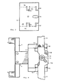
- Fig. 1 denotes the rectangular lock plate, from which the keyhole 2, a mortise 3 and a guide slot 4 are punched out.
- the side walls 5a, 5b of the rear lock case are drawn with broken lines.
- a key guide pin 16 is riveted to the lock case.
- the bolt 6 In the lock case the bolt 6 is mounted, which at its left end merges into an angle iron 7 with two locking bolts 8, 9.
- a rectangular locking pin 10 is riveted to the bolt 6, which engages in the tumblers and is guided in the slot 4.
- the hidden tumblers are pivotally mounted on the pin 11.
- the base bars 12, 13 are slidably arranged on the back of the lock case, as can be seen in FIG. 2.
- a driving pin 14 is riveted to the bolt 16.
- Fig. 3 shows a pre-punched plate of the lock case 5.
- the guide tabs 5c-5f are created by punching out U- or L-shaped slots and then folding along the dash-dotted lines.
- the elongated hole 5g serves as a guideway for the driving pin 14 and thus also the bolt 6.
- Fig. 4 shows the top view of the lock case and the base bars.
- the bolt 6, the locking bolts 8, 9 and the shortened base tubes 12, 13 are drawn in the extended state, that is, in the locked position.
- the base rod 12 lies under the rod 13. Both rods are extended beyond the driving mandrel 14 to such an extent that they are guided laterally by all four tabs 5c, 5d, 5e, 5f.
- the rods are held securely on the lock case 5 by the spreading spring 15.
- the driving pin 14 penetrates oblique slots 12a, 13a. When the drifting pin moves with the bolt 6 to the right by the closing path, the bascule rods are withdrawn from the lock.
- the best way to put the invention into practice is to keep as many components of the known double-bit lock as possible and to manufacture the lock case from band steel in a multi-stage stamping and folding tool.
- the lock described has the great advantage that the lock case does not have to be dismantled during installation.
- the lock is screwed to the cabinet door; Then the baskets are inserted into the lock and door guides and locked only by pressing on the spreading spring.
Landscapes
- Engineering & Computer Science (AREA)
- Mechanical Engineering (AREA)
- Gripping Jigs, Holding Jigs, And Positioning Jigs (AREA)
- Joining Of Building Structures In Genera (AREA)
- Holders For Apparel And Elements Relating To Apparel (AREA)
- Assembled Shelves (AREA)
- Lock And Its Accessories (AREA)
- Underground Structures, Protecting, Testing And Restoring Foundations (AREA)
- Clamps And Clips (AREA)
- Insertion Pins And Rivets (AREA)
Description
- Die Erfindung bezieht sich auf ein Doppelbartschloss mit Riegel und Baskülestangen, das in einem Schlosskasten mit Deckel montiert ist und bei welchem der Riegel über einen Treibdorn zwei gegenläufige, mit schrägen Schlitzen versehene Baskülestangen antreibt.
- Aus der 1977 veröffentlichten Liste G 77, Seite 15, der Firma Steinbach&Vollmann, 5628 Heiligenhaus, ist ein Wandschrankschloss mit Doppelbartschlüssel, Riegel und Baskülestangen der eingangs genannten Art bekannt geworden. Dieses Schloss weist einen tiefgezogenen Schlosskasten auf, dessen Boden den Riegel mit den Zuhaltungen trägt. Der Riegel ist in einer Aussparung des Schlosskastens geführt. Mit dem Kastenboden ist sowohl ein Schlüsseldorn als auch ein Lagerzapfen für eine Exzenterscheibe vernietet. Diese wird über einen mit dem Riegel verbundenen Zapfen angetrieben und bewegt über zwei Treibdorne die mit schrägen Schlitzen versehenen Baskülestangen. Die gegenläufig bewegten Stangen sind in seitlichen Aussparungen des Schlosskastens geführt. Alle beweglichen Teile werden durch einen Schlosskastendeckel zusammengehalten, der auch eine wesentlich verstärkte Schlüsselführung trägt. Weiterhin trägt der Deckel zwei Führungsdorne für die Baskülestangen. Der Deckel ist mit mehreren Schrauben befestigt. Bei Versand und Lagerung des Schlosses sind die sperrigen Baskülestangen abgenommen. Bei der Montage des Schlosses muss der Schlossdeckel abgenommen und nach dem Einlegen der Baskülestangen festgeschraubt werden, bevor das Schloss an der Türrückseite befestigt werden kann. Entsprechende Arbeitsgänge sind erforderlich, wenn das Schloss nachjustiert werden muss.
- Der Erfindung liegt die Aufgabe zugrunde, die Herstellung und Montage des Schlosses zu vereinfachen und zu verbilligen.
- Diese Aufgabe wird dadurch gelöst, dass der Schlosskasten aus einem abgekanteten Blech besteht, dass die Baskülestangen hinter dem Schlosskasten gelagert sind und dass der auf dem Riegel befestigte Treibdorn durch einen Schlitz des Schlosskastens hindurchgreift und die Baskülestangen antreibt.
- Ein Ausführungsbeispiel der Erfindung wird anhand von Fig. 1-4 der Zeichnungen erläutert.
- Fig. 1 zeigt das Schloss in der Draufsicht auf den Schlossdeckel,
- Fig. 2 in der Ansicht von oben,
- Fig. 3 das gestanzte Schlosskastenblech vor der Abkantung,
- Fig. 4 die Draufsicht auf den Schlosskasten und die Baskülestangen.
- In Fig. 1 ist mit 1 die rechteckige Schlossplatte bezeichnet, aus der das Schlüsselloch 2, ein Zapfenloch 3 und ein Führungsschlitz 4 ausgestanzt sind. Die Seitenwände 5a, 5b des rückseitigen Schlosskastens sind mit unterbrochenen Linien gezeichnet. Mit dem Schlosskasten ist ein Schlüsselführungsdorn 16 vernietet. Im Schlosskasten ist der Riegel 6 gelagert, der an seinem linken Ende in ein Winkeleisen 7 mit zwei Sperrbolzen 8, 9 übergeht. Mit dem Riegel 6 ist ein rechteckiger Sperrstift 10 vernietet, der in die Zuhaltungen eingreift und in dem Schlitz 4 geführt ist. Die verdeckten Zuhaltungen sind auf dem Stift 11 schwenkbar gelagert. Die Baskülestangen 12, 13 sind auf der Rückseite des Schlosskastens verschiebbar angeordnet, wie aus Fig. 2 hervorgeht. Ein Treibdorn 14 ist mit dem Riegel 16 vernietet. Er gleitet in schrägstehenden Schlitzen der Baskülestangen 12, 13 und bewegt diese beim Schliessvorgang nach aussen. Die Baskülestangen 12, 13 werden durch eine Spreizfeder 15 gegen Abkippen gesichert. Seitlich sind sie durch Lappen 5c, 5d, 5e, 5f geführt, die in der Ebene der Schlosskastenwände 5a, 5b liegen.
- Fig. 3 zeigt eine vorgestanzte Platte des Schlosskastens 5. Die Führungslappen 5c-5f entstehen durch das Ausstanzen von U- oder L-förmigen Schlitzen und anschliessendes Abkanten entlang der strichpunktierten Linien. Das Langloch 5g dient als Führungsbahn für den Treibdorn 14 und damit auch den Riegel 6.
- Fig. 4 zeigt die Draufsicht auf den Schlosskasten und die Baskülestangen. Der Riegel 6, die Sperrbolzen 8, 9 und die verkürzt gezeichneten Baskülestangen 12, 13 sind in ausgefahrenem Zustand, also in der Verriegelungsstellung gezeichnet. Die Baskülestange 12 liegt unter der Stange 13. Beide Stangen sind über den Treibdorn 14 hinaus so weit verlängert, dass sie von allen vier Lappen 5c, 5d, 5e, 5f seitlich geführt sind. Die Stangen werden durch die Spreizfeder 15 sicher auf dem Schlosskasten 5 gehalten. Der Treibdorn 14 durchdringt schrägstehende Schlitze 12a, 13a. Wenn sich der Treibdorn mit dem Riegel 6 um den Schliessweg nach rechts bewegt, werden die Baskülestangen aus der Verriegelung zurückgezogen.
- Der beste Weg zur Umsetzung der Erfindung in die Praxis ist darin zu sehen, dass man möglichst viele Bauelemente des bekannten Doppelbartschlosses beibehält und dass man den Schlosskasten in einem mehrstufigen Stanz- und Abkantwerkzeug aus Bandstahl herstellt.
- Das beschriebene Schloss hat den grossen Vorteil, dass der Schlosskasten beim Einbau nicht demontiert werden muss. Das Schloss wird mit der Schranktür verschraubt; dann werden die Baskülestangen in die schloss- und türseitigen Führungen eingesetzt und lediglich durch Aufpressen der Spreizfeder arretiert.
- Nicht nur Montage und Justierung sind stark vereinfacht, sondern auch die Herstellung des Schlosskastens.
Claims (3)
Priority Applications (1)
| Application Number | Priority Date | Filing Date | Title |
|---|---|---|---|
| AT83112897T ATE24223T1 (de) | 1982-12-28 | 1983-12-21 | Doppelbartschloss mit riegel und baskuelestangen. |
Applications Claiming Priority (2)
| Application Number | Priority Date | Filing Date | Title |
|---|---|---|---|
| DE8236601U | 1982-12-28 | ||
| DE19828236601U DE8236601U1 (de) | 1982-12-28 | 1982-12-28 | Doppelbartschloss mit riegel und baskuelestangen |
Publications (3)
| Publication Number | Publication Date |
|---|---|
| EP0112551A2 EP0112551A2 (de) | 1984-07-04 |
| EP0112551A3 EP0112551A3 (en) | 1984-10-17 |
| EP0112551B1 true EP0112551B1 (de) | 1986-12-10 |
Family
ID=6746933
Family Applications (1)
| Application Number | Title | Priority Date | Filing Date |
|---|---|---|---|
| EP83112897A Expired EP0112551B1 (de) | 1982-12-28 | 1983-12-21 | Doppelbartschloss mit Riegel und Baskülestangen |
Country Status (3)
| Country | Link |
|---|---|
| EP (1) | EP0112551B1 (de) |
| AT (1) | ATE24223T1 (de) |
| DE (2) | DE8236601U1 (de) |
Families Citing this family (1)
| Publication number | Priority date | Publication date | Assignee | Title |
|---|---|---|---|---|
| DE8236601U1 (de) * | 1982-12-28 | 1983-04-14 | Werner Mauer Gmbh & Co Kg, 5628 Heiligenhaus | Doppelbartschloss mit riegel und baskuelestangen |
Family Cites Families (4)
| Publication number | Priority date | Publication date | Assignee | Title |
|---|---|---|---|---|
| US2735706A (en) * | 1956-02-21 | pelcin | ||
| FR2469533A1 (fr) * | 1979-11-08 | 1981-05-22 | Casal Henri | Serrure munie d'une fixation en trois points |
| DE3036608A1 (de) * | 1980-09-29 | 1982-05-19 | Iseo Serrature S.p.A., Pisogne, Brescia | Sicherheitsschloss |
| DE8236601U1 (de) * | 1982-12-28 | 1983-04-14 | Werner Mauer Gmbh & Co Kg, 5628 Heiligenhaus | Doppelbartschloss mit riegel und baskuelestangen |
-
1982
- 1982-12-28 DE DE19828236601U patent/DE8236601U1/de not_active Expired
-
1983
- 1983-12-21 DE DE8383112897T patent/DE3368305D1/de not_active Expired
- 1983-12-21 AT AT83112897T patent/ATE24223T1/de not_active IP Right Cessation
- 1983-12-21 EP EP83112897A patent/EP0112551B1/de not_active Expired
Non-Patent Citations (1)
| Title |
|---|
| Liste G77, Seite 15, der Fa. Steinbach & Vollmann, 5628 Heiligenhaus, vom 1.4.1977 * |
Also Published As
| Publication number | Publication date |
|---|---|
| DE3368305D1 (en) | 1987-01-22 |
| ATE24223T1 (de) | 1986-12-15 |
| DE8236601U1 (de) | 1983-04-14 |
| EP0112551A3 (en) | 1984-10-17 |
| EP0112551A2 (de) | 1984-07-04 |
Similar Documents
| Publication | Publication Date | Title |
|---|---|---|
| DE2803346A1 (de) | Verriegelungsvorrichtung fuer eine tuere | |
| DE2934150C2 (de) | ||
| CH658171A5 (en) | Drawer, especially for a tool cabinet made of sheet metal | |
| DE60004112T2 (de) | Schliesseinrichtung für eine Tür, insbesondere für eine Glastür | |
| EP1620619B1 (de) | Kraftfahrzeugtürverschluss | |
| EP0112551A2 (de) | Doppelbartschloss mit Riegel und Baskülestangen | |
| EP0454958B1 (de) | Schloss, insbesondere Treibstangenschloss | |
| DE2723643A1 (de) | Verschlussvorrichtung fuer eine abdeckklappe vor einer oeffnung eines haushaltgeraete-gehaeuses | |
| CH646806A5 (en) | Lock with a locking function to be actuated after coin insertion | |
| EP0446317A1 (de) | Leuchtenraster. | |
| DE3788534T2 (de) | Türanordnung für Schränke oder dergleichen. | |
| DE656927C (de) | Moebelschloss | |
| DE3426749C2 (de) | ||
| EP1225289B1 (de) | Schlosskasten sowie Türschloss mit einem derartigen Schlosskasten | |
| DE3314882A1 (de) | Schliessvorrichtung zum verriegeln von tueren | |
| EP0141214B1 (de) | Zunge für einen Vorreiberverschluss | |
| DE3539671C2 (de) | ||
| AT135499B (de) | Schloß. | |
| DE1038805B (de) | Sicherung an Spardosen gegen unbefugte Geldentnahme | |
| EP0707125B1 (de) | Schrank | |
| DE2110015C3 (de) | Schlagbohrmaschine | |
| DE2305477A1 (de) | Magnetische vorrichtung zum zuhalten und selbsttaetigen ver- und entriegeln von doppeltueren, insbesondere bei schraenken | |
| AT58013B (de) | Verriegelungsvorrichtung für Türen, Fenster oder dgl. | |
| DE22801C (de) | Doppelsicherung an Stechschlössern | |
| EP1012433B1 (de) | Verschlussstange für eine verschlussvorrichtung |
Legal Events
| Date | Code | Title | Description |
|---|---|---|---|
| PUAI | Public reference made under article 153(3) epc to a published international application that has entered the european phase |
Free format text: ORIGINAL CODE: 0009012 |
|
| AK | Designated contracting states |
Designated state(s): AT BE CH DE FR GB IT LI LU NL SE |
|
| PUAL | Search report despatched |
Free format text: ORIGINAL CODE: 0009013 |
|
| AK | Designated contracting states |
Designated state(s): AT BE CH DE FR GB IT LI LU NL SE |
|
| 17P | Request for examination filed |
Effective date: 19841213 |
|
| GRAA | (expected) grant |
Free format text: ORIGINAL CODE: 0009210 |
|
| AK | Designated contracting states |
Kind code of ref document: B1 Designated state(s): AT BE CH DE FR GB IT LI LU NL SE |
|
| REF | Corresponds to: |
Ref document number: 24223 Country of ref document: AT Date of ref document: 19861215 Kind code of ref document: T |
|
| PG25 | Lapsed in a contracting state [announced via postgrant information from national office to epo] |
Ref country code: LU Free format text: LAPSE BECAUSE OF NON-PAYMENT OF DUE FEES Effective date: 19861231 |
|
| REF | Corresponds to: |
Ref document number: 3368305 Country of ref document: DE Date of ref document: 19870122 |
|
| ET | Fr: translation filed | ||
| ITF | It: translation for a ep patent filed | ||
| PLBE | No opposition filed within time limit |
Free format text: ORIGINAL CODE: 0009261 |
|
| STAA | Information on the status of an ep patent application or granted ep patent |
Free format text: STATUS: NO OPPOSITION FILED WITHIN TIME LIMIT |
|
| 26N | No opposition filed | ||
| PGFP | Annual fee paid to national office [announced via postgrant information from national office to epo] |
Ref country code: NL Payment date: 19871231 Year of fee payment: 5 |
|
| PG25 | Lapsed in a contracting state [announced via postgrant information from national office to epo] |
Ref country code: GB Effective date: 19881221 Ref country code: AT Effective date: 19881221 |
|
| PG25 | Lapsed in a contracting state [announced via postgrant information from national office to epo] |
Ref country code: LI Effective date: 19881231 Ref country code: CH Effective date: 19881231 Ref country code: BE Effective date: 19881231 |
|
| BERE | Be: lapsed |
Owner name: WERNER MAUER G.M.B.H. & CO. K.G. Effective date: 19881231 |
|
| PG25 | Lapsed in a contracting state [announced via postgrant information from national office to epo] |
Ref country code: NL Effective date: 19890701 |
|
| NLV4 | Nl: lapsed or anulled due to non-payment of the annual fee | ||
| GBPC | Gb: european patent ceased through non-payment of renewal fee | ||
| REG | Reference to a national code |
Ref country code: CH Ref legal event code: PL |
|
| PG25 | Lapsed in a contracting state [announced via postgrant information from national office to epo] |
Ref country code: SE Effective date: 19891222 |
|
| ITTA | It: last paid annual fee | ||
| PGFP | Annual fee paid to national office [announced via postgrant information from national office to epo] |
Ref country code: FR Payment date: 19911216 Year of fee payment: 9 |
|
| PG25 | Lapsed in a contracting state [announced via postgrant information from national office to epo] |
Ref country code: FR Effective date: 19930831 |
|
| REG | Reference to a national code |
Ref country code: FR Ref legal event code: ST |
|
| PGFP | Annual fee paid to national office [announced via postgrant information from national office to epo] |
Ref country code: DE Payment date: 19931221 Year of fee payment: 11 |
|
| EUG | Se: european patent has lapsed |
Ref document number: 83112897.0 Effective date: 19900104 |
|
| PG25 | Lapsed in a contracting state [announced via postgrant information from national office to epo] |
Ref country code: DE Effective date: 19950901 |