EP0112190A1 - Dispositif d'alimentation en carburant gazeux du carburateur d'un moteur à combustion interne - Google Patents
Dispositif d'alimentation en carburant gazeux du carburateur d'un moteur à combustion interne Download PDFInfo
- Publication number
- EP0112190A1 EP0112190A1 EP83401843A EP83401843A EP0112190A1 EP 0112190 A1 EP0112190 A1 EP 0112190A1 EP 83401843 A EP83401843 A EP 83401843A EP 83401843 A EP83401843 A EP 83401843A EP 0112190 A1 EP0112190 A1 EP 0112190A1
- Authority
- EP
- European Patent Office
- Prior art keywords
- flange
- carburetor
- duct
- accelerator pedal
- combustion engine
- Prior art date
- Legal status (The legal status is an assumption and is not a legal conclusion. Google has not performed a legal analysis and makes no representation as to the accuracy of the status listed.)
- Ceased
Links
Images

Classifications
-
- F—MECHANICAL ENGINEERING; LIGHTING; HEATING; WEAPONS; BLASTING
- F02—COMBUSTION ENGINES; HOT-GAS OR COMBUSTION-PRODUCT ENGINE PLANTS
- F02M—SUPPLYING COMBUSTION ENGINES IN GENERAL WITH COMBUSTIBLE MIXTURES OR CONSTITUENTS THEREOF
- F02M21/00—Apparatus for supplying engines with non-liquid fuels, e.g. gaseous fuels stored in liquid form
- F02M21/02—Apparatus for supplying engines with non-liquid fuels, e.g. gaseous fuels stored in liquid form for gaseous fuels
- F02M21/0218—Details on the gaseous fuel supply system, e.g. tanks, valves, pipes, pumps, rails, injectors or mixers
- F02M21/023—Valves; Pressure or flow regulators in the fuel supply or return system
- F02M21/0233—Details of actuators therefor
-
- F—MECHANICAL ENGINEERING; LIGHTING; HEATING; WEAPONS; BLASTING
- F02—COMBUSTION ENGINES; HOT-GAS OR COMBUSTION-PRODUCT ENGINE PLANTS
- F02M—SUPPLYING COMBUSTION ENGINES IN GENERAL WITH COMBUSTIBLE MIXTURES OR CONSTITUENTS THEREOF
- F02M21/00—Apparatus for supplying engines with non-liquid fuels, e.g. gaseous fuels stored in liquid form
- F02M21/02—Apparatus for supplying engines with non-liquid fuels, e.g. gaseous fuels stored in liquid form for gaseous fuels
- F02M21/0203—Apparatus for supplying engines with non-liquid fuels, e.g. gaseous fuels stored in liquid form for gaseous fuels characterised by the type of gaseous fuel
- F02M21/0209—Hydrocarbon fuels, e.g. methane or acetylene
- F02M21/0212—Hydrocarbon fuels, e.g. methane or acetylene comprising at least 3 C-Atoms, e.g. liquefied petroleum gas [LPG], propane or butane
-
- F—MECHANICAL ENGINEERING; LIGHTING; HEATING; WEAPONS; BLASTING
- F02—COMBUSTION ENGINES; HOT-GAS OR COMBUSTION-PRODUCT ENGINE PLANTS
- F02M—SUPPLYING COMBUSTION ENGINES IN GENERAL WITH COMBUSTIBLE MIXTURES OR CONSTITUENTS THEREOF
- F02M21/00—Apparatus for supplying engines with non-liquid fuels, e.g. gaseous fuels stored in liquid form
- F02M21/02—Apparatus for supplying engines with non-liquid fuels, e.g. gaseous fuels stored in liquid form for gaseous fuels
- F02M21/0218—Details on the gaseous fuel supply system, e.g. tanks, valves, pipes, pumps, rails, injectors or mixers
- F02M21/023—Valves; Pressure or flow regulators in the fuel supply or return system
- F02M21/0239—Pressure or flow regulators therefor
-
- Y—GENERAL TAGGING OF NEW TECHNOLOGICAL DEVELOPMENTS; GENERAL TAGGING OF CROSS-SECTIONAL TECHNOLOGIES SPANNING OVER SEVERAL SECTIONS OF THE IPC; TECHNICAL SUBJECTS COVERED BY FORMER USPC CROSS-REFERENCE ART COLLECTIONS [XRACs] AND DIGESTS
- Y02—TECHNOLOGIES OR APPLICATIONS FOR MITIGATION OR ADAPTATION AGAINST CLIMATE CHANGE
- Y02T—CLIMATE CHANGE MITIGATION TECHNOLOGIES RELATED TO TRANSPORTATION
- Y02T10/00—Road transport of goods or passengers
- Y02T10/10—Internal combustion engine [ICE] based vehicles
- Y02T10/30—Use of alternative fuels, e.g. biofuels
Definitions
- the present invention relates to devices for supplying gaseous fuel, in particular liquefied petroleum gas, to the carburetor of an internal combustion engine having an accelerator pedal, comprising means, controlled by the accelerator pedal and intended for modify the gas flow rate passing from an inlet pipe to an outlet pipe opening into the carburetor.
- the French addition certificate No. 74 093 describes a gas mixer (distributor) for gas-fired combustion engines.
- the mixer is placed downstream of the control butterfly so as to adapt to the engine supply and to be added to the carburetor. It includes a diffusion nozzle and a tap.
- the valve comprises a plug controlled by the original accelerator pedal and in which is formed an opening which has a width varying in its height which gives the gas necessary for all engine speeds.
- the adjustment of the flow is given by the adjustment of the gap between the rotary valve and the valve body. This adjustment is imprecise, due to the complicated conformation of the bushel and poor sealing.
- the machining required by the valve is ill-suited to the mass production of parts for motor vehicles for which the reproducibility of the settings is desired. In addition, it is not possible to simply perform a compound feeding.
- the invention overcomes these drawbacks by a supply device, the accuracy of which can be improved practically at will in a simple manner, which is sealed, which gives a stabilized and homogenized supply at all engine speeds and which makes it possible to achieve a very simple compound diet.
- the means intended to modify the gas flow rate comprise a closed body into which open, on either side of a flange with light of variable width, the inlet duct and the outlet duct, the flange being mounted by connecting means so as to be able to move from a position where the light is not overlapped with one of the ducts to a position where it is overlapped with this duct.
- the cooperation of a flange with light and of a conduit gives a more tight and more precise realization, all the more that it suffices to give to the flange, when it is moved in rotation, a larger radius to improve the precision .
- the closed body constitutes a chamber for stabilizing the gas flows, all the more effective since the inlet and outlet ducts do not open into the extension one the other.
- the invention relates to a device for supplying gaseous fuel, in particular liquefied petroleum gas, to the carburetor of an internal combustion engine having a pedal acceleration, comprising means for modifying the gas flow going to the carburetor and means for connecting said means for modifying the flow to the engine acceleration pedal, characterized in that said modifying means communicate with the carburetor a flexible conduit and the connecting means comprise a trans-. flexible mission with a mechanism for adjusting their length.
- the device is thus mounted floating and can adapt to all situations both final due to the very design of the engine and temporary caused by vibrations.
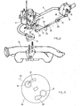
- the device shown in Figure 1 comprises a closed body 1 in the form of a cylinder. On the lateral face of the body 1 opens a connector 2 for the gas intake pipe coming from a vapor pressure regulator. From one of the bases 3 of the body 1 leaves an eccentric connection 4. The end of a flexible conduit 5 is connected to the connector 4. At the other end of the flexible conduit 5 is fixed a supply flange 6 tion with interchangeable diffuser 7. The flange 6 is clamped between the base 8 of the carburetor 9 and the manifold 10 for admitting the mixture.
- a flange 11, provided with a teardrop-shaped light 12, is integral with a pin 13 with return spring 13a and can thus rotate inside the body 1 while being applied to the inner wall of the base 3. During rotation,: .- the light 12 comes more and more in coincidence with the connector 4.
- the pin 13 crosses the base 14, opposite the base 3, and, outside the body 1, is integral in rotation from one end of a link 15, the other end of which carries a coupling ball. This loop cooperates with a ball joint 16 fixed to one end of a cable 17.
- a support 18 fixed to the body 1 carries a stopper 19 of the flexible sheath 20 of the flexible cable 17.
- the cable 17 is mounted the same way on the carburetor control drum 21 by means of a connecting rod 22, a ball joint 23, a support 24 and a sheath stopper 25, if not that this part 25 is tapped and can be screwed on a screw 26 carried by the support 24 so that the length of the cable 17 can be modified by screwing more or less the part 25 on the screw, to compensate for the games.
- the link 22 is attacked by a cable controlled by the accelerator pedal (not shown).
- Body 1 forms a stabilization chamber for the gas which arrives via the pipe 2 J whatever the distribution of the gas streams in the gas flow even at the various engine speeds whereas the vacuum can vary from minus 40 mbar to minus 650 mbar. Food is improved and made more regular. The precision of the flow adjustment can be easily improved by increasing the diameter of the flange.
- the flange 26 rotatably mounted is a disc comprising two openings 27, 28 arranged on either side of a diameter 29 so that the rotation of the flange 26 in an anticlockwise direction brings about first la.lumière 27, smaller than the light 28, overlapped with an outlet connector 30 and then brings, when the light 27 ceases to be in coincidence with the connector 30, the light 28 overlapped with a second connection 31.
Abstract
Dispositif d'alimentation du carburateur d'un moteur à combustion interne. Ce dispositif d'alimentation en gaz de pétrole liquéfié du carburateur d'un moteur à combustion interne comprend un moyen pour modifier le débit de gaz constitué d'un corps fermé (1) dans lequel un flasque (11) à lumière (12) est monté tournant de manière à amener la lumière (12) plus ou moins à recouvrement avec le raccord de sortie (4).
Description
- La présente invention concerne des dispositifs d'alimentation en carburant gazeux, notamment en gaz de pétrole liquéfié, du carburateur d'un moteur à combustion interne ayant une pédale d'accélération, comprenant des moyens, commandés par la pédale d'accélération et destinés à modifier le débit de gaz passant d'un conduit d'admission à un conduit de sortie débouchant dans le carburateur.
- Au certificat d'addition français No.74 093, on décrit un mélangeur (distributeur) à gaz pour moteurs à explosion alimentés au gaz. Le mélangeur est disposé, en aval du papillon de commande, de manière à s'adapter à l'alimentation du moteur et à s'ajouter au carburateur. Il comprend une buse de diffusion et un robinet. Le robinet comporte un boisseau commandé par la pédale d'accélération d'origine et dans lequel est ménagée une ouverture qui présente une largeur variant dans sa hauteur qui donne le gaz nécessaire à tous les régimes du moteur.
- Le réglage du débit est donné par le réglage de l'interstice compris entre le boisseau tournant et le corps du robinet. Ce réglage est peu précis, en raison de la conformation compliquée du boisseau et de l'étanchéité qui est médiocre.
- L'usinage nécessité par le robinet convient mal à la production en grande série de pièces pour véhicules automobiles dont on souhaite la reproductibilité des réglages. En outre, il n'est pas possible de réaliser simplement une alimentation compound.
- L'invention pallie ces inconvénients par un dispositif d'alimentation, dont la précision peut être améliorée pratiquement à volonté d'une manière simple, qui est étanche, qui donne une alimentation stabilisée et homogénéisée à tous les régimes du moteur et qui permet de réaliser une alimentation compound très simplement.
- Suivant l'invention, les moyens destinés à modifier le débit de gaz comprennent un corps fermé dans lequel débouchent, de part et d'autre d'un flasque à lumière de largeur variable, le conduit d'admission et le conduit de sortie, le flasque étant monté par des moyens de liaison de manière à pouvoir se déplacer d'une position où la lumière n'est pas à recouvrement avec l'un des conduits à une position où elle est à recouvrement avec ce conduit.
- La coopération d'un flasque à lumière et d'un conduit donne une réalisation plus étanche et plus précise, d'autant qu'il suffit de donner au flasque, lorsqu'il est déplacé en rotation, un rayon plus grand pour améliorer la précision. Quand le conduit recouvert par le flasque est le conduit de sortie, le corps fermé constitue une chambre de stabilisation des flux gazeux, d'autant plus efficace que les conduits d'admission et de sortie n'y débouchent pas dans le prolongement l'un de l'autre.
- Suivant une variante particulièrement avantageuse en soi, parce qu'elle supprime l'effet des vibrations et rend le montage du dispositif indépendant de la conformation du carburateur d'origine, de son emplacement et de ses raccords, l'invention vise un dispositif d'alimentation en carburant gazeux, notamment en gaz de pétrole liquéfié, du carburateur d'un moteur à combustion interne ayant une pédale d'accélération, comprenant des moyens destinés à modifier le débit de gaz allant au carburateur et des moyens de liaison desdits moyens de modification du débit à la pédale d'accélération du moteur, caractérisé en ce que lesdits moyens de modification communiquent avec le carburateur par un conduit souple et les moyens de liaison comprennent une trans-. mission souple ayant un mécanisme de réglage de leur longueur.
- Le dispositif est ainsi monté flottant et peut s'adapter à toutes les situations tant définitives dues à la conception même du moteur que temporaires provoquées par les vibrations.
- Au dessin annexé, donné uniquement à titre d'exemple :
- la figure 1 est une vue en perspective, avec arrachement, d'une partie d'un dispositif suivant l'invention,
- la figure 2 est une vue éclatée de ce dispositif, et
- la figure 3 est une vue en plan d'un flasque pour alimentation compound.
- Le dispositif représenté à la figure 1 comprend un corps fermé 1 en forme de cylindre. Sur la face latérale du corps 1 débouche un raccord 2 pour le conduit d'admission du gaz provenant d'un vapo- détendeur. De l'une des bases 3 du corps 1 part un raccord 4 excentré. L'extrémité d'un conduit souple 5 se raccorde au raccord 4. A l'autre extrémité du conduit souple 5 est fixée une bride 6 d'alimentation avec diffuseur 7 interchangeable. La bride 6 est serrée entre l'embase 8 du carburateur 9 et le collecteur 10 d'admission du mélange.
- Un flasque 11, muni d'une lumière 12 en forme de larme, est solidaire d'un tourillon 13 avec ressort de rappel 13a et peut ainsi tourner à l'intérieur du corps 1 en étant appliqué sur la paroi intérieure de la base 3. Pendant la rotation,:.- la lumière 12 vient de plus en plus en coïncidence avec le raccord 4. Le tourillon 13 traverse la base 14, opposée à la base 3, et, à l'extérieur du corps 1, est solidaire en rotation de l'une des extrémités d'une biellette 15, dont l'autre extrémité porte une boule d'attelage. Cette boucle coopère avec une rotule 16 fixée à l'une des extrémités d'un câble 17. Un support 18 fixé au corps 1 porte une pièce d'arrêt 19 de la gaine souple 20 du câble souple 17. Le câble 17 est monté de la même façon sur le tambour 21 de commande de carburateur par l'intermédiaire d'une biellette 22, d'une rotule 23 , d'un support 24 et d'une pièce d'arrêt 25 de la gaine, si ce n'est que cette pièce 25 est taraudée et peut se visser sur une vis 26 portée par le support 24 en sorte que la longueur du câble 17 peut être modifiée en vissant plus ou moins la pièce 25 sur la vis, pour compenser les jeux. La biellette 22 est attaquée par un câble commandé par la pédale d'accélération (non représentée).
- Quand on appuie sur la pédale d'accélération, on fait tourner le flasque 12 par l'intermédiaire de la transmission 15 à 26 et on amène ainsi de plus en plus la lumière 12 et le raccord à recouvrement. Quand on lâche la pédale le ressort 13a ramène la lumière 12 hors de coïncidence avec le raccord 5.
- Le corps 1 forme une chambre de stabilisation pour le gaz qui arrive par le conduit 2Jquelle que soit la répartition des veines gazeuses dans le flux gazeux même aux divers régimes du moteur alors que la dépression peut varier de moins 40 mbar à moins 650 mbar. L'alimentation s'en trouve améliorée et rendue plus régulière. La précision du réglage de débit peut être améliorée facilement en augmentant le diamètre du flasque.
- A la figure 3, le flasque 26 monté tournant est un disque comprenant deux lumières 27, 28 disposées de part et d'autre d'un diamètre 29 de manière que la rotation du flasque 26 dans le sens inverse des aiguilles d'une montre amène d'abord la.lumière 27, de plus petite hauteur que la lumière 28, à recouvrement avec un raccord 30 de sortie puis amène, quand la lumière 27 cesse d'être en coïncidence avec le raccord 30, la lumière 28 à recouvrement avec un second raccord 31. Ceci permet d'effectuer une alimentation compound.
Claims (7)
1. Dispositif d'alimentation en carburant gazeux, notamment en gaz de pétrole liquéfié, du carburateur (9) d'un moteur à combustion interne ayant une pédale d'accélération, comprenant des moyens, commandés par la pédale d'accélération destinés à modifier le débit de gaz passant d'un conduit d'admission (2) à un conduit de sortie (4) débouchant dans le carburateur (9), caractérisé en ce que les moyens comprennent un corps fermé (1) dans lequel débouchent, de part et d'autre d'un flasque (11) à lumière (12) de largeur variable, le conduit d'admission (2) et le conduit de sortie (4), le flasque (12) étant monté par des moyens de liaison de manière à pouvoir se déplacer d'une position où la lumière (12) n'est pas à recouvrement avec l'un des conduits à une position où elle est à recouvrement avec ce conduit.
2. Dispositif suivant la revendication 1, caractérisé en ce que le flasque (11) est monté tournant.
3. Dispositif suivant la revendication 1 ou 2, caractérisé en ce que le conduit à recouvrement est le conduit de sortie (4).
4. Dispositif suivant la revendication 1, 2 ou 3, caractérisé en ce que le conduit de sortie (4) n'est pas dans l'alignement du conduit d'admission (2) .
5. Dispositif suivant l'une des revendications 1 à 4, caractérisé en ce que le flasque (26) comprend deux lumières (27, 28) s'étendant de part et d'autre d'un diamètre du flasque.
6. Dispositif suivant l'une des revendications 1 à 5, caractérisé par des moyens pour relier le flasque (11) à la pédale d'accélération du moteur.
7. Dispositif d'alimentation en carburant gazeux, notamment en gaz de pétrole liquéfié, du carburateur (9) d'un moteur à combustion interne ayant une pédale d'accélération, comprenant des moyens destinés à modifier le débit de gaz allant au carburateur (9) et des moyens de liaison desdits moyens de modification du débit à la pédale d'accélération du moteur, caractérisé en ce que lesdits moyens de modification communiquent avec le carburateur par un conduit souple (5) et ces moyens de liaison comprennent une transmission (17, 20) souple ayant un mécanisme de réglage (25, 26) dans leur longueur.
Applications Claiming Priority (2)
| Application Number | Priority Date | Filing Date | Title |
|---|---|---|---|
| FR8216257A FR2533631B1 (fr) | 1982-09-24 | 1982-09-24 | Dispositif de vanne mordulente pour l'admission regulee des gaz de petrole liquides gazeifies |
| FR8216257 | 1982-09-24 |
Publications (1)
| Publication Number | Publication Date |
|---|---|
| EP0112190A1 true EP0112190A1 (fr) | 1984-06-27 |
Family
ID=9277781
Family Applications (1)
| Application Number | Title | Priority Date | Filing Date |
|---|---|---|---|
| EP83401843A Ceased EP0112190A1 (fr) | 1982-09-24 | 1983-09-21 | Dispositif d'alimentation en carburant gazeux du carburateur d'un moteur à combustion interne |
Country Status (3)
| Country | Link |
|---|---|
| EP (1) | EP0112190A1 (fr) |
| JP (1) | JPS59108856A (fr) |
| FR (1) | FR2533631B1 (fr) |
Cited By (3)
| Publication number | Priority date | Publication date | Assignee | Title |
|---|---|---|---|---|
| FR2590938A1 (fr) * | 1985-11-29 | 1987-06-05 | Primagaz Cie Gaz Petrole | Vanne, notamment pour dispositif d'alimentation du carburateur d'un moteur a combustion interne |
| DE3729336A1 (de) * | 1986-09-03 | 1988-03-31 | Nippon Denso Co | Vorrichtung zur steuerung einer brennkraftmaschine |
| WO2004020803A1 (fr) * | 2002-08-27 | 2004-03-11 | William Michael Lynch | Systeme d'alimentation en carburant pour moteur a combustion interne |
Families Citing this family (4)
| Publication number | Priority date | Publication date | Assignee | Title |
|---|---|---|---|---|
| EP0164465B1 (fr) * | 1984-06-27 | 1988-04-20 | David Tibor Szloboda | Dispostif permettant à un moteur à combustion interne à utiliser sit un combustible liquide soit un combustible gazeux |
| FR2577993B1 (fr) * | 1985-02-22 | 1989-06-16 | Totalgaz Cie Fse | Procede de regulation en continu de l'alimentation d'un moteur en carburant a l'etat gazeux et dispositif mettant en oeuvre ledit procede |
| US4637420A (en) * | 1985-12-16 | 1987-01-20 | United Technologies Corporation | Metering valve |
| DE19807503A1 (de) * | 1998-02-21 | 1999-08-26 | Bosch Gmbh Robert | Ventileinrichtung |
Citations (8)
| Publication number | Priority date | Publication date | Assignee | Title |
|---|---|---|---|---|
| US1890058A (en) * | 1929-08-26 | 1932-12-06 | Richfield Oil Company Of Calif | Gas carburetor and method of carburation |
| FR887626A (fr) * | 1942-04-10 | 1943-11-18 | Hessenwerk Rudolf Majert G M B | Dispositif d'admission de gaz pour mélangeurs de moteurs à combustion interne |
| FR1149777A (fr) * | 1956-05-15 | 1957-12-31 | Mélangeur pour moteurs à explosion alimentés au gaz | |
| US2847288A (en) * | 1956-07-30 | 1958-08-12 | William T Taylor | Carbureting means |
| US2881063A (en) * | 1956-05-07 | 1959-04-07 | Charles F Butterworth | Metering valve for carburetors and the like |
| FR74093E (fr) * | 1958-08-12 | 1960-11-07 | Mélangeur pour moteurs à explosion alimentés au gaz | |
| GB1218242A (en) * | 1968-02-17 | 1971-01-06 | Milbank & Keith Garages Ltd | Means for supplying gas to an internal combustion petrol engine as an alternative fuel |
| FR2322314A1 (fr) * | 1975-08-23 | 1977-03-25 | Itw Ltd | Robinet de reglage du chauffage d'un vehicule |
-
1982
- 1982-09-24 FR FR8216257A patent/FR2533631B1/fr not_active Expired
-
1983
- 1983-09-21 EP EP83401843A patent/EP0112190A1/fr not_active Ceased
- 1983-09-22 JP JP58174420A patent/JPS59108856A/ja active Pending
Patent Citations (8)
| Publication number | Priority date | Publication date | Assignee | Title |
|---|---|---|---|---|
| US1890058A (en) * | 1929-08-26 | 1932-12-06 | Richfield Oil Company Of Calif | Gas carburetor and method of carburation |
| FR887626A (fr) * | 1942-04-10 | 1943-11-18 | Hessenwerk Rudolf Majert G M B | Dispositif d'admission de gaz pour mélangeurs de moteurs à combustion interne |
| US2881063A (en) * | 1956-05-07 | 1959-04-07 | Charles F Butterworth | Metering valve for carburetors and the like |
| FR1149777A (fr) * | 1956-05-15 | 1957-12-31 | Mélangeur pour moteurs à explosion alimentés au gaz | |
| US2847288A (en) * | 1956-07-30 | 1958-08-12 | William T Taylor | Carbureting means |
| FR74093E (fr) * | 1958-08-12 | 1960-11-07 | Mélangeur pour moteurs à explosion alimentés au gaz | |
| GB1218242A (en) * | 1968-02-17 | 1971-01-06 | Milbank & Keith Garages Ltd | Means for supplying gas to an internal combustion petrol engine as an alternative fuel |
| FR2322314A1 (fr) * | 1975-08-23 | 1977-03-25 | Itw Ltd | Robinet de reglage du chauffage d'un vehicule |
Cited By (3)
| Publication number | Priority date | Publication date | Assignee | Title |
|---|---|---|---|---|
| FR2590938A1 (fr) * | 1985-11-29 | 1987-06-05 | Primagaz Cie Gaz Petrole | Vanne, notamment pour dispositif d'alimentation du carburateur d'un moteur a combustion interne |
| DE3729336A1 (de) * | 1986-09-03 | 1988-03-31 | Nippon Denso Co | Vorrichtung zur steuerung einer brennkraftmaschine |
| WO2004020803A1 (fr) * | 2002-08-27 | 2004-03-11 | William Michael Lynch | Systeme d'alimentation en carburant pour moteur a combustion interne |
Also Published As
| Publication number | Publication date |
|---|---|
| JPS59108856A (ja) | 1984-06-23 |
| FR2533631B1 (fr) | 1988-01-29 |
| FR2533631A1 (fr) | 1984-03-30 |
Similar Documents
| Publication | Publication Date | Title |
|---|---|---|
| EP0112190A1 (fr) | Dispositif d'alimentation en carburant gazeux du carburateur d'un moteur à combustion interne | |
| US20060125125A1 (en) | Scavenging carburetor | |
| FR2764001A1 (fr) | Carburateur pour un moteur a combustion interne | |
| EP0410871B1 (fr) | Dispositif d'étranglement à organe rotatif pour installation d'alimentation de moteur à combustion interne | |
| EP0074905B1 (fr) | Dispositif de suralimentation d'un moteur à combustion interne | |
| FR2642498A1 (fr) | Procede de montage de papillon d'etranglement sur un axe fendu | |
| FR2616873A1 (fr) | Dispositif d'ecoulement d'un fluide dans un conduit obturable par un volet ou papillon | |
| FR2496178A1 (fr) | Dispositif d'admission pour moteur a combustion interne | |
| WO1997008450A1 (fr) | Collecteur d'admission pour moteur a combustion interne | |
| CH515414A (fr) | Moteur pourvu d'un dispositif pour l'admission de deux fluides distincts dans la chambre de combustion | |
| FR2730524A1 (fr) | Carburateur pour un moteur thermique d'une machine-outil guidee manuellement | |
| FR2487434A1 (fr) | Dispositif de pompage et d'injection pour moteur a combustion interne | |
| FR2818316A1 (fr) | Dispositif de regulation du debit d'air d'une ligne d'admission d'air d'un moteur diesel | |
| EP0088678B1 (fr) | Dispositif de commande pneumatique du volet d'air d'un carburateur pour moteur à combustion interne | |
| JPH0531258Y2 (fr) | ||
| FR2492001A2 (fr) | Dispositif de formation du melange pour moteurs a combustion interne | |
| FR2648868A1 (fr) | Dispositif de commande a organe d'etranglement rotatif pour installation d'alimentation de moteur a combustion interne | |
| BE561577A (fr) | ||
| FR2606086A1 (fr) | Dispositif pour commander la rotation du papillon d'un carburateur d'un moteur lors d'une deceleration | |
| BE402566A (fr) | ||
| BE439911A (fr) | ||
| BE433532A (fr) | ||
| CH153279A (fr) | Dispositif pour faciliter le départ des moteurs à explosion. | |
| BE446597A (fr) | ||
| FR2665486A1 (fr) | Dispositif d'admission d'air pour moteur a combustion interne et procede de mise en óoeuvre. |
Legal Events
| Date | Code | Title | Description |
|---|---|---|---|
| PUAI | Public reference made under article 153(3) epc to a published international application that has entered the european phase |
Free format text: ORIGINAL CODE: 0009012 |
|
| AK | Designated contracting states |
Designated state(s): AT BE CH DE FR GB IT LI LU NL SE |
|
| 17P | Request for examination filed |
Effective date: 19840702 |
|
| RAP1 | Party data changed (applicant data changed or rights of an application transferred) |
Owner name: COMPAGNIE DES GAZ DE PETROLE PRIMAGAZ |
|
| STAA | Information on the status of an ep patent application or granted ep patent |
Free format text: STATUS: THE APPLICATION HAS BEEN REFUSED |
|
| 18R | Application refused |
Effective date: 19910205 |
|
| APAF | Appeal reference modified |
Free format text: ORIGINAL CODE: EPIDOSCREFNE |
|
| RIN1 | Information on inventor provided before grant (corrected) |
Inventor name: MOUNIER, MARC Inventor name: BOURGEON, MICHEL |