EP0109959A2 - Sensorelement zur Bestimmung des 02-Gehaltes einer Probe sowie Verfahren zur Herstellung desselben - Google Patents
Sensorelement zur Bestimmung des 02-Gehaltes einer Probe sowie Verfahren zur Herstellung desselben Download PDFInfo
- Publication number
- EP0109959A2 EP0109959A2 EP83890194A EP83890194A EP0109959A2 EP 0109959 A2 EP0109959 A2 EP 0109959A2 EP 83890194 A EP83890194 A EP 83890194A EP 83890194 A EP83890194 A EP 83890194A EP 0109959 A2 EP0109959 A2 EP 0109959A2
- Authority
- EP
- European Patent Office
- Prior art keywords
- indicator
- polymer
- sensor element
- sample
- element according
- Prior art date
- Legal status (The legal status is an assumption and is not a legal conclusion. Google has not performed a legal analysis and makes no representation as to the accuracy of the status listed.)
- Granted
Links
Images
Classifications
-
- G—PHYSICS
- G01—MEASURING; TESTING
- G01N—INVESTIGATING OR ANALYSING MATERIALS BY DETERMINING THEIR CHEMICAL OR PHYSICAL PROPERTIES
- G01N21/00—Investigating or analysing materials by the use of optical means, i.e. using sub-millimetre waves, infrared, visible or ultraviolet light
- G01N21/62—Systems in which the material investigated is excited whereby it emits light or causes a change in wavelength of the incident light
- G01N21/63—Systems in which the material investigated is excited whereby it emits light or causes a change in wavelength of the incident light optically excited
- G01N21/64—Fluorescence; Phosphorescence
- G01N21/6428—Measuring fluorescence of fluorescent products of reactions or of fluorochrome labelled reactive substances, e.g. measuring quenching effects, using measuring "optrodes"
- G01N21/643—Measuring fluorescence of fluorescent products of reactions or of fluorochrome labelled reactive substances, e.g. measuring quenching effects, using measuring "optrodes" non-biological material
-
- C—CHEMISTRY; METALLURGY
- C09—DYES; PAINTS; POLISHES; NATURAL RESINS; ADHESIVES; COMPOSITIONS NOT OTHERWISE PROVIDED FOR; APPLICATIONS OF MATERIALS NOT OTHERWISE PROVIDED FOR
- C09K—MATERIALS FOR MISCELLANEOUS APPLICATIONS, NOT PROVIDED FOR ELSEWHERE
- C09K11/00—Luminescent materials, e.g. electroluminescent or chemiluminescent
- C09K11/02—Use of particular materials as binders, particle coatings or suspension media therefor
- C09K11/025—Use of particular materials as binders, particle coatings or suspension media therefor non-luminescent particle coatings or suspension media
-
- C—CHEMISTRY; METALLURGY
- C09—DYES; PAINTS; POLISHES; NATURAL RESINS; ADHESIVES; COMPOSITIONS NOT OTHERWISE PROVIDED FOR; APPLICATIONS OF MATERIALS NOT OTHERWISE PROVIDED FOR
- C09K—MATERIALS FOR MISCELLANEOUS APPLICATIONS, NOT PROVIDED FOR ELSEWHERE
- C09K11/00—Luminescent materials, e.g. electroluminescent or chemiluminescent
- C09K11/06—Luminescent materials, e.g. electroluminescent or chemiluminescent containing organic luminescent materials
-
- G—PHYSICS
- G01—MEASURING; TESTING
- G01N—INVESTIGATING OR ANALYSING MATERIALS BY DETERMINING THEIR CHEMICAL OR PHYSICAL PROPERTIES
- G01N21/00—Investigating or analysing materials by the use of optical means, i.e. using sub-millimetre waves, infrared, visible or ultraviolet light
- G01N21/62—Systems in which the material investigated is excited whereby it emits light or causes a change in wavelength of the incident light
- G01N21/63—Systems in which the material investigated is excited whereby it emits light or causes a change in wavelength of the incident light optically excited
- G01N21/64—Fluorescence; Phosphorescence
- G01N21/645—Specially adapted constructive features of fluorimeters
- G01N21/648—Specially adapted constructive features of fluorimeters using evanescent coupling or surface plasmon coupling for the excitation of fluorescence
-
- G—PHYSICS
- G01—MEASURING; TESTING
- G01N—INVESTIGATING OR ANALYSING MATERIALS BY DETERMINING THEIR CHEMICAL OR PHYSICAL PROPERTIES
- G01N21/00—Investigating or analysing materials by the use of optical means, i.e. using sub-millimetre waves, infrared, visible or ultraviolet light
- G01N21/75—Systems in which material is subjected to a chemical reaction, the progress or the result of the reaction being investigated
- G01N21/77—Systems in which material is subjected to a chemical reaction, the progress or the result of the reaction being investigated by observing the effect on a chemical indicator
- G01N21/7703—Systems in which material is subjected to a chemical reaction, the progress or the result of the reaction being investigated by observing the effect on a chemical indicator using reagent-clad optical fibres or optical waveguides
- G01N2021/7706—Reagent provision
- G01N2021/773—Porous polymer jacket; Polymer matrix with indicator
-
- G—PHYSICS
- G01—MEASURING; TESTING
- G01N—INVESTIGATING OR ANALYSING MATERIALS BY DETERMINING THEIR CHEMICAL OR PHYSICAL PROPERTIES
- G01N21/00—Investigating or analysing materials by the use of optical means, i.e. using sub-millimetre waves, infrared, visible or ultraviolet light
- G01N21/75—Systems in which material is subjected to a chemical reaction, the progress or the result of the reaction being investigated
- G01N21/77—Systems in which material is subjected to a chemical reaction, the progress or the result of the reaction being investigated by observing the effect on a chemical indicator
- G01N2021/7769—Measurement method of reaction-produced change in sensor
- G01N2021/7786—Fluorescence
-
- G—PHYSICS
- G01—MEASURING; TESTING
- G01N—INVESTIGATING OR ANALYSING MATERIALS BY DETERMINING THEIR CHEMICAL OR PHYSICAL PROPERTIES
- G01N21/00—Investigating or analysing materials by the use of optical means, i.e. using sub-millimetre waves, infrared, visible or ultraviolet light
- G01N21/62—Systems in which the material investigated is excited whereby it emits light or causes a change in wavelength of the incident light
- G01N21/63—Systems in which the material investigated is excited whereby it emits light or causes a change in wavelength of the incident light optically excited
- G01N21/64—Fluorescence; Phosphorescence
- G01N21/6428—Measuring fluorescence of fluorescent products of reactions or of fluorochrome labelled reactive substances, e.g. measuring quenching effects, using measuring "optrodes"
-
- Y—GENERAL TAGGING OF NEW TECHNOLOGICAL DEVELOPMENTS; GENERAL TAGGING OF CROSS-SECTIONAL TECHNOLOGIES SPANNING OVER SEVERAL SECTIONS OF THE IPC; TECHNICAL SUBJECTS COVERED BY FORMER USPC CROSS-REFERENCE ART COLLECTIONS [XRACs] AND DIGESTS
- Y10—TECHNICAL SUBJECTS COVERED BY FORMER USPC
- Y10T—TECHNICAL SUBJECTS COVERED BY FORMER US CLASSIFICATION
- Y10T436/00—Chemistry: analytical and immunological testing
- Y10T436/20—Oxygen containing
- Y10T436/207497—Molecular oxygen
Definitions
- the invention relates to a sensor element for determining the 0 2 content of a sample, with an O 2 -dependent fluorescent indicator, which can be brought at least partially into contact with the sample to be measured and emits fluorescent light after excitation, the indicator substance being at least approximately homogeneously distributed in a polymer carrier is installed, and a method for producing such a sensor element.
- Molecular oxygen is known to affect the fluorescence intensity of a wide range of organic substances, for example polycyclic aromatic hydrocarbons.
- the molecular oxygen interacts with the molecule excited by the excitation light, takes energy from the molecule in the excited state and reduces the intensity of the emitted fluorescent light. It is also known to measure the partial pressure of the molecular oxygen via the detour of the fluorescence intensity of such an indicator substance.
- the fluorescent substance must be dissolved in a solvent. The partial pressure of the oxygen contained in this solvent determines the level of the fluorescent intensity.
- a thin layer is the indicator Solution on a suitable carrier material, which is translucent, and a cover of the solution of the fluorescent substance provided by a membrane permeable to oxygen.
- An illumination and light measuring device is arranged on the carrier side of this arrangement.
- the thin membrane which is permeable to oxygen, enables the oxygen partial pressure between the fluorescent layer and the adjacent medium outside of the cover membrane to be quickly compensated.
- the fluorescent layer takes on the oxygen partial pressure of the adjacent medium very quickly and then adjusts the intensity of its fluorescent light.
- the object of the invention is to improve a sensor element and a method of the type mentioned at the outset such that the disadvantages mentioned of the known devices do not occur and that, in particular, the production of an indicator built into a polymer carrier is possible in a simple manner, has sufficiently high fluorescence or fluorescence quenching.
- the carrier is formed by a cured silicone polymer in which the indicator substance is bound in solubilized form.
- a sufficiently high oxygen permeability of the membrane material is to be regarded as an essential requirement.
- the sensitivity is determined by the fluorescence decay time of the indicator used and the oxygen permeability coefficient (P 0) of the polymer material.
- silicone PO 2 ⁇ 600.10 -10 cm 2 s -1 cmHg -1
- oxygen permeability typically too small PO 2 ⁇ 35.10 -10 cm 2 s -1 cmHg -1
- the extent of the oxygen quenching in the sensor element is determined by the fluorescence decay time of the indicator and by the oxygen permeability coefficient of the polymer material (fluorescence decay time is understood as the mean lifetime of the excited state of a fluorescent molecule).
- the indicator substances can be chemically modified, namely solubilized, so that sufficiently high concentrations of the indicator substances can be dissolved in silicone.
- Solubilization (“to make it soluble”) is understood here to mean that the solubility of a substance in a (also polymeric) solvent is increased by modifying the substance (chemical modification).
- the change in the indicator substances is essentially analogous to the Friedel Crafts alkylation on aromatics, which is known per se.
- polymer or prepolymer mixtures that can be processed into membranes can now be produced with oxygen-sensitive indicator substances, the concentration of the indicator in these mixtures being so high that even in a thin layer (for example below a layer thickness of 50 ⁇ m), signal levels sufficient in terms of measurement technology can be achieved.
- the polymer mixtures are further processed into thin membranes by conventional methods. These methods can include spreading, pouring, or other methods used to coat surfaces with polymers. Another advantage of this procedure is that a thin membrane can be applied to a solid support material in an adhesive connection during the polymerization process.
- Thin polymer membranes with indicator substances of the described type fixed on supports could be used for the fluorescence-photometric measurement of oxygen in gas. It has been shown as a particular advantage of this measuring technique that response times from pure nitrogen to pure oxygen in the order of magnitude of up to 0.15 seconds could be achieved.
- optical sensors must be calibrated with calibration media of known gas concentration. If the task now is to measure the oxygen partial pressure in liquids and, furthermore, it cannot be assumed that the calibration medium has the same optical properties as the sample, optical effects are to be expected at the interface between the membrane and the sample, which the measured fluorescence signal in disturbing way. This takes place above all in that the reflection conditions at the interface between the membrane and the sample depend in each case on the optical properties of the sample medium and thus the back reflection of the excitation and fluorescent light in the sensor membrane depends on the optical properties of the sample medium. To avoid this undesirable side effect, it is necessary to give the interface between the membrane and the sample medium defined optical properties.
- the surface of the optical sensor of the measuring device can be prepared by mirroring or blackening in such a way that the influence of the optical properties of the sample medium is irrelevant.
- an additional polymer layer with low light transmission for example silicone with embedded iron oxide particles, is applied to the side of the polymer carrier facing the sample.
- these particles can be directed into a region of the indicator membrane near the surface by the action of external force fields during the hardening process of the membrane.
- force fields are: gravitational field, electric field, magnetic field.
- a further possibility for producing the optical independence from the sample medium is given according to the invention in that a thin mesh, in particular made of metal or plastic, is co-polymerized on the side of the polymer carrier facing the sample.
- the materials used for this are e.g. Screen printing nets proved to be suitable.
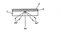
- the measures described result in a sensor element built up in layers, as shown in the figure.
- the bottom layer 1 which faces an illumination and light measuring device (not shown here) and is shone through by the excitation light (hV), serves as a solid support (for example glass).
- the middle layer 2 is the polymer layer in the molecular rer distribution contains the fluorescent indicator substance such that a fluorescence signal (hv ') dependent on the oxygen content of the sample material adjacent to the sensor element can be measured.
- the optical insulation layer 3 facing the sample material lies above the layer 2.
- the layers 2 and 3 consist of a polymer material which is well permeable to oxygen. The two layers mentioned are homogeneously bonded to one another by polymerization.
- the carrier layer 1 could possibly be dispensed with if either no mechanical stability is required or the remaining two layers are clamped in a suitable holder.
- the lighting and light measuring device is located directly adjacent to the layer 2.
- the sensor element After the vulcanization process has ended, the sensor element is ready for use.
Landscapes
- Chemical & Material Sciences (AREA)
- Health & Medical Sciences (AREA)
- Immunology (AREA)
- Organic Chemistry (AREA)
- Physics & Mathematics (AREA)
- Life Sciences & Earth Sciences (AREA)
- Materials Engineering (AREA)
- Engineering & Computer Science (AREA)
- Pathology (AREA)
- General Physics & Mathematics (AREA)
- General Health & Medical Sciences (AREA)
- Biochemistry (AREA)
- Analytical Chemistry (AREA)
- Nuclear Medicine, Radiotherapy & Molecular Imaging (AREA)
- Molecular Biology (AREA)
- Chemical Kinetics & Catalysis (AREA)
- Optics & Photonics (AREA)
- Investigating Or Analysing Materials By The Use Of Chemical Reactions (AREA)
- Investigating, Analyzing Materials By Fluorescence Or Luminescence (AREA)
- Investigating Or Analyzing Non-Biological Materials By The Use Of Chemical Means (AREA)
Abstract
Description
- Die Erfindung betrifft ein Sensorelement zur Bestimmung des 02-Gehaltes einer Probe, mit einem O2-abhängig fluoreszierenden Indikator, der mit der zu messenden Probe zumindest teilweise in Kontakt bringbar ist und nach Anregung Fluoreszenzlicht abgibt, wobei die Indikatorsubstanz zumindest annähernd homogen verteilt in einem Polymerträger eingebaut vorliegt, sowie ein Verfahren zur Herstellung eines derartigen Sensorelementes.
- Es ist bekannt, daß molekularer Sauerstoff die Fluoreszenzintensität von einer großen Reihe von organischen Substanzen, zum Beispiel der polyzyklischen aromatischen Kohlenwasserstoffe beeinflußt. Dabei tritt der molekulare Sauerstoff mit dem durch das Anregungslicht angeregten Molekül in Wechselwirkung, nimmt dabei dem im angeregten Zustand befindlichen Molekül Energie ab und reduziert die Intensität des ausgesandten Fluoreszenzlichtes. Es ist weiters bekannt, über den Umweg der Fluoreszenzintensität eines derartigen Indikatorstoffs den Partialdruck des molekularen Sauerstoffs zu messen. Dabei kann z.B. der fluoreszierende Stoff in einem Lösungsmittel gelöst sein. Der Partialdruck des in diesem Lösungsmittel enthaltenen Sausrstoffs bestimmt die Höhe der Fluoreszentintensität.
- Bei einem beispielsweise aus der DE-PS 25 08 637 bekannten Sensorelement ist eine dünne Schichte der Indikatorlösung auf einem geeigneten Trägermaterial, das lichtdurchlässig ist, und eine Abdeckung der Lösung des fluoreszierenden Stoffs durch eine für Sauerstoff permeable Membran vorgesehen. An der Trägerseite dieser Anordnung ist eine Beleuchtungs- und Lichtmeßeinrichtung angeordnet. Durch die dünne, für Sauerstoff permeable Membran, ist ein rascher Ausgleich des Sauerstoffpartialdruckes zwischen der fluoreszierenden Schichte und dem angrenzenden Medium außerhalb der Deckmembran möglich. Die fluoreszierende Schichte nimmt dabei durch Diffusion jeweils sehr rasch den Sauerstoffpartialdruck des angrenzenden Mediums an und stellt die Intensität seines Fluoreszenzlichtes darnach ein. Mit einem derartigen Sensorelement ist die Messung von Sauerstoffpartialdruck auch in wäßrigen Medien mit Hilfe optischer Mittel möglich.
- Diese Schrift offenbart auch den Gedanken, den Indikatorstoff, also die fluoreszierende Substanz, in eine polymere Folie "leckfrei" einzusiegeln. Es wird jedoch kein Verfahren zur Herstellung von Sensorelementen auf der Basis von Polymerfolien angegeben.
- Bevor nun auf die weitere Problematik des Einbaus von Indikatormolekülen in Polymere eingegangen wird, sollen die wesentlichsten aromatischen Kohlenwasserstoffverbindungen genannt werden, die als Indikator bei einem Sensorelement nach der Erfindung in Frage kommen. Von diesen wären vorzugsweise folgende Verbindungen zu nennen:
- Carbazol, Acridon, Fluoranthen, 9,10 Diphenylanthracen, Chrysen, Benz(a)anthracen, Tetracen, Pyren, Dibenz(ah)-anthracen, Perylen, Benoz(ghi)perylen, Coronen, Anthanthren, Decacyclen, 1 Aminoanthracen, 2 Aminoanthracen, 1 Aminopyren.
- über diese Verbindungen hinaus zeigen sehr viele weitere fluoreszierende Substanzen aus der Gruppe der polyzyklischen, homozyklischen oder heterozyklischen aromatischen Kohlenwasserstoffe Fluoreszenz und/bzw. Fluoreszenzlöschung durch molekularen Sauerstoff.
- Um nun eine derartige Indikatorsubstanz in ein Polymer einzubringen, kann man sich mehrerer bekannter Methoden bedienen:
- 1. Man wählt Indikatorsubstanzen, die in einem Lösungsmittel für das gewählte Polymer selbst löslich sind und bereitet eine gemeinsame Lösung des Indikatorstoffes und des Polymers, woraus durch Verdampfen des gemeinsamen Lösungsmittels der den Indikatorstoff enthaltende Polymer zurückbleibt.
- 2. Abgesehen von einem gemeinsamen Lösungsmittel kann auch ein Suspensionsmittel für ein Polymer verwendet werden, wenn dieses wiederum als Lösungsmittel für den Indikatorstoff geeignet ist.
- 3. Wenn die Polymerisation des verwendeten Polymers aus einem Reaktionsgemisch mehrerer Komponenten heraus erfolgt kann eine dieser Komponenten gleichzeitig als Lösungsmittel für den Indikatorstoff herangezogen werden.
- Nach dieser einfachen und an sich bekannten Vorgangsweise ergeben sich eine Reihe von Problemen, die dazu führen, daß in Polymere derart eingebaute Indikatormoleküle für den erfindungsgemäßen Zweck nicht geeignet sind. Dies z.B. dadurch, daß durch das Verdampfen des gmeinsamen Lösungsmittels keine molekulare Verteilung des Indikatorstoffs im Polymer entsteht, sondern daß der Indikatorstoff im Polymer auskristallisiert. Der in kristallisierter Form im Polymer vorliegende Indikatorstoff zeigt zwar durchaus Fluoreszenz, jedoch wird diese durch den anwesenden molekularen Sauerstoff nicht oder höchstens in äußerst geringem, praktisch unbrauchbarem Ausmaß beeinflußt.
- Außer einer feinen Verteilung von Mikrokristallen im Polymer wurde die Bildung von größeren Aggregaten von kristallinem Indikator im Polymer beobachtet.
- Selbst wenn in gewissen Fällen molekulare Verteilung des Indikators im Polymer vorliegt, wie dies beispielsweise mit PVC-Lösungen durchaus erreicht werden kann, zeigt sich, daß die derart eingebauten Indikatoren keine Fluoreszenzlöschung durch molekularen Sauerstoff zeigen.
- Aufgabe der Erfindung ist es, ein Sensorelement sowie ein Verfahren der eingangs genannten Art so zu verbessern, daß die genannten Nachteile der bekannten Einrichtungen nicht auftreten und daß insbesonders auf einfache Art die Herstellung eines in einem Polymerträger eingebauten Indikators ermöglicht ist, der eine meßtechnisch auswertbare, ausreichend hohe Fluoreszenz bzw. Fluoreszenzlöschung aufweist.
- Dies wird gemäß der Erfindung dadurch erreicht, daß der Träger von einem ausgehärteten Siliconpolymer gebildet ist, in dem die Indikatorsubstanz in solubilisierter Form gebunden vorliegt.
- Für die Verwendbarkeit eines Polymerträgers, beispielsweise einer Polymermembran, im Sinne der Erfindung ist ausreichend hohe Sauerstoffpermeabilität des Membranmaterials als wesentliche Voraussetzung anzusehen. Die Empfindlichkeit wird bestimmt durch die Fluoreszenzabklingzeit des verwendeten Indikators und den Säuerstoffpermeabilitätskoeffizienten (P 0 ) des Polymermaterials. Mit Ausnahme von Silicon (PO2≅600.10-10cm2s-1cmHg-1) sind die Sauerstoffpermeabilitätskoeffizienten üblicherweise zu klein (PO2<35.10-10cm2s-1cmHg-1) um meßtech- nisch brauchbare Sauerstoffempfindlichkeiten selbst bei Verwendung von Indikatoren mit hohen Fluoreszenzabklingzeiten zu erhalten. Das Ausmaß der Sauerstofflöschung im Sensorelement wird bestimmt durch die Fluoreszenzabklingzeit des Indikators und durch den Sauerstoffpermeabilitätskoeffizienten des Polymermaterials (unter Fluoreszenzabklingzeit versteht man die mittlere Lebenszeit des angeregten Zustandes eines fluoreszierenden Moleküls).
- Die Verwendung eines schlechter sauerstoffpermeablen Polymers bedingt die Verwendung von Indikatormolekülen mit großen Fluoreszenzabklingzeiten.
- Bei Verwendung des am besten sauerstoffpermeablen Polymers - Silicon - können durch den Einsatz von Indikatoren mit relativ kleinen Fluoreszenzabklingzeiten (τo>5 ns) bereits meßtechnisch verwertbare Fluoreszenzsignalunterschiede in Abhängigkeit vom Sauerstoffpartialdruck beobachtet werden.
- Aber auch für den Einbau von Indikatorstoffen in Siliconpolymeren ergab sich, daß die Konzentration der Indikatorstoffe, die durch die oben geschilderten üblichen Verfahren eingebracht werden können, für ausreichende Fluoreszenzsignalhöhe, so daß diese meßtechnisch brauchbar wird, unzureichend gering ist.
- Es hat sich jedoch überraschenderweise gezeigt, daß sich die Indikatorsubstanzen chemisch modifizieren, nämlich solubilisieren lassen, so daß ausreichend hohe Konzentrationen der Indikaotrsubstanzen in Silicon in Lösung gebracht werden können.
- Unter Solubilisierung ("löslich machen") ist hier zu verstehen, daß die Löslichkeit einer Substanz in einem (auch polymeren) Lösungsmittel durch Modifizierung der Substanz (chemische Modifizierung) erhöht wird.
- Die Veränderung an den Indikatorsubstanzen erfolgt im wesentlichen analog der an sich bekannten Friedel Crafts Alkylierung an Aromaten.
- Es hat sich damit gezeigt, daß trotz Erhöhung der Löslichkeit des fluoreszierenden Stoffs weitestgehend ungestörtes Löschverhalten vorliegt, wenn die folgenden, an sich bekannten Schritte durchgeführt werden.
-
- .) Indikator und tert. Butylchlorid werden in einem geeigneten Lösungsmittel (CS2) gelöst und unter dem katalytischen Einfluß von Aluminiumchlorid umgesetzt.
- .) Nach einem Extraktionsvorgang folgen Wasch- und Trockenprozesse; - ein Entfernen von überschüssigen organischen Lösungsmitteln durch Rotationsverdampfen führt zu einem ölartigen Rüchstand, welcher direkt als "solubilisierter Indikator" eingesetzt werden kann, oder: wie oben, aber der Indikator wird in einem Überschuß von tert. Butylchlorid ohne Zusatz eines weiteren Lösungsmittels gelöst.
- Durch diese geschilderten Maßnahmen können nun zu Membranen verarbeitbare Polymer- bzw. Praepolymergemische mit sauerstoffempfindlichen Indikatorsubstanzen hergestellt werden, wobei die Konzentration des Indikators in diesen Gemischen so hoch ist, daß auch in dünner Schicht (z:B. unterhalb von 50µ Schichtstärke) meßtechnisch ausreichende Signalhöhen erreicht werden können. Die Weiterverarbeitung der Polymergemische erfolgt durch übliche Verfahren zu dünnen Membranen. Diese Verfahren können Ausstreichen, Gießen oder andere Verfahren beinhalten, wie sie zum Beschichten von Oberflächen mit Polymeren angewandt werden. Ein weiterer Vorteil dieser Vorgangsweise ist, daß während des Polymerisationsvorganges eine dünne Membran auf einem festen Trägermaterial in haftender Verbindung aufgebracht werden kann.
- Auf Träger fixierte dünne Polymermembranen mit Indikatorsubstanzen der beschriebenen Art-konnten zur fluoreszenzphotometrischen Messung von Sauerstoff in Gas angewandt werden. Dabei hat sich als besonderer Vorteil dieser Meßtechnik gezeigt, daß man Einstellzeiten von reinem Stickstoff auf reinen Sauerstoff in der Größenordnung bis zu 0,15 sec. erreichen konnte.
- Obwohl allein das Auflösen von Indikatoren im polymeren Trägermaterial häufig ausreicht, um Indikatorverluste an die Umgebung zu verhindern, kann es für verschiedene Anwendungszwecke von Vorteil sein, andere Methoden zur Immobilisierung von Substanzen in Polymeren anzuwenden.
- Diese sind z.B.
- a) Einschränkung der Indikatorbeweglichkeit im Polymer durch chemische Modifizierung (Alkylierung mit längeren C-Ketten) der Indikatoren
- b) Kovalente Bindung der Indikatoren an die Polymersubstanz.
- Wie auch elektrochemische Sensoren für die Messung von Gasen, müssen optische Sensoren mit Eichmedien bekannter Gaskonzentration geeicht werden. Wenn nun die Aufgabe besteht, den Sauerstoffpartialdruck in Flüssigkeiten zu messen und weiters nicht davon ausgegangen werden kann, daß das Eichmedium gleiche optische Eigenschaften besitzt wie die Probe, so sind an der Grenzfläche zwischen Membran und Probe optische Effekte zu erwarten, die das gemessene Fluoreszenzsignal in störender Weise beeinflussen. Dies geschieht vor allem dadurch, daß die Reflexionsbedingungen an der Grenzfläche zwischen Membran und Probe jeweils von den optischen Eigenschaften des Probenmediums abhängen und damit die Rückreflexion des Anregungs- und Fluoreszenzlichtes in die Sensormembran von den optischen Eigenschaften des Probenmediums abhängt. Um diesen unerwünschten Nebeneffekt zu vermeiden, ist es erforderlich, der Grenzfläche zwischen Membran und Probenmedium definierte optische Eigenschaften zu verleihen.
- Es ist beispielsweise durch die DE-PS 25 08 637 bekannt, daß die Oberfläche des optischen Sensors der Meßeinrichtung durch Verspiegelung oder Schwärzung in der Weise präpariert werden kann, daß der Einfluß der optischen Eigenschaften des Probenmediums unerheblich ist.
- Bei den erfindungsgemäßen Sensorelementen mit erhöhter Indikatorkonzentration erweist sich dies als nachteilig, da eine entsprechend÷:dünne Schwärzungs- oder Versiegelungsschichte leicht von der Oberfläche des indikatorhaltigen Sensors entfernt werden kann aber zu ihrer mechanischen Stabilisierung keine erhebliche Dicke aufweisen darf, da dadurch die Diffusion von Sauerstoff aus dem Probenbereich in den Sensorinnenraum erschwert wird.
- Aus diesem Grund hat es sich in Zusammenhang mit der vorliegenden Erfindung als vorteilhaft erwiesen, wenn gemäß einer weiteren Ausgestaltung an der der Probe zugewandten Seite des Polymerträgers eine zusätzliche Polymerschicht mit geringer Lichtdurchlässigkeit, beispielsweise Silicon mit eingelagerten Eisenoxid-Partikeln, aufgebracht ist.
- Eine weitere Möglichkeit zur Herstellung der optischen Unabhängigkeit vom Probenmedium .-ist durch Einlagerung von Pigmenten wie Eisenoxidpartikeln in die indikatorhältige Polymermembran gegeben.
- Vorteilhafterweise können diese Partikeln durch Einwirkung äußerer Kraftfelder während des Härtevorganges der Membran in einen oberflächennahen Bereich der Indikatormembran dirigiert werden. (Beispiele für derartige Kraftfelder sind: Gravitationsfeld, elektrisches Feld, Magnetfeld).
- Eine weitere Möglichkeit zur Herstellung der optischen Unabhängigkeit vom Probenmedium ist gemäß der Erfindung dadurch gegeben, daß an der der Probe zugewandten Seite des Polymerträgers ein dünnes Maschengitter, insbesonders aus Metall oder Kunststoff, miteinpolymerisiert ist. Als Materialien haben sich dafür z.B. Siebdrucknetze als geeignet erwiesen.
- Durch die geschilderten Maßnahmen entsteht ein in Schichten aufgebautes Sensorelement, wie dies die Abbildung zeigt. Die unterste Schicht 1, die einer hier nicht dargestellten Beleuchtungs- und Lichtmeßeinrichtung zugewandt ist und vom Anregungslicht (hV) durchstrahlt wird, dient als fester Träger (-beispielsweise Glas). Die mittlere Schichte 2 ist jene Polymerschichte, die in molekularer Verteilung die fluoreszierende Indikatorsubstanz derart enthält, daß ein vom Sauerstoffgehalt des an das Sensorelement angrenzenden Probenmaterials abhängiges Fluoreszenzsignal (hv') meßbar ist. Über der Schichte 2 liegt die dem Probenmaterial zugewandte optische Isolationsschichte 3. Die Schichten 2 und 3 bestehen aus einem für Sauerstoff gut durchlässigen Polymermaterial. Die beiden genannten Schichten sind durch Polymerisation homogen miteinander verbunden.
- Auf die Trägerschicht 1 könnte unter Umständen verzichtet werden, wenn entweder keine mechanische Stabilität erforderlich ist, oder die verbleibenden beiden Schichten in einem geeigneten Halter aufgespannt werden. Die Beleuchtungs- und Lichtmeßeinrichtung befindet sich dabei unmittelbar an die Schichte 2 angrenzend.
- a) 0,2 g solubilisiertes (siehe Seite 5,Absatz 5 ff) Decacyclen werden in 10 g RTV-1 Silikonkautschuk (Elastosil E41, Wacker Chemie, BRD) gelöst; von der sohergestellten Lösung wird mit Hilfe einer Ausstreichvorrichtung eine Schicht in einer Stärke von etwa 20 um auf ein entfettetes Glasplättchen aufgebracht.
- Nach dem Aushärten der indikatorhältigen Siliconschicht wird ebenfalls mit Hilfe einer Ausstreichvorrichtung ein gleichmäßig verrührtes Gemisch von 10 Gewichtsteilen RTV-1 Siliconkautschuk (Elastosil E 43, Wacker Chemie, BRD) und 2 Gewichtsteilen Eisenoxidpigment in einer Schichtdicke von 20 µm auf die vulkanisierte indikatorhältige Schicht aufgetragen.
- Nach Beendigung des Vulkanisationsvorganges ist das Sensorelement einsatzbereit.
- b) Die Herstellung einer indikatorhältigen Schicht erfolgt vorerst entsprechend a).
- Nach dem Aufbringen der indikatorhältigen Siliconschicht auf den Glasträger wird diese mit einem schwarzen Siebdrucknetz (Fadendurchmesser = 30µm , offene Fläche = 46 Prozent) abgedeckt, welches auf die Siliconfläche aufgepreßt wird. Nach dem Vulkanisationsvorgang ist das Sensorelement einsatzbereit.
Claims (9)
Applications Claiming Priority (2)
| Application Number | Priority Date | Filing Date | Title |
|---|---|---|---|
| AT0426582A AT377095B (de) | 1982-11-23 | 1982-11-23 | Sensorelement zur bestimmung des o2-gehaltes einer probe sowie verfahren zur herstellung desselben |
| AT4265/82 | 1982-11-23 |
Publications (3)
| Publication Number | Publication Date |
|---|---|
| EP0109959A2 true EP0109959A2 (de) | 1984-05-30 |
| EP0109959A3 EP0109959A3 (en) | 1985-11-21 |
| EP0109959B1 EP0109959B1 (de) | 1988-03-02 |
Family
ID=3561771
Family Applications (1)
| Application Number | Title | Priority Date | Filing Date |
|---|---|---|---|
| EP83890194A Expired EP0109959B1 (de) | 1982-11-23 | 1983-10-28 | Sensorelement zur Bestimmung des 02-Gehaltes einer Probe sowie Verfahren zur Herstellung desselben |
Country Status (5)
| Country | Link |
|---|---|
| US (1) | US4657736A (de) |
| EP (1) | EP0109959B1 (de) |
| JP (1) | JPH0664046B2 (de) |
| AT (1) | AT377095B (de) |
| DE (1) | DE3375827D1 (de) |
Cited By (4)
| Publication number | Priority date | Publication date | Assignee | Title |
|---|---|---|---|---|
| AT393326B (de) * | 1988-08-02 | 1991-09-25 | Avl Verbrennungskraft Messtech | Indikatorsubstanz fuer eine messvorrichtung zur optischen bestimmung interessierender parameter einer probe und messverfahren dafuer |
| DE102004033303A1 (de) * | 2004-04-16 | 2005-11-03 | Endress + Hauser Conducta Gesellschaft für Mess- und Regeltechnik mbH + Co. KG | Vorrichtung zur Bestimmung und/oder Überwachung eines in einem fluiden Prozessmedium enthaltenen Analyten |
| WO2013181679A1 (de) * | 2012-06-06 | 2013-12-12 | Joanneum Research Forschungsgesellschaft Mbh | Opto-chemischer sensor |
| CN114755209A (zh) * | 2022-04-22 | 2022-07-15 | 杭州凯米斯物联传感科技有限公司 | 一种溶解氧传感膜头的制备方法及溶解氧传感膜头 |
Families Citing this family (60)
| Publication number | Priority date | Publication date | Assignee | Title |
|---|---|---|---|---|
| US5030420A (en) * | 1982-12-23 | 1991-07-09 | University Of Virginia Alumni Patents Foundation | Apparatus for oxygen determination |
| DE3320752A1 (de) * | 1983-06-09 | 1984-12-13 | Wolfgang Prof. Dr.Dr. 6500 Mainz Barnikol | Lumineszierende schichten zur verwendung in vorrichtungen zur bestimmung der sauerstoffkonzentration in gasen und dergleichen durch messung der lumineszensverringerung |
| AT383684B (de) * | 1984-09-17 | 1987-08-10 | Avl Verbrennungskraft Messtech | Anordnung zur fluoreszenzoptischen messung von stoffkonzentrationen in einer probe |
| EP0205232A1 (de) * | 1985-04-08 | 1986-12-17 | Kelsius, Inc. | Signalverstärkung von optischen Fasern |
| US5354825A (en) * | 1985-04-08 | 1994-10-11 | Klainer Stanley M | Surface-bound fluorescent polymers and related methods of synthesis and use |
| AT390145B (de) * | 1986-01-27 | 1990-03-26 | Avl Verbrennungskraft Messtech | Verfahren zur bestimmung der konzentration von in einer substanz enthaltenen stoffen, insbesondere von sauerstoff |
| US5019350A (en) * | 1986-02-13 | 1991-05-28 | Pfizer Hospital Products, Inc. | Fluorescent polymers |
| EP0243116A3 (de) * | 1986-04-18 | 1990-01-24 | Minnesota Mining And Manufacturing Company | Optischer Sensor |
| US5006314A (en) * | 1986-04-18 | 1991-04-09 | Minnesota Mining And Manufacturing Company | Sensor and method for sensing the concentration of a component in a medium |
| US4849172A (en) * | 1986-04-18 | 1989-07-18 | Minnesota Mining And Manufacturing Company | Optical sensor |
| ATE77483T1 (de) * | 1986-04-23 | 1992-07-15 | Avl Medical Instr Ag | Sensorelement zur bestimmung von stoffkonzentrationen. |
| US5120510A (en) * | 1986-10-10 | 1992-06-09 | Minnesota Mining And Manufacturing Company | Sensor and method for sensing the concentration of a component in a medium |
| US5462052A (en) * | 1987-01-30 | 1995-10-31 | Minnesota Mining And Manufacturing Co. | Apparatus and method for use in measuring a compositional parameter of blood |
| AT389590B (de) * | 1987-05-27 | 1989-12-27 | Avl Verbrennungskraft Messtech | Verfahren zur kontinuierlichen, quantitativen bestimmung von schwefeldioxid und anordnung zur durchfuehrung des verfahrens |
| US5043285A (en) * | 1987-07-09 | 1991-08-27 | Allied-Signal Inc. | Optical detection of oxygen |
| AT388248B (de) * | 1987-07-20 | 1989-05-26 | Avl Verbrennungskraft Messtech | Deckschicht, vorzugsweise zur probenseitigen anbringung an optischen ionensensoren |
| FR2619967A1 (fr) * | 1987-08-26 | 1989-03-03 | Micro Controle | Appareil a laser adaptable |
| US4954318A (en) * | 1987-08-31 | 1990-09-04 | Minnesota Mining And Manufacturing Company | Optical sensor |
| EP0312293A3 (de) * | 1987-10-16 | 1990-03-14 | O.C.T. Optical Chemical Technologies Limited | Fühlervorrichtung für die Analyse |
| DK163194C (da) * | 1988-12-22 | 1992-06-22 | Radiometer As | Fremgangsmaade ved fotometrisk in vitro bestemmelse af en blodgasparameter i en blodproeve |
| US4994396A (en) * | 1987-12-14 | 1991-02-19 | The Dow Chemical Company | Method for measuring the concentration or partial pressure of oxygen |
| US4818491A (en) * | 1988-03-14 | 1989-04-04 | Sun Du Jour, Inc. | Suntanning gauge |
| US5047350A (en) * | 1989-01-19 | 1991-09-10 | Eastman Kodak Company | Material and method for oxygen sensing |
| US5015715A (en) * | 1989-08-16 | 1991-05-14 | Puritan-Bennett Corporation | Method for bonding an analyte-sensitive dye compound to an addition-cure silicone |
| EP0413499A3 (en) * | 1989-08-16 | 1991-07-24 | Puritan-Bennett Corporation | Sensor element and method for making the same |
| US5182353A (en) * | 1989-08-16 | 1993-01-26 | Puritan-Bennett Corporation | Method for bonding an analyte-sensitive dye compound to an addition-cure silicone |
| US5330718A (en) * | 1989-08-16 | 1994-07-19 | Puritan-Bennett Corporation | Sensor element and method for making the same |
| US5244810A (en) * | 1990-01-12 | 1993-09-14 | Gottlieb Amos J | Analytical method |
| US5102625A (en) * | 1990-02-16 | 1992-04-07 | Boc Health Care, Inc. | Apparatus for monitoring a chemical concentration |
| US5175016A (en) * | 1990-03-20 | 1992-12-29 | Minnesota Mining And Manufacturing Company | Method for making gas sensing element |
| CA2053449A1 (en) * | 1990-10-16 | 1992-04-17 | Henry K. Hui | Optical fiber ph microsensor and method of manufacture |
| WO1992019764A1 (en) * | 1991-05-08 | 1992-11-12 | Baxter Diagnostics Inc. | Method and apparatus to detect bacterial contamination of transfusable blood |
| AT398003B (de) * | 1991-05-10 | 1994-08-25 | Avl Verbrennungskraft Messtech | Vorrichtung zur bestimmung des materieflusses |
| US5409666A (en) * | 1991-08-08 | 1995-04-25 | Minnesota Mining And Manufacturing Company | Sensors and methods for sensing |
| US5296381A (en) * | 1991-08-08 | 1994-03-22 | Minnesota Mining & Manufacturing Co. | Sensing elements and methods for making and using same |
| US5237631A (en) * | 1992-03-31 | 1993-08-17 | Moshe Gavish | Method for the manufacture of a fluorescent chemical sensor for determining the concentration of gases, vapors or dissolved gases in a sample |
| US5316949A (en) * | 1992-12-10 | 1994-05-31 | W. R. Grace & Co.-Conn. | Method of detecting the permeability of an object to oxygen |
| US5583047A (en) * | 1992-12-10 | 1996-12-10 | W. R. Grace & Co.-Conn. | Method of detecting the permeability of an object to oxygen |
| US5326531A (en) * | 1992-12-11 | 1994-07-05 | Puritan-Bennett Corporation | CO2 sensor using a hydrophilic polyurethane matrix and process for manufacturing |
| US5552272A (en) * | 1993-06-10 | 1996-09-03 | Biostar, Inc. | Detection of an analyte by fluorescence using a thin film optical device |
| US5483819A (en) * | 1994-05-27 | 1996-01-16 | W.R. Grace & Co.-Conn. | Method of detecting the permeability of an object to oxygen |
| US5670097A (en) * | 1994-12-08 | 1997-09-23 | Minnesota Mining And Manufacturing Company | Method of making blood gas sensors overcoats using permeable polymeric compositions |
| US5628310A (en) * | 1995-05-19 | 1997-05-13 | Joseph R. Lakowicz | Method and apparatus to perform trans-cutaneous analyte monitoring |
| US7335164B2 (en) | 1996-07-15 | 2008-02-26 | Ntc Technology, Inc. | Multiple function airway adapter |
| US6815211B1 (en) | 1998-08-04 | 2004-11-09 | Ntc Technology | Oxygen monitoring methods and apparatus (I) |
| US20070225612A1 (en) * | 1996-07-15 | 2007-09-27 | Mace Leslie E | Metabolic measurements system including a multiple function airway adapter |
| US6325978B1 (en) | 1998-08-04 | 2001-12-04 | Ntc Technology Inc. | Oxygen monitoring and apparatus |
| AT409306B (de) * | 1997-10-03 | 2002-07-25 | Hoffmann La Roche | Optisch chemischer sensor |
| US6794191B2 (en) | 2001-06-25 | 2004-09-21 | Photonic Systems | Process for forming polymer structures containing an oxygen sensor |
| GB0121444D0 (en) * | 2001-09-05 | 2001-10-24 | Univ Strathclyde | Sensor |
| US6642498B2 (en) | 2001-11-21 | 2003-11-04 | Agilent Technologies, Inc. | Micromirror optical multiplexer and method for directing light towards an array of sensors |
| US7402426B2 (en) * | 2002-09-20 | 2008-07-22 | Queen's University At Kingston | Detection of biological molecules by differential partitioning of enzyme substrates and products |
| US7228160B2 (en) * | 2002-11-13 | 2007-06-05 | Sorenson Medical, Inc. | System, apparatus and method for inferring glucose levels within the peritoneum with implantable sensors |
| WO2006013754A1 (ja) * | 2004-08-06 | 2006-02-09 | Powdertech Co., Ltd. | 酸素検知剤シート及びこれを用いた酸素検知剤、酸素検知剤シートの製造方法 |
| DE102005003878B3 (de) * | 2005-01-24 | 2006-07-13 | Fraunhofer-Gesellschaft zur Förderung der angewandten Forschung e.V. | Messvorrichtung zum Messen photokatalytischer Aktivität einer photokatalytischen Schicht |
| US20070243618A1 (en) * | 2006-04-11 | 2007-10-18 | Oxysense, Inc. | Device and method for non-invasive oxygen sensing of sealed packages |
| DE102010046966B4 (de) | 2010-09-29 | 2018-05-24 | Infineon Technologies Ag | Baustein und Verfahren zur Herstellung eines Bausteins |
| US20120129268A1 (en) * | 2010-11-19 | 2012-05-24 | Mayer Daniel W | Photoluminescent oxygen probe with reduced cross-sensitivity to humidity |
| WO2018055544A1 (en) * | 2016-09-21 | 2018-03-29 | Presens Precision Sensing Gmbh | Method, arrangement, computer program product and sensor foil for detecting microorganisms on a surface |
| WO2021256087A1 (ja) * | 2020-06-19 | 2021-12-23 | 三菱電機株式会社 | 環境因子検知剤 |
Family Cites Families (16)
| Publication number | Priority date | Publication date | Assignee | Title |
|---|---|---|---|---|
| US2907882A (en) * | 1957-05-03 | 1959-10-06 | Du Pont | Fluorescent screens |
| US3427273A (en) * | 1964-08-10 | 1969-02-11 | Owens Illinois Inc | Process for making luminescent organopolysiloxanes and compositions thereof |
| US3612866A (en) * | 1969-07-08 | 1971-10-12 | Brian Stevens | Instrument for determining oxygen quantities by measuring oxygen quenching of fluorescent radiation |
| JPS5123172B1 (de) * | 1971-04-22 | 1976-07-15 | ||
| CH575639A5 (en) * | 1973-04-14 | 1976-05-14 | Fluckiger & Cie | Autoluminescent device prodn - by encapsulating luminescent body in mould with reflective surfaces |
| US3881869A (en) * | 1973-07-02 | 1975-05-06 | Beckman Instruments Inc | Chemiluminescent detection of ozone |
| GB1533410A (en) * | 1974-12-20 | 1978-11-22 | Block Engineering | Antigen detecting reagents |
| DE2508637C3 (de) * | 1975-02-28 | 1979-11-22 | Max-Planck-Gesellschaft Zur Foerderung Der Wissenschaften E.V., 3400 Goettingen | Anordnung zur optischen Messung von Blutgasen |
| JPS5599070A (en) * | 1979-01-25 | 1980-07-28 | Taiyo Yuden Co Ltd | Oxygen indicator |
| JPS568547A (en) * | 1979-07-03 | 1981-01-28 | Mitsubishi Gas Chem Co Inc | Printable detecting agent |
| DE3001669A1 (de) * | 1980-01-18 | 1981-08-06 | Max-Planck-Gesellschaft zur Förderung der Wissenschaften e.V., 3400 Göttingen | Anordnung zur optischen messung von physikalischen groessen und stoffkonzentrationen |
| SU893853A1 (ru) * | 1980-04-30 | 1981-12-30 | Ленинградский Ордена Октябрьской Революции И Ордена Трудового Красного Знамени Технологический Институт Им.Ленсовета | Способ определени растворенного в воде кислорода |
| GB2085465A (en) * | 1980-10-08 | 1982-04-28 | Banyaszati Fejlesztesi Intezet | Afterglowing transparent material and a process for its manufacture |
| DE8031841U1 (de) * | 1980-11-29 | 1981-05-21 | Hoechst Ag, 6000 Frankfurt | Optischer informationstraeger aus flexibler kunststoffolie |
| DE3369801D1 (en) * | 1982-10-06 | 1987-03-19 | Avl Ag | Measurement device for determining the carbon dioxide content of a sample |
| US4526752A (en) * | 1982-12-16 | 1985-07-02 | Daniel Perlman | Oxygen indicator for packaging |
-
1982
- 1982-11-23 AT AT0426582A patent/AT377095B/de not_active IP Right Cessation
-
1983
- 1983-10-28 EP EP83890194A patent/EP0109959B1/de not_active Expired
- 1983-10-28 DE DE8383890194T patent/DE3375827D1/de not_active Expired
- 1983-11-24 JP JP58221956A patent/JPH0664046B2/ja not_active Expired - Fee Related
-
1986
- 1986-07-14 US US06/883,430 patent/US4657736A/en not_active Expired - Lifetime
Cited By (4)
| Publication number | Priority date | Publication date | Assignee | Title |
|---|---|---|---|---|
| AT393326B (de) * | 1988-08-02 | 1991-09-25 | Avl Verbrennungskraft Messtech | Indikatorsubstanz fuer eine messvorrichtung zur optischen bestimmung interessierender parameter einer probe und messverfahren dafuer |
| DE102004033303A1 (de) * | 2004-04-16 | 2005-11-03 | Endress + Hauser Conducta Gesellschaft für Mess- und Regeltechnik mbH + Co. KG | Vorrichtung zur Bestimmung und/oder Überwachung eines in einem fluiden Prozessmedium enthaltenen Analyten |
| WO2013181679A1 (de) * | 2012-06-06 | 2013-12-12 | Joanneum Research Forschungsgesellschaft Mbh | Opto-chemischer sensor |
| CN114755209A (zh) * | 2022-04-22 | 2022-07-15 | 杭州凯米斯物联传感科技有限公司 | 一种溶解氧传感膜头的制备方法及溶解氧传感膜头 |
Also Published As
| Publication number | Publication date |
|---|---|
| ATA426582A (de) | 1984-06-15 |
| EP0109959A3 (en) | 1985-11-21 |
| JPH0664046B2 (ja) | 1994-08-22 |
| AT377095B (de) | 1985-02-11 |
| DE3375827D1 (en) | 1988-04-07 |
| JPS59108958A (ja) | 1984-06-23 |
| US4657736A (en) | 1987-04-14 |
| EP0109959B1 (de) | 1988-03-02 |
Similar Documents
| Publication | Publication Date | Title |
|---|---|---|
| EP0109959B1 (de) | Sensorelement zur Bestimmung des 02-Gehaltes einer Probe sowie Verfahren zur Herstellung desselben | |
| EP0109958B1 (de) | Messeinrichtung zur Bestimmung des 02-Gehaltes einer Probe | |
| DE69432917T2 (de) | Sensorelemente und Verfahren zu ihrer Herstellung | |
| EP0105870B1 (de) | Messeinrichtung zur Bestimmung des CO2-Gehaltes einer Probe | |
| EP0829006B1 (de) | Verfahren zur herstellung eines sensitiven einschichtsystems zur messung der konzentration von analyten und ein mit diesem verfahren hergestelltes system | |
| EP0128497B1 (de) | Lumineszierende Schichten zur Verwendung in Vorrichtungen zur Bestimmung der Sauerstoffkonzentration in Gasen und dgl. durch Messung der Lumineszensverringerung | |
| DE69922776T2 (de) | Nanoteilchenstruktur zur Anwendung in einer elektronischen Anordnung, insbesondere in einem chemischen Sensor | |
| DE68912058T2 (de) | Auf chemische Stoffe ansprechende, dimensionsstabile Masse aus Organosilicon-Material und Methode. | |
| EP0016387B1 (de) | Diagnostisches Mittel zum Nachweis von Bestandteilen von Flüssigkeiten | |
| DE3346810C2 (de) | Vorrichtung zur Messung der Sauerstoffkonzentration in einem gasförmigen oder flüssigen Medium | |
| AT409306B (de) | Optisch chemischer sensor | |
| DE3343637A1 (de) | Sensorelement fuer fluoreszenzoptische messungen sowie verfahren zu seiner herstellung | |
| DE3343636A1 (de) | Sensorelement fuer fluoreszenzoptische messung sowie verfahren zu seiner herstellung | |
| AT407090B (de) | Opto-chemischer sensor sowie verfahren zu seiner herstellung | |
| DE2934405C2 (de) | Kationensensitiver Feldeffekttransistor | |
| EP0585212B1 (de) | Sensormembran eines optischen Sensors | |
| EP0578630B1 (de) | Sensormembran eines optischen Sensors zur Bestimmung eines physikalischen oder chemischen Parameters einer Probe | |
| DE69513683T2 (de) | Ionensensor und Verfahren zu dessen Herstellung | |
| AT390145B (de) | Verfahren zur bestimmung der konzentration von in einer substanz enthaltenen stoffen, insbesondere von sauerstoff | |
| DE2930074C2 (de) | Meßvorrichtung für die Bestimmung des Sauerstoffpartialdruckes in Flüssigkeiten und Gasen | |
| WO2000004367A2 (de) | Sensormembran zur bestimmung von sauerstoffkonzentrationen | |
| DE2816574C2 (de) | Fluoreszenz-Indikatoren zur Verwendung in der Chromatographie und diese enthaltende Sorptionsmittel | |
| DE3415772A1 (de) | Feuchtigkeits-sensor | |
| EP0815579B1 (de) | Black-matrix in farbbildröhren und verfahren zur herstellung der black-matrix | |
| DE10149734B4 (de) | Gassensor und Verfahren zur Herstellung seiner Polymermatrix |
Legal Events
| Date | Code | Title | Description |
|---|---|---|---|
| PUAI | Public reference made under article 153(3) epc to a published international application that has entered the european phase |
Free format text: ORIGINAL CODE: 0009012 |
|
| AK | Designated contracting states |
Designated state(s): DE FR GB |
|
| EL | Fr: translation of claims filed | ||
| PUAL | Search report despatched |
Free format text: ORIGINAL CODE: 0009013 |
|
| AK | Designated contracting states |
Designated state(s): DE FR GB |
|
| 17P | Request for examination filed |
Effective date: 19851016 |
|
| 17Q | First examination report despatched |
Effective date: 19870518 |
|
| GRAA | (expected) grant |
Free format text: ORIGINAL CODE: 0009210 |
|
| AK | Designated contracting states |
Kind code of ref document: B1 Designated state(s): DE FR GB |
|
| GBT | Gb: translation of ep patent filed (gb section 77(6)(a)/1977) | ||
| REF | Corresponds to: |
Ref document number: 3375827 Country of ref document: DE Date of ref document: 19880407 |
|
| ET | Fr: translation filed | ||
| PLBE | No opposition filed within time limit |
Free format text: ORIGINAL CODE: 0009261 |
|
| STAA | Information on the status of an ep patent application or granted ep patent |
Free format text: STATUS: NO OPPOSITION FILED WITHIN TIME LIMIT |
|
| 26N | No opposition filed | ||
| PGFP | Annual fee paid to national office [announced via postgrant information from national office to epo] |
Ref country code: GB Payment date: 19981014 Year of fee payment: 16 |
|
| PGFP | Annual fee paid to national office [announced via postgrant information from national office to epo] |
Ref country code: FR Payment date: 19981030 Year of fee payment: 16 |
|
| PGFP | Annual fee paid to national office [announced via postgrant information from national office to epo] |
Ref country code: DE Payment date: 19981211 Year of fee payment: 16 |
|
| PG25 | Lapsed in a contracting state [announced via postgrant information from national office to epo] |
Ref country code: GB Free format text: LAPSE BECAUSE OF NON-PAYMENT OF DUE FEES Effective date: 19991028 |
|
| GBPC | Gb: european patent ceased through non-payment of renewal fee |
Effective date: 19991028 |
|
| PG25 | Lapsed in a contracting state [announced via postgrant information from national office to epo] |
Ref country code: FR Free format text: LAPSE BECAUSE OF NON-PAYMENT OF DUE FEES Effective date: 20000630 |
|
| PG25 | Lapsed in a contracting state [announced via postgrant information from national office to epo] |
Ref country code: DE Free format text: LAPSE BECAUSE OF NON-PAYMENT OF DUE FEES Effective date: 20000801 |
|
| REG | Reference to a national code |
Ref country code: FR Ref legal event code: ST |