EP0108282A2 - Plattenförmiges Element für Bodenbeläge - Google Patents
Plattenförmiges Element für Bodenbeläge Download PDFInfo
- Publication number
- EP0108282A2 EP0108282A2 EP83110213A EP83110213A EP0108282A2 EP 0108282 A2 EP0108282 A2 EP 0108282A2 EP 83110213 A EP83110213 A EP 83110213A EP 83110213 A EP83110213 A EP 83110213A EP 0108282 A2 EP0108282 A2 EP 0108282A2
- Authority
- EP
- European Patent Office
- Prior art keywords
- covering material
- element according
- edge
- elements
- floor
- Prior art date
- Legal status (The legal status is an assumption and is not a legal conclusion. Google has not performed a legal analysis and makes no representation as to the accuracy of the status listed.)
- Granted
Links
Images

Classifications
-
- B—PERFORMING OPERATIONS; TRANSPORTING
- B32—LAYERED PRODUCTS
- B32B—LAYERED PRODUCTS, i.e. PRODUCTS BUILT-UP OF STRATA OF FLAT OR NON-FLAT, e.g. CELLULAR OR HONEYCOMB, FORM
- B32B3/00—Layered products comprising a layer with external or internal discontinuities or unevennesses, or a layer of non-planar shape; Layered products comprising a layer having particular features of form
- B32B3/10—Layered products comprising a layer with external or internal discontinuities or unevennesses, or a layer of non-planar shape; Layered products comprising a layer having particular features of form characterised by a discontinuous layer, i.e. formed of separate pieces of material
- B32B3/12—Layered products comprising a layer with external or internal discontinuities or unevennesses, or a layer of non-planar shape; Layered products comprising a layer having particular features of form characterised by a discontinuous layer, i.e. formed of separate pieces of material characterised by a layer of regularly- arranged cells, e.g. a honeycomb structure
-
- B—PERFORMING OPERATIONS; TRANSPORTING
- B32—LAYERED PRODUCTS
- B32B—LAYERED PRODUCTS, i.e. PRODUCTS BUILT-UP OF STRATA OF FLAT OR NON-FLAT, e.g. CELLULAR OR HONEYCOMB, FORM
- B32B27/00—Layered products comprising a layer of synthetic resin
- B32B27/12—Layered products comprising a layer of synthetic resin next to a fibrous or filamentary layer
-
- B—PERFORMING OPERATIONS; TRANSPORTING
- B32—LAYERED PRODUCTS
- B32B—LAYERED PRODUCTS, i.e. PRODUCTS BUILT-UP OF STRATA OF FLAT OR NON-FLAT, e.g. CELLULAR OR HONEYCOMB, FORM
- B32B3/00—Layered products comprising a layer with external or internal discontinuities or unevennesses, or a layer of non-planar shape; Layered products comprising a layer having particular features of form
- B32B3/02—Layered products comprising a layer with external or internal discontinuities or unevennesses, or a layer of non-planar shape; Layered products comprising a layer having particular features of form characterised by features of form at particular places, e.g. in edge regions
- B32B3/08—Layered products comprising a layer with external or internal discontinuities or unevennesses, or a layer of non-planar shape; Layered products comprising a layer having particular features of form characterised by features of form at particular places, e.g. in edge regions characterised by added members at particular parts
-
- B—PERFORMING OPERATIONS; TRANSPORTING
- B32—LAYERED PRODUCTS
- B32B—LAYERED PRODUCTS, i.e. PRODUCTS BUILT-UP OF STRATA OF FLAT OR NON-FLAT, e.g. CELLULAR OR HONEYCOMB, FORM
- B32B5/00—Layered products characterised by the non- homogeneity or physical structure, i.e. comprising a fibrous, filamentary, particulate or foam layer; Layered products characterised by having a layer differing constitutionally or physically in different parts
- B32B5/02—Layered products characterised by the non- homogeneity or physical structure, i.e. comprising a fibrous, filamentary, particulate or foam layer; Layered products characterised by having a layer differing constitutionally or physically in different parts characterised by structural features of a fibrous or filamentary layer
- B32B5/024—Woven fabric
-
- D—TEXTILES; PAPER
- D06—TREATMENT OF TEXTILES OR THE LIKE; LAUNDERING; FLEXIBLE MATERIALS NOT OTHERWISE PROVIDED FOR
- D06N—WALL, FLOOR, OR LIKE COVERING MATERIALS, e.g. LINOLEUM, OILCLOTH, ARTIFICIAL LEATHER, ROOFING FELT, CONSISTING OF A FIBROUS WEB COATED WITH A LAYER OF MACROMOLECULAR MATERIAL; FLEXIBLE SHEET MATERIAL NOT OTHERWISE PROVIDED FOR
- D06N7/00—Flexible sheet materials not otherwise provided for, e.g. textile threads, filaments, yarns or tow, glued on macromolecular material
-
- E—FIXED CONSTRUCTIONS
- E04—BUILDING
- E04F—FINISHING WORK ON BUILDINGS, e.g. STAIRS, FLOORS
- E04F15/00—Flooring
- E04F15/02—Flooring or floor layers composed of a number of similar elements
-
- B—PERFORMING OPERATIONS; TRANSPORTING
- B32—LAYERED PRODUCTS
- B32B—LAYERED PRODUCTS, i.e. PRODUCTS BUILT-UP OF STRATA OF FLAT OR NON-FLAT, e.g. CELLULAR OR HONEYCOMB, FORM
- B32B2471/00—Floor coverings
-
- Y—GENERAL TAGGING OF NEW TECHNOLOGICAL DEVELOPMENTS; GENERAL TAGGING OF CROSS-SECTIONAL TECHNOLOGIES SPANNING OVER SEVERAL SECTIONS OF THE IPC; TECHNICAL SUBJECTS COVERED BY FORMER USPC CROSS-REFERENCE ART COLLECTIONS [XRACs] AND DIGESTS
- Y10—TECHNICAL SUBJECTS COVERED BY FORMER USPC
- Y10T—TECHNICAL SUBJECTS COVERED BY FORMER US CLASSIFICATION
- Y10T428/00—Stock material or miscellaneous articles
- Y10T428/23907—Pile or nap type surface or component
- Y10T428/23979—Particular backing structure or composition
-
- Y—GENERAL TAGGING OF NEW TECHNOLOGICAL DEVELOPMENTS; GENERAL TAGGING OF CROSS-SECTIONAL TECHNOLOGIES SPANNING OVER SEVERAL SECTIONS OF THE IPC; TECHNICAL SUBJECTS COVERED BY FORMER USPC CROSS-REFERENCE ART COLLECTIONS [XRACs] AND DIGESTS
- Y10—TECHNICAL SUBJECTS COVERED BY FORMER USPC
- Y10T—TECHNICAL SUBJECTS COVERED BY FORMER US CLASSIFICATION
- Y10T428/00—Stock material or miscellaneous articles
- Y10T428/24—Structurally defined web or sheet [e.g., overall dimension, etc.]
- Y10T428/24174—Structurally defined web or sheet [e.g., overall dimension, etc.] including sheet or component perpendicular to plane of web or sheet
-
- Y—GENERAL TAGGING OF NEW TECHNOLOGICAL DEVELOPMENTS; GENERAL TAGGING OF CROSS-SECTIONAL TECHNOLOGIES SPANNING OVER SEVERAL SECTIONS OF THE IPC; TECHNICAL SUBJECTS COVERED BY FORMER USPC CROSS-REFERENCE ART COLLECTIONS [XRACs] AND DIGESTS
- Y10—TECHNICAL SUBJECTS COVERED BY FORMER USPC
- Y10T—TECHNICAL SUBJECTS COVERED BY FORMER US CLASSIFICATION
- Y10T428/00—Stock material or miscellaneous articles
- Y10T428/24—Structurally defined web or sheet [e.g., overall dimension, etc.]
- Y10T428/24479—Structurally defined web or sheet [e.g., overall dimension, etc.] including variation in thickness
- Y10T428/24496—Foamed or cellular component
- Y10T428/24504—Component comprises a polymer [e.g., rubber, etc.]
- Y10T428/24512—Polyurethane
Definitions
- the invention relates to a plate-shaped element for floor coverings with at least one lower part, which is integrally formed as a lattice work surrounded by an edge and has recesses which are formed in the edge and are provided for laying the element, and with a textile covering material on one side of the lower part is applied.
- Flooring tiles for laying in rooms or outdoors are known. These plates either consist only of a covering material which is placed directly on the floor, or of an element consisting of a lower part and a covering material which is placed on the floor, the covering material being fastened to the floor or the Elements are connected to one another by means of fastening elements.
- the aim of the invention is to provide a plate-shaped element which eliminates the stated disadvantage and can be quickly laid or folded.
- the manufacture of the plate-shaped element is characterized according to the invention in that the loading insert the material into an injection mold and then spray the lower part onto the material.
- the use of the plate-shaped element is characterized in that the elements are laid out against one another on the floor to be covered and that fastening elements are provided which can be inserted into the slots of the elements lying against one another in order to connect the elements to one another.
- the advantage of this is that the plate-shaped elements can be replaced individually without any special effort in order to replace worn or soiled elements.
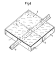
- a plate-shaped element consists of four lower parts 1 and a textile covering material 2, which is connected to one side of the lower parts 1.
- the lower parts 1 are square and are arranged such that there is a gap 12 between the adjacent lower parts 1.
- the lower part 1 is integrally formed as a lattice work 4 surrounded by an edge 3.
- the edge 3 is formed from upright sections with a rectangular cross section.
- the lattice work 3 is formed from first lattice bars 5, which have a thickness which is equal to the height of the edge 3, and from two lattice bars 6, which have a thickness which is less than the height of the edge 3.
- the lattice work 4 has a square mesh shape, the first lattice bars 5 forming a support lattice of greater width and the second lattice bars 6 forming a support lattice of smaller width.
- the second lattice bars 6 are formed with respect to the edge 3 such that a surface of the second lattice bars 6 with an edge surface of the edge 3 lie in the same plane which forms the support plane for the covering material 2.
- the latticework 4 has a square mesh shape. But it can also have a rhombic mesh shape.
- slots 7 are provided which are formed at equal intervals between the individual sections.
- the slots 7 have symmetrically shaped bulges 8 which have a round shape.
- the lower part 1 is made of plastic and can e.g. be made of polyethylene, polyvinyl chloride, polystyrene, polypropylene or polyvinyl acetate.
- the textile floor covering material can consist of a needled, tufted or woven material.
- the covering material 2 is placed in an injection mold and then the lower part 1 is sprayed on.
- the material for the lower part is pressed into the mold at a temperature of 180 ° C to 220 ° C and with a pressure of 220-400 kp / cm 2 . This creates an intensive connection between the covering material 2 and the part of the lower part 1 that comes into contact with it.
- Polypropylene, polyvinyl chloride or polystyrene is used as the injection molding material.
- the mold To prevent the fibrous material of B e- layer material 2 melts, the mold must be cooled with water.
- edge 3 As shown in FIG. 3, further recesses 9 are formed in the edge 3, which have a semicircular shape and are open on the side of the edge 3 which lies opposite the side covered with the covering material 1.
- the plate-shaped elements are laid so as to abut one another so that flooring material lies on the top.
- a ring 10 is used to connect the elements thus laid together. 3 and 4, the ring 10 has a cross section which is the same as the cross section of the slot 7.
- a bead 11 formed on the inner and outer surface of the ring 9 engages in the bulge 8 of the slot 7, thereby preventing the ring 10 from slipping out.
- holding and fixing elements can also be used, which are rectangular or oval.
- ⁇ -shaped holding members 13 are provided (Fig. L).
- the holding members 13 are placed on the floor to be covered so that the web part protrudes into the gap 12 between the lower parts 1 in order to hold the parts in position.
- the holding members 13 can be made of metal or plastic, the height of the web part being the maximum equal to the height of the edge.
Landscapes
- Engineering & Computer Science (AREA)
- Architecture (AREA)
- Textile Engineering (AREA)
- Civil Engineering (AREA)
- Structural Engineering (AREA)
- Floor Finish (AREA)
- Carpets (AREA)
Abstract
Description
- Die Erfindung betrifft ein plattenförmiges Element für Bodenbeläge mit mindestens einem Unterteil, das einstückig als ein von einem Rand umgebenes Gitterwerk ausgebildet ist und Aussparungen aufweist, die im Rand ausgebildet und zum Verlegen des Elementes vorgesehen sind, und mit einem textilen Belagmaterial, das auf einer Seite des Unterteiles aufgebracht ist.
- Bodenbelagplatten zur Verlegung in Räumen oder im Freien sind bekannt. Diese Platten bestehen entweder nur aus einem Belagmaterial, das direkt auf den Boden aufgelegt wird, oder aus einem aus einem Unterteil und einem Belagmaterial bestehenden Element, das auf den Boden aufgelegt wird, wobei das Belagmaterial auf dem Boden be- , festigt wird bzw. die Elemente mittels Befestigungselementen untereinander verbunden werden.
- Diese Beläge haben den Nachteil, dass elektrische Leitungen nicht unterhalb des Bodenbelages verlegt werden können.
- Ziel der Erfindung ist ein plattenförmiges Element zu schaffen, das den angegebenen Nachteil behebt und schnell verlegbar oder zusammenlegbar ist.
- Dieses Ziel wird erfindungsgemäss mit den kennzeichnenden Merkmalen des Patentanspruches 1 erreicht.
- Die Herstellung des plattenförmigen Elementes ist erfindungsgemäss dadurch gekennzeichnet, dass man das Belagmaterial in eine Spritzgussform einlegt und anschliessend den Unterteil auf das Belagmaterial aufspritzt.
- Die Verwendung des plattenförmigen Elementes ist erfindungsgemäss dadurch gekennzeichnet, dass die Elemente aneinanderliegend auf den zu belegenden Boden ausgelegt sind und dass Befestigungselemente vorgesehen sind, die in die Schlitze der aneinanderliegenden Elemente einsetzbar sind, um die Elemente untereinander zu verbinden.
- Als Vorteil ergibt sich daraus, dass die plattenförmigen Elemente einzeln ohne besonderen Aufwand auswechselbar sind, um abgetretene oder verschmutzte Elemente zu ersetzen.
- Im folgenden ist ein Ausführungsbeispiel des Erfindungsgegenstandes anhand der Zeichnungen näher erläutert. Es zeigen:
- Fig. 1 eine perspektive Ansicht eines Ausführungsbeispiels des erfindungsgemässen Elementes,
- Fig. 2 ein perspektivisch und auseinandergezogen dargestelltes Ausführungsbeispiel eines Teils des in Fig.l dargestellten Elementes,
- Fig. 3 ein perspektivisch dargestellter Teil eines fertiggestellten Elementes mit einem Befestigungsorgan, und
- Fig. 4 eine Seitenansicht des in Fig. 3 dargestellten Elementes aus der die Befestigung der Elemente untereinander ersichtlich ist.
- Wie Fig. 1 zeigt, besteht ein plattenförmiges Element aus vier Unterteilen 1 und einem textilen Belagmaterial 2, das mit einer Seite der Unterteile 1 verbunden ist. Die Unterteile 1 sind quadratisch ausgebildet und so angeordnet, dass zwischen den nebeneinanderliegenden Unterteilen 1 ein Spalt 12 vorhanden ist.
- Aus Fig. 2 ist ersichtlich, dass der Unterteil 1 einstückig als ein von einem Rand 3 umgebenes Gitterwerk 4 ausgebildet ist. Der Rand 3 wird aus aufrechtstehenden Abschnitten mit rechteckförmigem Querschnitt gebildet. Das Gitterwerk 3 wird aus ersten Gitterstäben 5, die eine Dicke haben die gleich der Höhe des Randes 3 ist, und aus zwei Gitterstäben 6 gebildet, die eine Dicke haben die kleiner als die Höhe des Randes 3 ist. Das Gitterwerk 4 hat eine quadratische Maschenform, wobei die ersten Gitterstäbe 5 ein Stützgitter grösserer Weite und die zweiten Gitterstäbe 6 ein Auflagegitter geringerer Weite bilden. Die zweiten Gitterstäbe 6 sind bezüglich dem Rand 3 so ausgebildet, dass eine Fläche der zweiten Gitterstäbe 6 mit einer Kantenfläche des Randes 3 in der gleichen Ebene liegen,welche die Auflageebene für das Belagmaterial 2 bildet.
- Das Gitterwerk 4 hat eine quadratische Maschenform. Es kann aber auch eine rhombische Maschenform haben.
- In den Abschnitten des Randes 3 sind Schlitze 7 vorgesehen, die in gleichen Abständen der einzelnen Abschnitte ausgebildet sind. Die Schlitze 7 weisen symmetrisch ausgebildete Ausbuchtungen 8 auf, die eine runde Form haben.
- Der Unterteil 1 besteht aus Kunststoff und kann z.B. aus Polyethylen, Polyvinylchlorid, Polystyrol, Polypropylen oder Polyvinylacetat hergestellt sein.
- Das textile Bodenbelagmaterial kann aus einem genadelten, getufteten oder gewobenen Material bestehen.
- Zur Herstellung des Elementes wird das Belagsmaterial 2 in eine Spritzgussform eingelegt und anschliessend wird der Unterteil 1 aufgespritzt.
- Das Material für den Unterteil wird mit einer Temperatur von 180°C bis 220°C und mit einem Pressdruck von 220-400 kp/cm2 in die Form gepresst. Dadurch entsteht eine intensive Verbindung zwischen dem Belagsmaterial 2 und dem mit diesem in Berührung kommenden Teil des Unterteiles 1.
- Als Spritzgussmaterial wird Polypropylen, Polyvinylchlorid oder Polystyrol verwendet.
- Um zu verhindern, dass das Fasermaterial des Be-lagmaterials 2 abschmilzt, muss die Form mit Wasser gekühlt werden.
- Wie Fig. 3 zeigt, sind im Rand 3 weitere Aussparungen 9 ausgebildet, die eine halbrunde Form aufweisen und an der Seite des Randes 3, die der mit dem Belagmaterial 1 belegten Seite gegenüberliegt, offen sind.
- Wie Fig. 4 zeigt, werden die plattenförmigen Elemente aneinanderstossend verlegt, so dass Bodenbelagmaterial an der Oberseite liegt. Um die so verlegten Elemente miteinander zu verbinden, wird ein Ring 10 verwendet. Wie aus Fig. 3 und 4 ersichtlich, hat der Ring 10 einen Querschnitt der gleich dem Querschnitt des Schlitzes 7 ist. Eine an der Innen- und Aussenfläche des Ringes 9 ausgebildete Wulst 11 greift in die Ausbuchtung 8 des Schlitzes 7 ein, wodurch ein Herausrutschen des Ringes 10 verhindert wird.
- Anstelle des Ringes 10 können auch Halte- und Fixierorgane verwendet werden, die rechteckförmig oder oval sind.
- Als Verlegungshilfe sind ┴-förmige Halteorgane 13 vorgesehen (Fig. l). Die Halteorgane 13 sind so auf den zu belegenden Boden aufgelegt, dass der Stegteil in den Spalt 12 zwischen den Unterteilen 1 hineinragt, um die Teile in Stellung zu halten. Die Halteorgane 13 können aus Metall oder Kunststoff bestehen, wobei die Höhe des Stegteiles im Maximum gleich der Höhe des Randes ist.
Claims (15)
Applications Claiming Priority (2)
| Application Number | Priority Date | Filing Date | Title |
|---|---|---|---|
| CH642282 | 1982-12-10 | ||
| CH6422/82 | 1982-12-10 |
Publications (3)
| Publication Number | Publication Date |
|---|---|
| EP0108282A2 true EP0108282A2 (de) | 1984-05-16 |
| EP0108282A3 EP0108282A3 (en) | 1987-02-25 |
| EP0108282B1 EP0108282B1 (de) | 1989-05-03 |
Family
ID=4309370
Family Applications (1)
| Application Number | Title | Priority Date | Filing Date |
|---|---|---|---|
| EP19830110213 Expired EP0108282B1 (de) | 1982-12-10 | 1983-10-13 | Plattenförmiges Element für Bodenbeläge |
Country Status (4)
| Country | Link |
|---|---|
| US (1) | US4573299A (de) |
| EP (1) | EP0108282B1 (de) |
| AT (1) | ATE42670T1 (de) |
| DE (1) | DE3379773D1 (de) |
Cited By (3)
| Publication number | Priority date | Publication date | Assignee | Title |
|---|---|---|---|---|
| EP0245375B2 (de) † | 1985-11-22 | 1993-12-01 | Cablefloor (Australia) Pty. Ltd. | Fussbodensystem |
| FR3128478A1 (fr) | 2021-10-25 | 2023-04-28 | Gerflor | Dispositif de connexion de dalles ou lames adjacentes et positionnées bord à bord d’un revêtement de sol ou mur |
| EP4446516A1 (de) | 2023-04-14 | 2024-10-16 | Gerflor | Verbesserte vorrichtung zum verbinden von aneinanderliegenden und in der kante angeordneten platten oder platten an einer boden- oder wandabdeckung |
Families Citing this family (11)
| Publication number | Priority date | Publication date | Assignee | Title |
|---|---|---|---|---|
| US6887555B2 (en) * | 2002-02-22 | 2005-05-03 | Woojin Corporation | Floor covering based on perforated PVC sheet |
| ES2325710B1 (es) * | 2007-03-29 | 2010-06-21 | Promociones Brial, S.L. | Suelo desmontable. |
| NZ566969A (en) * | 2007-03-29 | 2009-07-31 | Promociones Brial S L | Assembly system for floor and/or wall tiles |
| IL190432A (en) * | 2007-03-29 | 2012-04-30 | Promociones Brial S L | Assembly system for floor and/or wall tiles |
| US11371245B2 (en) | 2013-10-25 | 2022-06-28 | Mbrico, Llc | Tile and support structure |
| US10988931B1 (en) | 2013-10-25 | 2021-04-27 | Mbrico, Llc | Tile and support structure |
| US9151063B2 (en) | 2013-10-25 | 2015-10-06 | Mbrico, Llc | Tile and support structure |
| US11199007B2 (en) * | 2013-10-25 | 2021-12-14 | Mbrico, Llc | Tile and support structure |
| US10041254B2 (en) | 2013-10-25 | 2018-08-07 | Mbrico, Llc | Tile and support structure |
| CN106687653B (zh) * | 2014-04-24 | 2020-06-19 | 亚地斯建材有限公司 | 用于能够利用衬层元件来覆盖的面衬层结构的退耦垫 |
| US11982087B2 (en) | 2019-05-17 | 2024-05-14 | Mbrico, Llc | Tile and support structure |
Family Cites Families (15)
| Publication number | Priority date | Publication date | Assignee | Title |
|---|---|---|---|---|
| US1994644A (en) * | 1932-12-09 | 1935-03-19 | Bakelite Building Prod Co Inc | Art of building material |
| GB558076A (en) * | 1942-05-15 | 1943-12-20 | British Leyland Motor Corp | Retaining means for link pins in tracks for track-laying vehicles, and for like purposes |
| US3120083A (en) * | 1960-04-04 | 1964-02-04 | Bigelow Sanford Inc | Carpet or floor tiles |
| DE1404609A1 (de) * | 1961-03-30 | 1968-11-14 | Royal Industries | Aus Einzelstuecken zusammengesetzte elastische Matte |
| US3206351A (en) * | 1961-10-04 | 1965-09-14 | Fiberwoven Corp | Needled fabric structure and method of making same |
| US3205633A (en) * | 1963-01-03 | 1965-09-14 | Nusbaum Mortimer | Floor or like tile |
| US3295272A (en) * | 1963-08-07 | 1967-01-03 | Furukawa Casting Company Ltd | Raised floor construction |
| FR1438240A (fr) * | 1964-10-20 | 1966-05-13 | Revêtement de sols, notamment pour la pratique en plein air, ou sous abri, de jeux ou de sports | |
| GB1265625A (de) * | 1969-11-21 | 1972-03-01 | ||
| DE2432273A1 (de) * | 1974-07-05 | 1976-01-22 | Vollmann & Hoellfritsch | Boden- oder wandplatte |
| FR2294293A1 (fr) * | 1974-12-09 | 1976-07-09 | Hauserman Inc | Plancher sureleve et panneaux de construction de celui-ci |
| US4016318A (en) * | 1976-07-16 | 1977-04-05 | General Latex And Chemical Corporation | Automotive carpet mat and method of preparing same |
| DE2915622C2 (de) * | 1979-04-18 | 1984-09-27 | Fritz-Helmut 3050 Wunstorf Namendorf | Aus flexiblem Material bestehende, einen gitterförmigen Rost bildende Bodenmatte |
| FR2462515A1 (fr) * | 1979-08-01 | 1981-02-13 | Sommer Expl | Revetement de sol destine a un usage exterieur et notamment a la pratique de sports ou jeux de plein air |
| US4353947A (en) * | 1981-10-05 | 1982-10-12 | International Harvester Co. | Laminated composite structure and method of manufacture |
-
1983
- 1983-10-13 AT AT83110213T patent/ATE42670T1/de not_active IP Right Cessation
- 1983-10-13 EP EP19830110213 patent/EP0108282B1/de not_active Expired
- 1983-10-13 DE DE8383110213T patent/DE3379773D1/de not_active Expired
- 1983-11-03 US US06/548,292 patent/US4573299A/en not_active Expired - Fee Related
Cited By (4)
| Publication number | Priority date | Publication date | Assignee | Title |
|---|---|---|---|---|
| EP0245375B2 (de) † | 1985-11-22 | 1993-12-01 | Cablefloor (Australia) Pty. Ltd. | Fussbodensystem |
| FR3128478A1 (fr) | 2021-10-25 | 2023-04-28 | Gerflor | Dispositif de connexion de dalles ou lames adjacentes et positionnées bord à bord d’un revêtement de sol ou mur |
| EP4446516A1 (de) | 2023-04-14 | 2024-10-16 | Gerflor | Verbesserte vorrichtung zum verbinden von aneinanderliegenden und in der kante angeordneten platten oder platten an einer boden- oder wandabdeckung |
| FR3147821A1 (fr) | 2023-04-14 | 2024-10-18 | Gerflor | Dispositif perfectionné de connexion de dalles ou lames adjacentes et positionnées bord à bord d’un revêtement de sol ou mur |
Also Published As
| Publication number | Publication date |
|---|---|
| DE3379773D1 (en) | 1989-06-08 |
| EP0108282A3 (en) | 1987-02-25 |
| ATE42670T1 (de) | 1989-05-15 |
| US4573299A (en) | 1986-03-04 |
| EP0108282B1 (de) | 1989-05-03 |
Similar Documents
| Publication | Publication Date | Title |
|---|---|---|
| EP0477721B1 (de) | Abgehängte Kassettendecke | |
| EP1294995B1 (de) | Fussbodensystem mit mehreren gleichen Fussbodenplatten | |
| EP0108282A2 (de) | Plattenförmiges Element für Bodenbeläge | |
| DE69909145T2 (de) | Vormontageunterlage zur Herstellung einer Tüftingbürste | |
| DE2212068B2 (de) | Flächenreißverschlußhalfte | |
| DE2209100A1 (de) | Einheit für Verbindungsteppiche | |
| DE202014011061U1 (de) | Bodenplatten mit mechanischem Verriegelungssystem | |
| DE3990285C2 (de) | Matte | |
| DE102009056079A1 (de) | Kunststoff-Bodenplatte | |
| DE69000666T2 (de) | Fussbodenstruktur, insbesondere fuer mit einer computer-ausruestung versehene raeume. | |
| DE1604743A1 (de) | Befestigungsglied und Verfahren zu dessen Herstellung | |
| DE19640128A1 (de) | Bodenbelag-Element | |
| DE202022102093U1 (de) | Profilleiste | |
| DE202011051320U1 (de) | Abschalelement für den Betonbau | |
| DE102011050098A1 (de) | Paneel | |
| CH643627A5 (en) | Panel-shaped element for floor coverings | |
| DE2555767C2 (de) | Verwendung eines Gartenbausteins | |
| CH634476A5 (en) | Mat, in particular for sinks, wash basins, bath tubs, cabinets | |
| DE7907228U1 (de) | Traegermatte fuer die wasserrohre einer fussbodenheizung | |
| DE69802655T2 (de) | Kanalbodenteil für elektrische Kabelsysteme | |
| DE2264469C3 (de) | Stahlbetondecke zur Aufnahme eines Montage-FuBbodens | |
| AT331478B (de) | Losbare eckverbindung fur trennwande | |
| EP1149554B1 (de) | Fussmatte für Aussen- und Innenbereiche, insbesondere als Verbundkonstruktion für Bodenbelag | |
| DE29620106U1 (de) | Leicht erhöhte Fußbodenanordnung für das Verkabeln von Büroräumen | |
| DE202015009811U1 (de) | Bodenbelag |
Legal Events
| Date | Code | Title | Description |
|---|---|---|---|
| PUAI | Public reference made under article 153(3) epc to a published international application that has entered the european phase |
Free format text: ORIGINAL CODE: 0009012 |
|
| AK | Designated contracting states |
Designated state(s): AT BE DE FR GB IT LU NL SE |
|
| PUAL | Search report despatched |
Free format text: ORIGINAL CODE: 0009013 |
|
| AK | Designated contracting states |
Kind code of ref document: A3 Designated state(s): AT BE DE FR GB IT LU NL SE |
|
| 17P | Request for examination filed |
Effective date: 19870312 |
|
| 17Q | First examination report despatched |
Effective date: 19871007 |
|
| GRAA | (expected) grant |
Free format text: ORIGINAL CODE: 0009210 |
|
| RAP3 | Party data changed (applicant data changed or rights of an application transferred) |
Owner name: FORBO-LACHEN AG |
|
| AK | Designated contracting states |
Kind code of ref document: B1 Designated state(s): AT BE DE FR GB IT LU NL SE |
|
| ITF | It: translation for a ep patent filed | ||
| REF | Corresponds to: |
Ref document number: 42670 Country of ref document: AT Date of ref document: 19890515 Kind code of ref document: T |
|
| GBT | Gb: translation of ep patent filed (gb section 77(6)(a)/1977) | ||
| REF | Corresponds to: |
Ref document number: 3379773 Country of ref document: DE Date of ref document: 19890608 |
|
| ET | Fr: translation filed | ||
| PGFP | Annual fee paid to national office [announced via postgrant information from national office to epo] |
Ref country code: LU Payment date: 19891011 Year of fee payment: 7 |
|
| PGFP | Annual fee paid to national office [announced via postgrant information from national office to epo] |
Ref country code: FR Payment date: 19891018 Year of fee payment: 7 |
|
| PGFP | Annual fee paid to national office [announced via postgrant information from national office to epo] |
Ref country code: DE Payment date: 19891024 Year of fee payment: 7 |
|
| PGFP | Annual fee paid to national office [announced via postgrant information from national office to epo] |
Ref country code: SE Payment date: 19891030 Year of fee payment: 7 |
|
| ITTA | It: last paid annual fee | ||
| PG25 | Lapsed in a contracting state [announced via postgrant information from national office to epo] |
Ref country code: LU Free format text: LAPSE BECAUSE OF NON-PAYMENT OF DUE FEES Effective date: 19891031 |
|
| PGFP | Annual fee paid to national office [announced via postgrant information from national office to epo] |
Ref country code: NL Payment date: 19891031 Year of fee payment: 7 Ref country code: GB Payment date: 19891031 Year of fee payment: 7 Ref country code: AT Payment date: 19891031 Year of fee payment: 7 |
|
| PGFP | Annual fee paid to national office [announced via postgrant information from national office to epo] |
Ref country code: BE Payment date: 19891103 Year of fee payment: 7 |
|
| PLBE | No opposition filed within time limit |
Free format text: ORIGINAL CODE: 0009261 |
|
| STAA | Information on the status of an ep patent application or granted ep patent |
Free format text: STATUS: NO OPPOSITION FILED WITHIN TIME LIMIT |
|
| 26N | No opposition filed | ||
| PG25 | Lapsed in a contracting state [announced via postgrant information from national office to epo] |
Ref country code: GB Effective date: 19901013 Ref country code: AT Effective date: 19901013 |
|
| PG25 | Lapsed in a contracting state [announced via postgrant information from national office to epo] |
Ref country code: SE Effective date: 19901014 |
|
| PG25 | Lapsed in a contracting state [announced via postgrant information from national office to epo] |
Ref country code: BE Effective date: 19901031 |
|
| BERE | Be: lapsed |
Owner name: FORBO-LACHEN A.G. Effective date: 19901031 |
|
| PG25 | Lapsed in a contracting state [announced via postgrant information from national office to epo] |
Ref country code: NL Effective date: 19910501 |
|
| GBPC | Gb: european patent ceased through non-payment of renewal fee | ||
| NLV4 | Nl: lapsed or anulled due to non-payment of the annual fee | ||
| PG25 | Lapsed in a contracting state [announced via postgrant information from national office to epo] |
Ref country code: FR Effective date: 19910628 |
|
| PG25 | Lapsed in a contracting state [announced via postgrant information from national office to epo] |
Ref country code: DE Effective date: 19910702 |
|
| REG | Reference to a national code |
Ref country code: FR Ref legal event code: ST |
|
| EUG | Se: european patent has lapsed |
Ref document number: 83110213.2 Effective date: 19910603 |