EP0245375B2 - Fussbodensystem - Google Patents
Fussbodensystem Download PDFInfo
- Publication number
- EP0245375B2 EP0245375B2 EP86906710A EP86906710A EP0245375B2 EP 0245375 B2 EP0245375 B2 EP 0245375B2 EP 86906710 A EP86906710 A EP 86906710A EP 86906710 A EP86906710 A EP 86906710A EP 0245375 B2 EP0245375 B2 EP 0245375B2
- Authority
- EP
- European Patent Office
- Prior art keywords
- posts
- unit
- flooring
- false
- floor
- Prior art date
- Legal status (The legal status is an assumption and is not a legal conclusion. Google has not performed a legal analysis and makes no representation as to the accuracy of the status listed.)
- Expired - Lifetime
Links
- 238000009408 flooring Methods 0.000 title claims description 54
- 230000014759 maintenance of location Effects 0.000 claims description 2
- 238000010276 construction Methods 0.000 claims 1
- 230000005611 electricity Effects 0.000 abstract description 4
- 239000011159 matrix material Substances 0.000 abstract description 2
- 238000009434 installation Methods 0.000 description 8
- 239000000463 material Substances 0.000 description 7
- 239000000853 adhesive Substances 0.000 description 6
- 230000001070 adhesive effect Effects 0.000 description 6
- 239000004033 plastic Substances 0.000 description 4
- 229920003023 plastic Polymers 0.000 description 4
- 239000002023 wood Substances 0.000 description 4
- 229910052751 metal Inorganic materials 0.000 description 3
- 239000002184 metal Substances 0.000 description 3
- 229910000831 Steel Inorganic materials 0.000 description 2
- 239000004411 aluminium Substances 0.000 description 2
- 229910052782 aluminium Inorganic materials 0.000 description 2
- XAGFODPZIPBFFR-UHFFFAOYSA-N aluminium Chemical compound [Al] XAGFODPZIPBFFR-UHFFFAOYSA-N 0.000 description 2
- 238000001746 injection moulding Methods 0.000 description 2
- 238000000034 method Methods 0.000 description 2
- 238000005057 refrigeration Methods 0.000 description 2
- 239000010959 steel Substances 0.000 description 2
- 239000004412 Bulk moulding compound Substances 0.000 description 1
- 239000003677 Sheet moulding compound Substances 0.000 description 1
- HCHKCACWOHOZIP-UHFFFAOYSA-N Zinc Chemical compound [Zn] HCHKCACWOHOZIP-UHFFFAOYSA-N 0.000 description 1
- 230000002745 absorbent Effects 0.000 description 1
- 239000002250 absorbent Substances 0.000 description 1
- 238000004378 air conditioning Methods 0.000 description 1
- 238000009435 building construction Methods 0.000 description 1
- 150000001875 compounds Chemical class 0.000 description 1
- 238000004512 die casting Methods 0.000 description 1
- 238000007688 edging Methods 0.000 description 1
- 239000000945 filler Substances 0.000 description 1
- 239000011810 insulating material Substances 0.000 description 1
- 238000005304 joining Methods 0.000 description 1
- 238000004519 manufacturing process Methods 0.000 description 1
- 229910052755 nonmetal Inorganic materials 0.000 description 1
- 238000009428 plumbing Methods 0.000 description 1
- 238000000926 separation method Methods 0.000 description 1
- 230000035939 shock Effects 0.000 description 1
- 239000000243 solution Substances 0.000 description 1
- 229920001169 thermoplastic Polymers 0.000 description 1
- 229920001187 thermosetting polymer Polymers 0.000 description 1
- 239000004416 thermosoftening plastic Substances 0.000 description 1
- 125000000391 vinyl group Chemical group [H]C([*])=C([H])[H] 0.000 description 1
- 229920002554 vinyl polymer Polymers 0.000 description 1
- 239000011800 void material Substances 0.000 description 1
- XLYOFNOQVPJJNP-UHFFFAOYSA-N water Substances O XLYOFNOQVPJJNP-UHFFFAOYSA-N 0.000 description 1
- 229910052725 zinc Inorganic materials 0.000 description 1
- 239000011701 zinc Substances 0.000 description 1
Images


Classifications
-
- E—FIXED CONSTRUCTIONS
- E04—BUILDING
- E04F—FINISHING WORK ON BUILDINGS, e.g. STAIRS, FLOORS
- E04F15/00—Flooring
- E04F15/02—Flooring or floor layers composed of a number of similar elements
- E04F15/024—Sectional false floors, e.g. computer floors
- E04F15/02447—Supporting structures
-
- E—FIXED CONSTRUCTIONS
- E04—BUILDING
- E04F—FINISHING WORK ON BUILDINGS, e.g. STAIRS, FLOORS
- E04F15/00—Flooring
- E04F15/02—Flooring or floor layers composed of a number of similar elements
- E04F15/024—Sectional false floors, e.g. computer floors
- E04F15/02447—Supporting structures
- E04F15/02494—Supporting structures with a plurality of base plates or like, each base plate having a plurality of pedestals upstanding therefrom to receive the floor panels
Definitions
- This invention relates to flooring systems and more particularly to false flooring systems suitable for installation of services thereunder or therein:
- EP-A-0 108 282 corresponding to United States Patent Specification No. 4573299 entitled Floor Covering Article provides a matrix base for a false floor which includes a plate like upper surface integral with the base elements. This article requires that services first be laid down on a floor surface and then the upper surface with the integral base elements laid down to provide a false floor. Some difficulty occurs in positioning the services so that they do not interfere with the base elements and in fact these systems are particularly difficult to use.
- a false floor support unit is characterised by those features set out in the characterising portion of claim 1.
- an attachment means on the frame arrangement to enable the positioning and retention of services, cabling and duct work.
- the attachment means may for instance comprise an extension from the frame arrangement about which cable ties may be secured.
- post extension means mountable on each post, whereby to increase the length of the respective posts and hence the volume of voids produced there-between.
- the rigid arms may be positioned adjacent the base of each of the posts and extending between the bases of the post, such that the services, cabling and duct work may be laid in the voids over the arms.
- the location means to locate a section of floor may comprise a rim extending around the peripohery of the unit to define a space there-between into which a flooring panel may be received and to define the void therebelow.
- the location means may comprise a peg extending from one of the posts on each false floor support unit, the post to be received in an aperture in a flooring panel to thereby positively locate the flooring panel.
- the unit may comprise a central post, three further posts, with the four posts arranged in a first square grid arrangement, the posts being interconnected by a frame arrangement, three unit interconnecting means with the three unit interconnecting means and the central post arranged in a second square grid arrangement having a grid spacing substantially the same as the grid spacing of the first grid arrangement, the first grid arrangement being on an opposite side of the central post from the second grid arrangement, the unit interconnecting means comprising the means to interconnect the unit to adjacent units and the three unit interconnecting means joined to each other and to the central post by the frame arrangement.
- the frame arrangement may comprise rigid arms extending between adjacent posts and unit interconnecting means.
- the invention may be said to reside in a false floor arrangement comprising a plurality of false floor support units as defined above, each unit being interconnected to adjacent units by means of the connection means and a plurality of flooring panels on an upper surface of the post, the location means being received in apertures in the flooring panels to positively locate the flooring panels on the posts.
- a false flooring unit which can be used as a series of separate units on a floor with flooring panels laid over the units, with the flooring panels either being of a size to extend over two or more of the units or a size to extend only over one unit. Beneath the flooring panels is defined a space or voids, access to which may be maintained by lifting a flooring panel.
- the length of the posts may be relatively short, perhaps in the order of 20-50 millimetres but this is sufficient to provide space for services such as electricity, telephone and computer wiring to run. Where greater volume of cavity is necessary to provide for instance for gas or plumbing or air conditioning refrigeration ducting, then the post extension means as discussed above may be used to extend the posts to a total length of perhaps 100 millimetres.
- the edge may make a tray structure and hence the top of the edge may provide part of the final false floor surface when the flooring unit is fully installed or alternatively some embodiments may have a very low edge with the flooring member having a rebate to fit over the low edge so that no edges of the support unit may show between the flooring members.
- the false flooring unit according to this invention may be constructed from wood or metal or plastics material by any of the known manufacturing techniques. These may include injection moulding of thermosetting or thermoplastics materials with suitable fillers as desirable or may comprise die casting from metal such as aluminium or zinc or they may be fabricated from wood or metal. Alternatively the units may be manufactured from dough moulding compound or sheet moulding compound with suitable press arrangements to press out the desired shapes.
- the flooring panel above the unit may be made substantially from wood, or steel or plastics material as desired and may be provided with an existing grid of apertures for passing services through the panel from the floor voids to a required position or they may be of such material that holes can be drilled in any desired position.
- the flooring panels may be provided in a finished condition with a polished wood top or vinyl or any other suitable top surface or may have laid there-upon carpet squares or carpet or some alternative floor material.
- the edges of the panels may be protected by plastics edging and non-metal panels may be encased in a sheet steel or an aluminium finish.
- the false flooring units may be provided with apertures to enable fastening screws to fasten the false flooring members to an existing floor or may be adhered by any known adhesive suitable for the purpose.
- Each of the posts may be provided with some form of shock absorbent padding such as an elastomeric pad and such an elastomeric pad may assist with the taking up of any minor variations in floor level so that the resultant false floor can be made level and will be evenly based.
- shock absorbent padding such as an elastomeric pad and such an elastomeric pad may assist with the taking up of any minor variations in floor level so that the resultant false floor can be made level and will be evenly based.
- a flooring unit according to this invention may be made of any suitable dimensions and in one preferred embodiment a unit may be of a size of 600 millimetres square with a height of 48 millimetres. Alternatively a unit having a module size of 300 millimetres may be used with the unit having a thickness of 28 millimetres.
- a feature of this invention is that by having a plurality of posts to support the undersurface of each floor panel, rather than pedestals at the corners of larger and thicker panels, is that the thickness and strength of the floor panel can be reduced and economies made in the component parts of the invention.
- the posts may be spaced at 150 millimetre centres but with 50 millimetre diameter posts the unsupported distance between posts is only 80 millimetres.
- a floor panel thickness of about 18 millimetres has proved to be quite acceptable in accordance with Australian Standards for Dead and Live Loads in buildings.
- ramped flooring unit to place around the periphery of a false floor region to raise an existing floor to the height of the false floor, particularly at entrances and lift doors and the like.
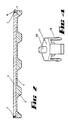
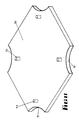
- Fig. 1 shows a first embodiment of the invention.
- Fig. 2 shows a cross-section of the embodiment shown in Fig. 1.
- Fig. 3 shows an alternative embodiment of the invention.
- Fig. 4 shows a clip and location means arrangement for the embodiment shown in Fig. 3.
- Fig. 5 shows an alternative embodiment of the false flooring support unit according to this invention.
- Fig. 6 shows an underneath view of the embodiment shown in Fig. 5.
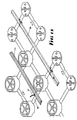
- Fig. 7 shows a perspective view of an alternative embodiment of a false flooring support unit according to this invention.
- Fig. 8 shows a connection unit suitable for Fig. 7.
- Fig. 9 shows an underneath view of the embodiment shown in Fig. 7.
- Fig. 10 shows an underneath view of the connection unit as shown in Fig. 8.
- Fig. 11 shows the underside of the cross-over plate or bridge suitable for using with the embodiments shown in Figs. 3 to 10.
- Fig. 12 shows an extension post suitable for use in the embodiments shown in Figs. 3 to 10.
- Fig. 13 shows a method of retaining services according to one embodiment of the invention.
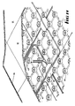
- Fig. 14 shows a general layout of a false floor using the false flooring support units according to this invention.
- FIGs. 1 and 2 Now looking more closely at the various embodiments, a first embodiment is shown in Figs. 1 and 2.
- the false floor support unit is substantially rectangular and includes a rectangular frame 1, having a raised edge 2, into which a flooring panel 3 (shown broken away) is placed.
- the flooring panel 3 sits on a framework 4 which is supported by a plurality of legs or posts 5.
- the false floor support units of this embodiment may be connected to adjacent false floor support units by means of plugs 6 on the rectangular framework extending into sockets 7 on adjacent units.
- Cabling or services such as telephones may be installed underneath the framework 4 to travel along in the cavities formed between a floor and the unit and where it is desired to extend the service into an office space or work space above the floor, suitable apertures may be drilled in the floor panel 3.
- Fig. 2 shows a cross-sectional view of the embodiment shown in Figure 1 and the size of the cavities formed under the unit may be more easily seen in this view.
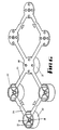
- FIG. 3 A further embodiment of the false floor support unit is shown in Figs. 3 and 4.
- the false floor support unit comprises a central post 10, having a series of arms 11 extending therefrom to half posts 12, with further rigid arms 13 extending to quarter posts 14 at the corners of a square false floor support unit.
- the false floor support unit according to this embodiment is used the way up that it is shown in this embodiment, so that the rigid arms 11 and 13 go nearest the floor so that cables and other services are able to be laid over the arms.
- a flooring panel is laid over the false floor support unit to rest onto the posts 10, 12 and 14.
- Adjacent false floor units are connected together by means of a bracket 15 extending from two of the half posts received in recess 16 on a half post of an adjacent false floor support unit.
- a corner joining fastener 17 as shown in Fig. 4 which includes four downwardly depending catch arms 18, which engage into the recesses 19 of four adjacent quarter posts 14 of four adjacent false floor support units when placed together.
- This fastener 17 provides corner connection for the false floor support units and also by means of the spigot or peg 20, which extends above the planar surface of the top of posts enables a flooring panel to be positively engaged so that it will not move around on the false floor support unit.
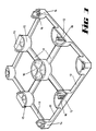
- a single false floor support unit includes a central post 21 and three further posts 22.
- the central post and the three further posts 22 are held in a square grid arrangement by means of rigid arms 23 extending from the central post 21 and rigid arms 24 around the periphery of the square grid arrangement.
- the arms 23 and 24 are semi-circular in cross-section so that once the false floor support unit is laid down and a flooring unit placed over, then cables being pushed or slid under the floor will not engage or be caught up on the arms.
- one of the further posts 22 includes a spigot or peg 25 to engage into an aperture in a floor panel when placed on the false floor support unit.
- the post interconnection means 26 include a planar plate having extending therefrom four engagement clips 29.
- the post engagement means 26 fit within the further posts 22 of the adjacent floor support units with the diameter of the post interconnection means being such as to just fit in the internal diameter of the further posts 22, with the engagement clips 29 engaging over the rim 30 of boss 31 underneath the three further posts 22. It will be noted that the arms 28 fit into recesses 33 in the underside edges of the posts 22.
- attachment means comprising an extension 34, extending from one side of the arm 28 for instance with recesses 35, 36 and 37 formed adjacent the extension 34.
- a cable tie to fasten cables to the framework may be passed under the extension 34 to extend out of the recesses 35 or 36 or if a cable is to be laid diagonally, to extend either from the recess 35 or 36 to the recess 37.
- apertures 38 are provided in the base of the post interconnection plates 26 and also in the base of the central post 21. If the false floor support unit is to be laid onto a wooden floor then suitable screw fastening meamu may be provided to fasten the false floor support unit to the floor. Alternatively on any floor surface adhesive may be placed underneath the plates 26 and the central posts 21 and when the unit is placed onto the floor, adhesive may ooze through the apertures 38to provide, when the adhesive has set, better adhesive fastening which will in turn provide mechanical as well as adhesive fastening.
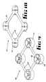
- Figs. 7, 8, 9 and 10 show an alternative embodiment of the false floor support unit according to this invention.
- a first part of the unit 40 as shown in Fig. 7 includes four posts 41 spaced apart in a square grid arrangement by means of rigid arms 42 with one of the posts 41 including a spigot 43 for engaging a floor panel.
- the other part of the floor support unit shown in Fig. 8 comprises an interconnection unit 44, comprising four interconnection plates 45 spaced apart by rigid arms 46.
- a similar connection arrangement by the use of engagement clips 47 on the plates 45 engaging over the rim 48 of spigot 49 on the underneath of the posts 41 to the embodiment shown in Fig. 5 is provided.
- Fig. 11 shows a cross-over plate or bridge for the embodiments of the false floor support unit shown in Figs. 3 to 10.
- the cross-over plate 50 has recesses 51 in each corner which positively locate the cross-over plate within the square defined by four adjacent posts and the legs 52 provide a space underneath the plate in which cables may be passed in one direction and over the plate cables may be passed in a transverse direction.
- the plate is used the other way up than that is shown in Fig. 11.
- Fig. 12 shows an extension post 53 which may be placed onto the top of any of the posts shown in the embodiments in Figs. 3 to 10 so that the cavity under the false floor may be increased where necessary.
- a spigot or peg 54 may be provided on the top of the extension post 53 to enable engagement of floor panels.
- Fig. 13 shows how cables 55 and 56 may be tied by means of ties 57 to the frame arms 58 and it will be noted that with the spacing of attachment means as shown in Figs. 5 and 6 the cables may be fastened on alternate arms which will give good rigid fastening.
- Fig. 14 shows an overall view of a false floor arrangement as provided by the false floor support units of the present invention.
- the plurality of posts 60 support floor panels 61 which are of greater area than just one of the false floor support units and cables 62 and 63 for instance can be laid in any direction underneath the floor panels 61. Where cables cross, the cross-over plate or bridge 50 may be used to provide an insulated cross-over between the cables of different services. Carpet 64 or any other suitable floor covering may be placed over the panels 61 to provide a good finish for the false floor.
- the false flooring support unit according to this invention is particularly adapted to be manufactured from injection moulding of plastics material or other suitable compound.
Landscapes
- Engineering & Computer Science (AREA)
- Architecture (AREA)
- General Engineering & Computer Science (AREA)
- Civil Engineering (AREA)
- Structural Engineering (AREA)
- Floor Finish (AREA)
- Installation Of Indoor Wiring (AREA)
Claims (9)
- Unterlage für einen Blindfußboden, die eine Vielzahl von Pfostenelementen (5,10,12,14,21,22,41) gleicher Länge, die senkrecht zu einer gemeinsamen Ebene angeordnet sind und sich von dieser aus erstrecken, wobei die Pfostenelemente mit einem quadratischen, dreieckigen oder hexagonalen Gittermuster angeordnet sind und durch ein Rahmenwerk starrer Arme (11,23,24,27,28,42), die sich zwischen benachbarten Pfosten in dem Gittermuster erstrecken, verbunden und mit einem Abstand versehen sind und mindestens ein Positionierelement (2,29,25,43,54) auf mindestens einem Pfosten aufweist, um den Bodenbelag (3,61) formschlüssig auf der Unterlage zu fixieren, dadurch gekennzeichnet, daß die Unterlage die Pfostenelemente, die starren Arme und das Positionierelement umfasst, die als Baueinheit ausgebildet sind und daß die so gebildete Unterlageeinheit auch Verbindungselemente (6,7,15,16,17,26,44) zum Verrasten der Unterlageeinheit aufweist.
- Blindfußbodenunterlageeinheit nach Anspruch 1, die ferner Befestigungselemente (34,35,36,37) am Rahmenwerk (24,28) enthält, um die Befestigung von Verbindungselementen (57) für das Zusammenhalten von Bereitstellungseinrichtungen, Verkabelung und von verlegten Kanälen (55,56) zu ermöglichen.
- Blindfußbodenunterlageeinheit nach Anspruch 1 oder 2, die ferner an jedem Pfostenelement (10,12,14,21,22,41) anbringbare Pfostenverlängerungselemente (53) enthält, wodurch die Länge der jeweiligen Pfostenelemente und damit das Volumen der zwischen ihnen erzeugten Hohlräume vergrößert wird.
- Blindfußbodenunterlageeinheit nach einem der vorhergehenden Ansprüchen, wobei die starren Arme (11,23,24,27,28,42,46) benachbart der Basis der Pfostenelemente (10,12,14,21,22,41) angeordnet sind.
- Blindfußbodenunterlageeinheit nach einem der vorhergehenden Ansprüche, wobei das Positionierelement zum Fixieren eines Bereichs des Fußbodenbelags einen Rand (2) aufweist, der sich am Umfang der Einheit entlang erstreckt, um dazwischen einen Bereich zu definieren, in dem ein Fußbodenbelagselement (3) aufgenommen werden kann und um darunter die Hohlräume zu definieren.
- Blindfußbodenunterlageeinheit nach einem der vorhergehenden Ansprüche, wobei das Positionierelement einen Stöpsel oder einen Führungszapfen (20,25,43,54) aufweist, der sich von einem der Pfostenelemente (14,22,41) aus erstreckt und in einer Aussparung in einem Fußbodenbelagselement aufgenommen wird, um dadurch das Element formschlüssig zu fixieren.
- Blindfußbodenunterlageeinheit nach einem der vorhergehenden Ansprüche, wobei die Einheit einen Mittelpfosten (21), drei weitere Pfostenelemente (22), wobei die vier Pfostenelemente in einem ersten Quadratgittermuster angeordnet sind, und drei Einrastelemente (26) aufweist, wobei die drei Einrastelemente und der Mittelpfosten in einem zweiten Quadratgittermuster angeordnet sind, dessen Gitterweite im wesentlichen dem ersten Quadratgittermuster entspricht, wobei sich das erste Gittermuster auf einer dem zweiten Gittermuster gegenüberliegenden Seite des Mittelpfosten befindet, wobei die Einrastvorrichtung das Verbindungselement (29) zum Verrasten der Einheit mit benachbarten Einheiten und den drei miteinander und durch das Rahmenwerk (27,28) mit dem Mittelpfosten verbundenen Einrastelementen umfasst.
- Blindfußbodenunterlageeinheit nach Anspruch 7, wobei das Rahmenwerk (27,28) starre Arme umfasst, die sich zwischen benachbarten Pfosten und dem Einrastelement erstrecken.
- Blindfußbodenanordnung mit einer Vielzahl von Blindfußbodenunterlageeinheiten nach einem der Ansprüche 1 bis 8, wobei jede Einheit mit benachbarten Einheiten über Verbindungselemente (6,7,15,16,17,26) und eine Vielzahl von auf einer oberen Fläche der Pfostenelemente befindlichen Fußbodenbelagselementen verrastet ist, wobei die Positionierelemente in Aussparungen in den Fußbodenbelagselementen eingreifen, um die Fußbodenbelagselemente formschlüssig auf den Pfostenelementen zu fixieren.
Applications Claiming Priority (3)
| Application Number | Priority Date | Filing Date | Title |
|---|---|---|---|
| AU3536/85 | 1985-11-22 | ||
| AUPH353685 | 1985-11-22 | ||
| PCT/AU1986/000334 WO1987003324A1 (en) | 1985-11-22 | 1986-10-31 | Flooring system |
Publications (4)
| Publication Number | Publication Date |
|---|---|
| EP0245375A1 EP0245375A1 (de) | 1987-11-19 |
| EP0245375A4 EP0245375A4 (de) | 1988-03-21 |
| EP0245375B1 EP0245375B1 (de) | 1991-01-30 |
| EP0245375B2 true EP0245375B2 (de) | 1993-12-01 |
Family
ID=3771384
Family Applications (1)
| Application Number | Title | Priority Date | Filing Date |
|---|---|---|---|
| EP86906710A Expired - Lifetime EP0245375B2 (de) | 1985-11-22 | 1986-10-31 | Fussbodensystem |
Country Status (7)
| Country | Link |
|---|---|
| EP (1) | EP0245375B2 (de) |
| JP (1) | JPH0826656B2 (de) |
| CA (1) | CA1279968C (de) |
| DE (1) | DE3677377D1 (de) |
| NZ (1) | NZ218236A (de) |
| WO (1) | WO1987003324A1 (de) |
| ZA (1) | ZA868683B (de) |
Families Citing this family (21)
| Publication number | Priority date | Publication date | Assignee | Title |
|---|---|---|---|---|
| DE3628772A1 (de) * | 1986-08-25 | 1988-03-03 | Kloeber Fa Hans | Anordnung an doppelboeden |
| JPH0660524B2 (ja) * | 1986-12-16 | 1994-08-10 | インフィル・システムズ・ベスローテン・ベンノートシャップ | 床構造および間仕切りし配線・配管を配設する方法 |
| AU2550088A (en) * | 1987-10-05 | 1989-04-18 | John G. Brown | Modular-accessible-units |
| DE3801765A1 (de) * | 1988-01-22 | 1989-07-27 | Hubertus C Starp | Distanzkoerper |
| CA2001808C (en) * | 1988-10-31 | 1993-03-30 | Fumio Takeda | Interior panel unit for permitting arrangement of cables and devices on room floor |
| USRE35369E (en) * | 1989-02-03 | 1996-11-05 | Guilford (Delaware) Inc. | Flooring system especially designed for facilities which house data processing equipment |
| DE3904236A1 (de) * | 1989-02-13 | 1990-08-16 | Rheinhold & Mahla Gmbh | Hohlraum-montage-boden |
| US5499476A (en) * | 1993-08-31 | 1996-03-19 | Interface, Inc. | Low profile raised panel flooring with metal support structure |
| USRE39097E1 (en) | 1994-03-25 | 2006-05-23 | Guildford (Delaware), Inc. | Metal support framework for low profile raised panel flooring |
| US5675950A (en) * | 1994-03-25 | 1997-10-14 | Guilford (Delaware), Inc. | Metal support framework for low profile raised panel flooring |
| US5713168A (en) * | 1994-03-25 | 1998-02-03 | Guilford (Delaware), Inc. | Junction box for low profile raised panel flooring |
| AUPP392898A0 (en) * | 1998-06-05 | 1998-07-02 | Ribaric, Anthony | Multi-web construction |
| CN2414128Y (zh) * | 2000-04-11 | 2001-01-10 | 朱寿会 | 一种防静电网络化地板 |
| FR2827890B1 (fr) * | 2001-07-26 | 2004-10-01 | Patrice Elluin | Procede de realisation d'un plancher sureleve, et plancher sureleve susceptible d'etre realise par ce procede |
| DE102005019638B4 (de) * | 2005-04-26 | 2007-02-08 | Kronotec Ag | Verfahren zur Herstellung eines Fußbodenelementes |
| ES2332301B1 (es) * | 2009-05-29 | 2010-09-13 | Industrias Tomas Morcillo S.L. | Suelo tecnico ligero. |
| US8950141B2 (en) | 2012-09-12 | 2015-02-10 | Schluter Systems L.P. | Veneer underlayment |
| WO2018077563A1 (de) * | 2016-10-25 | 2018-05-03 | Schlueter Werner | Bodenplatte und system zur herstellung eines hohlraumbodens |
| DE202017101349U1 (de) | 2017-03-09 | 2018-06-12 | Werner Schlüter | Entkopplungsmatte |
| IT202100010508A1 (it) * | 2021-04-26 | 2022-10-26 | Geoplast Spa | Sistema di elementi modulari per la realizzazione di solai nervati sopraelevati e/o aerati |
| WO2025224570A1 (en) * | 2024-04-22 | 2025-10-30 | Dakota Group S.A.S. Di Zeno Cipriani & C. | Support structure of raised floors |
Citations (5)
| Publication number | Priority date | Publication date | Assignee | Title |
|---|---|---|---|---|
| US277554A (en) † | 1883-05-15 | de abreu | ||
| DE1784235B1 (de) † | 1968-07-20 | 1972-05-25 | Willi Schreiber | Wand- oder Fussbodenbelagsplatte als vorgefertigte Installationsplatte mit Grund- und Deckplatte und aus mehreren solcher Platten zusammengesetzter beheizbarer oder kuehlbarer Fussboden- oder Wandbelag |
| AU484603B2 (en) † | 1974-07-25 | 1976-01-29 | Liskey Architectural Systems Inc. | Improvements in or relating to floor assemblies |
| DE2742429A1 (de) † | 1977-09-21 | 1979-03-29 | Artus Feist | Montageplatte fuer heiz- und kuehlmittelschlaeuche und deren verwendung |
| EP0108282A2 (de) † | 1982-11-04 | 1984-05-16 | Forbo-Lachen AG | Plattenförmiges Element für Bodenbeläge |
Family Cites Families (7)
| Publication number | Priority date | Publication date | Assignee | Title |
|---|---|---|---|---|
| CH277554A (fr) * | 1945-10-11 | 1951-09-15 | Yovanovitch Lazare | Couverture d'un bâtiment à terrasse. |
| US2929529A (en) * | 1956-01-26 | 1960-03-22 | Nat Supply Co | Terrazzo holder for under-floor junction box |
| GB1425977A (en) * | 1972-08-07 | 1976-02-25 | Tate Architectural Products | Floor panel and elevated floor assembly using same |
| SU590419A1 (ru) * | 1975-08-26 | 1978-01-30 | Центральный научно-исследовательский и проектно-экспериментальный институт промышленных зданий и сооружений | Секционный пол |
| DE2900759C3 (de) * | 1979-01-10 | 1986-05-07 | Marbeton Kies- U. Betonwerk Marstetten Gmbh, 7971 Aitrach | Aufgeständerter Boden |
| SU903523A1 (ru) * | 1979-09-14 | 1982-02-07 | Предприятие П/Я Г-4743 | Секционный п о л |
| JPS61102962A (ja) * | 1984-10-25 | 1986-05-21 | 松下電工株式会社 | ボツクス付床パネル |
-
1986
- 1986-10-31 EP EP86906710A patent/EP0245375B2/de not_active Expired - Lifetime
- 1986-10-31 DE DE8686906710T patent/DE3677377D1/de not_active Expired - Lifetime
- 1986-10-31 JP JP61505991A patent/JPH0826656B2/ja not_active Expired - Fee Related
- 1986-10-31 WO PCT/AU1986/000334 patent/WO1987003324A1/en not_active Ceased
- 1986-11-10 NZ NZ218236A patent/NZ218236A/xx unknown
- 1986-11-17 ZA ZA868683A patent/ZA868683B/xx unknown
- 1986-11-19 CA CA000523393A patent/CA1279968C/en not_active Expired - Lifetime
Patent Citations (6)
| Publication number | Priority date | Publication date | Assignee | Title |
|---|---|---|---|---|
| US277554A (en) † | 1883-05-15 | de abreu | ||
| DE1784235B1 (de) † | 1968-07-20 | 1972-05-25 | Willi Schreiber | Wand- oder Fussbodenbelagsplatte als vorgefertigte Installationsplatte mit Grund- und Deckplatte und aus mehreren solcher Platten zusammengesetzter beheizbarer oder kuehlbarer Fussboden- oder Wandbelag |
| AU484603B2 (en) † | 1974-07-25 | 1976-01-29 | Liskey Architectural Systems Inc. | Improvements in or relating to floor assemblies |
| DE2742429A1 (de) † | 1977-09-21 | 1979-03-29 | Artus Feist | Montageplatte fuer heiz- und kuehlmittelschlaeuche und deren verwendung |
| EP0108282A2 (de) † | 1982-11-04 | 1984-05-16 | Forbo-Lachen AG | Plattenförmiges Element für Bodenbeläge |
| US4573299A (en) † | 1982-12-10 | 1986-03-04 | Forbo-Teppichwerk Ag | Floor covering article |
Also Published As
| Publication number | Publication date |
|---|---|
| EP0245375A4 (de) | 1988-03-21 |
| NZ218236A (en) | 1990-01-29 |
| CA1279968C (en) | 1991-02-12 |
| EP0245375A1 (de) | 1987-11-19 |
| JPS63502125A (ja) | 1988-08-18 |
| JPH0826656B2 (ja) | 1996-03-13 |
| DE3677377D1 (de) | 1991-03-07 |
| WO1987003324A1 (en) | 1987-06-04 |
| EP0245375B1 (de) | 1991-01-30 |
| ZA868683B (en) | 1987-06-24 |
Similar Documents
| Publication | Publication Date | Title |
|---|---|---|
| EP0245375B2 (de) | Fussbodensystem | |
| US4905437A (en) | Flooring system and method of providing | |
| US4883503A (en) | Access floor construction | |
| US4996810A (en) | Access flooring | |
| US4858401A (en) | Cable ducting system | |
| US2867301A (en) | False flooring system | |
| US5057647A (en) | Low rise flooring structure | |
| US4438610A (en) | Clamped access floor panel assembly | |
| US6079177A (en) | Removable ceiling panel assembly | |
| US7975443B2 (en) | Precast prestress raised access floor construction | |
| USRE47329E1 (en) | Anchor and alignment device for floor covering tiles | |
| AU604604B2 (en) | Improvements in flooring systems | |
| JP2000220279A (ja) | 床構造体 | |
| JPH0412200Y2 (de) | ||
| JPH0436350Y2 (de) | ||
| JPH09296592A (ja) | 床構造及び床施工方法 | |
| JPH071373Y2 (ja) | 二重床用間仕切り係止金具 | |
| JPH0248582Y2 (de) | ||
| JP3400688B2 (ja) | 乾式二重床構造および間取り変更方法 | |
| JPH054509Y2 (de) | ||
| KR100605273B1 (ko) | 이중바닥재의 바닥재지지모듈 및 바닥재지지모듈을 이용한바닥재 설치방법 | |
| JP2514051Y2 (ja) | 床構造 | |
| JPH0960264A (ja) | フリーアクセスフロア用基本パネル | |
| CN115434547A (zh) | 一种方形水池的直边底座调节结构 | |
| JPH0578787U (ja) | フロアー |
Legal Events
| Date | Code | Title | Description |
|---|---|---|---|
| PUAI | Public reference made under article 153(3) epc to a published international application that has entered the european phase |
Free format text: ORIGINAL CODE: 0009012 |
|
| AK | Designated contracting states |
Kind code of ref document: A1 Designated state(s): DE FR GB IT |
|
| 17P | Request for examination filed |
Effective date: 19871203 |
|
| A4 | Supplementary search report drawn up and despatched |
Effective date: 19880321 |
|
| 17Q | First examination report despatched |
Effective date: 19890628 |
|
| GRAA | (expected) grant |
Free format text: ORIGINAL CODE: 0009210 |
|
| AK | Designated contracting states |
Kind code of ref document: B1 Designated state(s): DE FR GB IT |
|
| REF | Corresponds to: |
Ref document number: 3677377 Country of ref document: DE Date of ref document: 19910307 |
|
| ITF | It: translation for a ep patent filed | ||
| ET | Fr: translation filed | ||
| PLBI | Opposition filed |
Free format text: ORIGINAL CODE: 0009260 |
|
| 26 | Opposition filed |
Opponent name: MAHLE GMBH Effective date: 19910920 |
|
| PUAH | Patent maintained in amended form |
Free format text: ORIGINAL CODE: 0009272 |
|
| STAA | Information on the status of an ep patent application or granted ep patent |
Free format text: STATUS: PATENT MAINTAINED AS AMENDED |
|
| ITF | It: translation for a ep patent filed | ||
| 27A | Patent maintained in amended form |
Effective date: 19931201 |
|
| AK | Designated contracting states |
Kind code of ref document: B2 Designated state(s): DE FR GB IT |
|
| ET3 | Fr: translation filed ** decision concerning opposition | ||
| REG | Reference to a national code |
Ref country code: GB Ref legal event code: IF02 |
|
| PGFP | Annual fee paid to national office [announced via postgrant information from national office to epo] |
Ref country code: GB Payment date: 20031029 Year of fee payment: 18 |
|
| PGFP | Annual fee paid to national office [announced via postgrant information from national office to epo] |
Ref country code: FR Payment date: 20031110 Year of fee payment: 18 |
|
| PGFP | Annual fee paid to national office [announced via postgrant information from national office to epo] |
Ref country code: DE Payment date: 20031113 Year of fee payment: 18 |
|
| PG25 | Lapsed in a contracting state [announced via postgrant information from national office to epo] |
Ref country code: GB Free format text: LAPSE BECAUSE OF NON-PAYMENT OF DUE FEES Effective date: 20041031 |
|
| PG25 | Lapsed in a contracting state [announced via postgrant information from national office to epo] |
Ref country code: DE Free format text: LAPSE BECAUSE OF NON-PAYMENT OF DUE FEES Effective date: 20050503 |
|
| GBPC | Gb: european patent ceased through non-payment of renewal fee |
Effective date: 20041031 |
|
| PG25 | Lapsed in a contracting state [announced via postgrant information from national office to epo] |
Ref country code: FR Free format text: LAPSE BECAUSE OF NON-PAYMENT OF DUE FEES Effective date: 20050630 |
|
| REG | Reference to a national code |
Ref country code: FR Ref legal event code: ST |
|
| PG25 | Lapsed in a contracting state [announced via postgrant information from national office to epo] |
Ref country code: IT Free format text: LAPSE BECAUSE OF NON-PAYMENT OF DUE FEES Effective date: 20051031 |