EP0106806A1 - Verfahren zur Herstellung eines äusseren Uhrenteiles und durch dieses Verfahren hergestelltes Teil - Google Patents
Verfahren zur Herstellung eines äusseren Uhrenteiles und durch dieses Verfahren hergestelltes Teil Download PDFInfo
- Publication number
- EP0106806A1 EP0106806A1 EP19830810467 EP83810467A EP0106806A1 EP 0106806 A1 EP0106806 A1 EP 0106806A1 EP 19830810467 EP19830810467 EP 19830810467 EP 83810467 A EP83810467 A EP 83810467A EP 0106806 A1 EP0106806 A1 EP 0106806A1
- Authority
- EP
- European Patent Office
- Prior art keywords
- matrix
- growth
- metal
- parts
- metallic
- Prior art date
- Legal status (The legal status is an assumption and is not a legal conclusion. Google has not performed a legal analysis and makes no representation as to the accuracy of the status listed.)
- Withdrawn
Links
Images


Classifications
-
- G—PHYSICS
- G04—HOROLOGY
- G04B—MECHANICALLY-DRIVEN CLOCKS OR WATCHES; MECHANICAL PARTS OF CLOCKS OR WATCHES IN GENERAL; TIME PIECES USING THE POSITION OF THE SUN, MOON OR STARS
- G04B37/00—Cases
- G04B37/22—Materials or processes of manufacturing pocket watch or wrist watch cases
-
- G—PHYSICS
- G04—HOROLOGY
- G04B—MECHANICALLY-DRIVEN CLOCKS OR WATCHES; MECHANICAL PARTS OF CLOCKS OR WATCHES IN GENERAL; TIME PIECES USING THE POSITION OF THE SUN, MOON OR STARS
- G04B19/00—Indicating the time by visual means
- G04B19/06—Dials
- G04B19/12—Selection of materials for dials or graduations markings
-
- G—PHYSICS
- G04—HOROLOGY
- G04B—MECHANICALLY-DRIVEN CLOCKS OR WATCHES; MECHANICAL PARTS OF CLOCKS OR WATCHES IN GENERAL; TIME PIECES USING THE POSITION OF THE SUN, MOON OR STARS
- G04B39/00—Watch crystals; Fastening or sealing of crystals; Clock glasses
- G04B39/02—Sealing crystals or glasses
-
- G—PHYSICS
- G04—HOROLOGY
- G04D—APPARATUS OR TOOLS SPECIALLY DESIGNED FOR MAKING OR MAINTAINING CLOCKS OR WATCHES
- G04D3/00—Watchmakers' or watch-repairers' machines or tools for working materials
- G04D3/0069—Watchmakers' or watch-repairers' machines or tools for working materials for working with non-mechanical means, e.g. chemical, electrochemical, metallising, vapourising; with electron beams, laser beams
Definitions
- the present invention relates mainly to a method for manufacturing timepiece clothing components under improved productivity conditions.
- These components can be composite, i.e. formed of a first part made of a non-metallic material which is difficult to machine and of one or more second parts which are metallic and which are permanently linked to the first part.
- Electroforming is a method of forming metal parts which is already known and which has been used for pieces of jewelry and timepieces. It is a process that derives directly from plating, as indicated, for example, in Swiss patent no. 530 472. It has been found that it is possible to deposit metallic layers of a precious or other metal, having a relatively large thickness on a metallic or non-metallic substrate but previously coated with a metallization layer. Even in the case where the substrate itself has a generally concave shape, the coating can form in a galvanic bath by electrolytic means.
- this part has, in its external surface which was previously in contact with the substrate, a shape which reproduces in an extremely true to the appearance of the initial surface of the substrate.
- Swiss patent CH 507 542 it was known to use this method with non-precious metals with the aim of constituting forms for the molding of clock faces and, according to the Swiss patent CE 601 500, electroforming could be used for make small decorative pieces such as reported time signs for example.
- the patents CH 387 787 and CH 332 904 describe the manufacture of composite components of the clothing of wristwatches.
- the object of the present invention is to eliminate this defect entirely and, consequently, to allow obtaining, by growth in a galvanic or chemical bath, massive metal parts having practically any thickness, in particular thicknesses exceeding very largely 1 mm, without the surface irregularities generally observed with the electroforming process disturbing the appearance of the clothing.
- the various operations which are applied successively to achieve the desired result include in particular an operation for forming a metal layer by depositing particles in the gaseous phase, an operation including several forms of implementation are well known.
- the form of implementation of the method which will be described in relation to FIGS. 1 to 5, therefore relates to the manufacture of a watch crystal provided on its reverse with a metal ring allowing the watertight mounting of this crystal on the middle-bezel of a wristwatch of the classic piece type.
- the glass 1 is visible in particular in FIG. 1. It is a mineral glass or sapphire crystal and for the implementation of the process, we will begin by making this crystal by giving it its final shape and appearance according to current and known methods.
- a metal coating 3 is formed on the periphery of the rear face 2 of the glass 1.
- the formation of this metallized peripheral strip comprises the 'deposit by evaporation under vacuum of a thin metallic layer over the entire surface 2 of the glass.
- This metal layer having to serve as a bonding layer between the support ring of the glass and the glass itself, it should have sufficient adhesion and for this it is given a thickness which ensures that the desired result is obtained. Tests have shown, for example, that this layer could have a thickness of 0.2 to 0.5 microns.
- the metal deposited on the glass will for example be gold or silver or, if appropriate, nickel, etc.
- the periphery of this layer is spared by depositing on it a non-metallic coating such as for example a suitable lacquer and the coating is removed on the entire surface. central area which is not protected by the lague. Then, in a dissolution bath, the lacquer is removed in order to obtain the glass 1, coated in its peripheral zone with the metallized layer.
- a non-metallic coating such as for example a suitable lacquer
- the second operation of the method consists in incorporating the glass 1 into a matrix which has an imprint 4, giving exactly the shape and the dimensions which the second part of the component must have, that is to say the ring intended to serve as its support.
- this matrix consists of a plastic sidewall 5 which is glued to the surface 2, so as to slightly cover the inner limit of the metallized layer 3 and of a lining 6, also made of plastic material which can itself be formed from several pieces and which covers the upper surface of the glass with the same edge and the outer zone of the surface 2.
- the imprint delimited by the matrix 5-6 has the shape of an annular groove, the bottom of which is formed by a part of the metal covering 3, while the two parallel and opposite sides consist of the edge of the blank 5 and the edge of the matrix element 6.
- FIG. 2 illustrates the third operation of the method, operation during which all of the surfaces of the imprint 4 are coated with a metallic layer.
- the deposition of this metallic layer can also be carried out by vacuum evaporation.
- the metal which will be deposited will then preferably be copper, because what is essential is to make the surface of the imprint conductive in order to favor the growth by electrolytic deposition of the body which will fill the imprint 4.
- the copper coating 7 extends not only on the internal faces of the imprint, but also, as seen in 7a, has at least one conductive strip going towards the outside so that it can be connected to one of the poles of the current source.
- this second metallization operation could, if necessary, be eliminated.
- it could also alternatively and according to the shape that should be given to the imprint 4, do without the first metallization operation. In this case, it should be ensured that the metallized layer intended to conduct the current also has sufficient adhesion to the non-metallic part so that the connection between the metallic body formed by growth and the non-metallic part is sufficient in order to the intended application.
- FIG. 3 illustrates the following operation for forming the support piece permanently attached to the back of the glass 1.
- the matrix consisting of the pieces 1, 5 and 6 is suspended in a galvanic bath, the tab 7a being connected to one of the poles of the current source so that the coating 7 forms one of the electrodes.
- the metal of the electrolyte is then deposited in the cavity 4 and a metal coating 8 gradually increases on all the parts which are coated with the metallic layer 7. As can be seen in FIG. 3, this coating fills little about the footprint 4.
- the growth rate of the deposit is not the same in all the points of the footprint. It tends to be weaker at the location of interior angles and, on the contrary, to be stronger at the location of exterior angles.
- this imprint is an annular groove like that which is represented in FIGS. 1 to 3, the width of this groove should be at least equal to its height.
- the body which forms in the matrix presents on the faces of the imprint a surface state which reproduces in an extremely faithful way. surface condition of the imprint, so that these surfaces then do not require any termination operation provided that the surfaces of the imprint are themselves finished surfaces.
- the duration of the growth operation depends on many factors. It can reach several hours when it comes to making, for example, a metal ring whose profile measures between 1 x 1 and 2 x 2 millimeters.
- FIG. 4 illustrates the following operation which consists in machining the reverse of the matrix and of the metallic body formed in the impression, in order to give it its final dimensions.
- the elements 5 and 6 of the matrix as well as the deposit metal 8 were machined on a lathe so as to form the flat rear surface 9, which extends parallel to the rear surface 2 and the crystal 1.
- the ring 8, whose profile is approximately square, is linked to the reverse of the glass 1 by adhesion to its surface 2. so that it constitutes a support element allowing then the mounting of the glass on a watch case.
- FIG. 5 also shows the bottom 14 of the case which is fixed inside the middle part of the bezel by conventional means and known per se, with the interposition of a seal 15.
- component 1-8 the manufacture of which has just been described, can also be obtained in all kinds of different embodiments and variants.
- the ring 8 could, if necessary, extend to the periphery of the glass.
- the plan shape of the ring 8 and of the crystal 1 it is understood that many shapes can be produced.
- the glass 1 can be a circular or oval glass, or of any other shape and likewise the ring 8 can either follow the outside contour of the glass, or on the contrary extend along a different contour.
- auxiliary parts which are fixed to the reverse of the glass on the metallized layer 3 and which, during the assembly of the matrix, as illustrated in FIG. 1, come to protrude inside the cavity 4.
- These auxiliary parts can be fixed, for example by gluing on the metal covering 3 or, if necessary, be engaged in openings made beforehand through the glass 1. During the growth of the body 8, the latter gradually drowns the auxiliary part or parts to which we have just alluded.
- This variant of the method described in relation to FIGS. 1 to 5 aims to improve the adhesion of the body 8.
- the metal part which must be permanently linked to the non-metallic part to form a clothing component
- Fig. 6 illustrates an embodiment of the process in which the clothing component that is obtained consists of a crystal 16 made of mineral glass, or of sapphire, or of any other transparent non-metallic material and of a metallic bezel 17.
- the glass 16 does not have a cylindrical edge but, in this case, its edge is cut in a bevel along the surface 18 for a reason which will be explained later. It should also be noted that it is on this bevelled surface 18 that the metal layer 19 intended to ensure the connection between the two parts 16 and 17 of the component is deposited.
- the matrix intended to allow the formation of the body 17 by growth, is here also composed of two plastic elements in the form of rings.
- the ring 20 is bonded to the lower surface 21 of the glass 16 and its outer periphery extends up to the edge which separates the frustoconical surface 18 from the lower planar face 21.
- This ring 20 will for example be glued to the surface 21 and the same will apply to the part 22 which forms the other part of the matrix and which covers the external peripheral zone of the upper surface of the glass 16 while delimiting, with the edge of the ring 20, the annular impression 23 which is limited by the surfaces 24 of the piece of plastic material 22 by the bevel 18 of the glass 16 and by the edge 25 of the ring 20.
- the matrix consisting of parts 20, 16 and 22, is suspended, as in the first embodiment, in a galvanic bath, the metallized layers 24, 18 and 25 being connected to one of the poles of the source of current.
- the metal coating 17 whose thickness, although irregular increases with the duration of the treatment.
- the plastic parts of the matrix that is to say the parts 20 and 22 are removed by dissolution in a suitable solvent and the result of this operation is a monolithic component consisting of the glass 16 and the body 17 which, as can be seen, plays the role of a lens support lens.
- This bezel is tightly, permanently and rigidly bonded to the glass.
- the visible external surfaces of this bezel immediately present a smooth and polished surface state if the surfaces of the components of the matrix already present this state. so they can be used without further termination processing.
- This bezel 17 can be fixed for example to notch or by engagement in a middle part. It is understood that the lower surface which has irregularities due to the galvanic growth operation is masked in the complete box since this surface is turned towards the side of the box body.
- the glass 16 may also have a usual appearance, that is to say with a cylindrical edge.
- the outer periphery of the reverse 21 of the crystal as well as the edge would be the surfaces which should be metallized in order to achieve their adhesion with the body 17 and the latter would exhibit a notch like a notch ice. It would adhere to the glass on its edge and on the periphery of its underside.
- the body 17 can, after elimination of the matrix, undergo a metallization operation in order to receive a layer of a noble metal intended to improve the aesthetic appearance of the surfaces which remain visible in the box. finished.
- the method of forming a metal body by electro-forming, on a surface of a non-metallic part can be applied to the production of mounting means permanently fixed to a watch crystal in conditions other than those that have been described so far.
- a metal body by electro-forming can be applied to the production of mounting means permanently fixed to a watch crystal in conditions other than those that have been described so far.
- lan outlets which extend laterally on the periphery of the glass and which make it possible to fix the latter on a box body, for example using screws engaged in holes formed in these tongues.
- These tongues could be entirely formed by electro-forming or one could provide for the incorporation into the matrix of flat metal parts which are then embedded in the body resulting from the electro-forming. They are thus made integral with the ice.
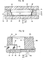
- Figs. 7 and 8 relate to another form of implementation of the method, in which the component formed by two parts, one of which is non-metallic and the other metallic, is a watch face.
- the component formed by two parts one of which is non-metallic and the other metallic, is a watch face.
- a matrix, designated by 29, is constituted by a first disc-shaped piece 30 of plastic material, which has in its lower face a flat bottom housing 31, a central core 32, provided with a head 32a and which is engaged in a central hole 33 of the plastic part 30 and of a stone glass plate 34, which is intended to constitute one of the. components of the manufactured component.
- This thin plate has been machined beforehand, with a central hole and two parallel main faces which are polished so as to present their final surface condition.
- this plate 34 is glued in a recess formed in the bottom of the housing 31, so that it is integral with the matrix 29.
- a coating 35 is formed on all surfaces of the housing 31 formed of a metal which is a good conductor of electricity. It goes without saying, however, that, depending on the case, in particular if the plate 34 is transparent, it will be advisable to form beforehand, on the lower surface of the plate head and on its edge; a metallic coating which gives the dial an aesthetic appearance as good as possible. On the other hand, the coating 35 must be sufficiently adherent and thick to ensure the connection between the plate 34 and the support body which is formed during the following operation.
- the electro-forming operation is then carried out by placing the matrix shown in fig. 7 in a galvanic bath capable of causing the deposit on the conductive coating 35 of a metal such as nickel or, if necessary, a noble metal such as gold, platinum or silver or even the formation of an alloy having the properties and characteristics that one wishes to have.
- the metal body 36 which is formed during the galvanic operation has a lower surface irregular but adheres perfectly to metallized surfaces 35. The thickness of this deposit gradually increases and the operation is continued until the desired mass has been obtained.
- the following operation consists in machining the body 36 according to the surfaces designated by the dashed lines 37 and 38, then in eliminating the rest of the matrix, for example by dissolution.
- a composite dial plate is thus obtained, the central part of which is constituted by the plate 34 which can be extremely thin and the metal support which extends under this plate 34 and around its periphery consists of what remains of the body 38 and ensures the mechanical holding of the plate 34. It has in fact been found that the electro-forming operation makes it possible to produce composite bodies the different parts of which are linked to each other without internal tension, so that the fragility of the glass or of the stone used for the part 34 is entirely attenuated by the presence of the body 38 which forms its support and its lining.
- the described application of the method according to the present invention makes it possible to produce composite dials in which the plate glass or semi-precious stone 34 will have a thickness of the order of 20/100 mm while the body 38 will have a thickness of the order of 15/100 mm or even less.
- the total thickness of the dial plate is therefore less than 4/10 mm of conventional dials.
- Fig. 8 shows the final termination of the dial.
- This figure shows the plate 34 which is entirely disengaged from the matrix 29 and the packing body 38 which adheres to the plate. 34 per tou te the bottom surface of this plate.
- the metal part 38 of the dial plate could undergo, after the elimination of the matrix, a metallization operation intended to provide it with a coating of a noble metal and thus to improve its appearance.
- a foot 39 is shown in FIG. 8. As can be seen, it is welded to the lower surface of the body 38.
- the elements for fixing the dial can be produced in the form feet fixed by welding, that is to say in fact by brazing according to an operation quite usual in this field of technology.
- the thickness of the body 38 is sufficient at the location of the foot 39 so that the brazing operation can be carried out without the metal coating 35 changing characteristics.
- the plate 34 is a transparent plate, without this coating changing color.
- tests have shown that with a thickness of 15/100 mm, this result was already obtained. However, it can still be considered that it is possible to obtain this result with a thickness of the body 38 still less than 15/100 mm.
- Fig. 9 illustrates an application of the method to the manufacture of a watch dial in which the hour signs of the hour turn can have a particularly remarkable appearance.
- the time signs consist, for example, of metallic indexes in gold and formed on the back of the plate 34, the latter being of a material transparent.
- Gold indexes are then covered with a second metallized layer forming the adhesion coating 35 of the body 38 and this second layer is for example in silver or in another white or gray metal, so as to bring out the metallized indexes in gold, on the other hand, in the embodiment illustrated in FIG. 9, another technique is applied to reveal the time signs.
- This figure in fact recognizes a dial plate made of transparent non-metallic material, designated by 40, a plastic matrix 41 in the housing of which the plate 40 is glued by its upper surface 42.
- the lower surface 43 of the plate dial 40 and the peripheral parts 44 and 45 of the housing in the matrix 41 are coated, by vacuum evaporation or ion spraying, or any other process allowing the deposition of particles in the gas phase, with a layer of metallic coating which is however interrupted at locations 46 where there must be hour markers.
- These indexes are formed themselves by depositing a dye, designated by 47, and covering this dye by metal trim pieces 48 having for example the same structure as Paris nails. These elements are placed on the surface 43 of the glass 40 in order to surround and limit the shapes which the colored areas 47 draw.
- the assembly thus prepared is subjected to the electro-forming operation, as in the previous examples, and a metal body 49 is deposited in the housing of the matrix.
- the elements 48 are themselves metallic, it is clear that they themselves receive, on their external surface, the deposit of metal formed by electro-forming. They are therefore completely embedded in the body 49 as it grows.
- the edge of the plate 40 is beveled here in order to reduce the irregularities tees of the deposition of the body 49.
- the electro-forming operation is interrupted, then the body 49 is machined in the same manner as in the previous embodiment, so that the surfaces 50 and 51 are turned and limit the dimensions of the dial plate.
- the rest of the matrix 41 can then be eliminated, for example, by dissolution or any other suitable means and it only remains to weld the feet of the dial as we have seen in relation to fig. 8.
- a metal part such as the parts 48 which are either decorative parts or, where appropriate, parts exercising a function of fixing or rigidity of the component described, these parts being made integral with the component by the metallic mass which increases during the electro-forming operation.
- these auxiliary parts could also be fixed to the non-metallic part by engagement in openings or recesses in this part.
- the essential advantage of the process described is that, from a thin metallic coating formed in the gaseous phase on the previously prepared surface of a non-metallic part, a metallic mass can be grown whose thickness reaches macroscopic values without internal tension.
- This growth-formed body has sufficient rigidity and adhesion to the non-metallic part so that it can serve as a support element, if necessary, after having been machined to the desired shape.
- the thickness of this body formed by growth can reach values such that it constitutes a mounting element acting by its legitimateness and its shape. The thickness can also become such that it is possible to carry out a welding operation on this body, so that a complete component is thus obtained having complete material continuity between the non-metallic part and the metallic part and in which the adhesion between the different parts is perfectly achieved.
- the auxiliary elements which are embedded in the body formed by growth will also serve to reinforce the homogeneity of the component.
- the method of the invention can also be applied to the formation of other clothing components, for example to composite plates capable of being fixed on the bracelet elements. We can also foresee the formation of decor on other parts of the box like the middle or the bottom.
- materials for the part made of non-metallic material it is possible to provide not only mineral glass, sapphire or different stones, as mentioned in the description of the different embodiments, but also, for example, plates made of ceramic materials or elements made of metal oxides or other non-metallic chemical compounds.
- a matrix intended to allow the manufacture of a middle part by growth in a galvanic bath consists of three separate main parts.
- the central part 61 is a plastic disc which can be circular or shaped, depending on the internal contour of the middle part. This disc is provided with a projecting collar 62 with a rectangular profile, which is intended to give its shape to the notch of ice of the middle part, as will be seen below.
- the cylindrical surfaces 63 and 64 of the part 61 will be metallized in order to subsequently allow the growth of the middle part.
- the front face 65 of the disc 61 will also be metallized and care will be taken that the metal covering which covers the surface 65 is in electrical contact with the cylindrical covering 64 which covers the lower part of the edge of the disc 61.
- the disc 61 is pinched between two non-metallized plastic discs 66 and 67, the diameters of which are greater than the outside diameter that the middle to be produced must include. These two discs are intended to be fixed each on one of the front faces of the disc 61. This fixing will be carried out preferably by gluing so that there is a seal as perfect as possible between the parts, in particular at the periphery of these this.
- the disc 67 which covers the metallized face 65 of the disc 61 will be pierced in its center with a hole making it possible to connect, for example by welding, a connection wire69 to the metal coating 65.
- the matrix can be immersed in a galvanic bath, the connection 69 being connected to one of the poles 70 of a current source while the electrolyte of the bath will be connected by electrodes at the other pole of the current source.
- this operation is interrupted and the matrix is eliminated, for example by dissolving in a bath containing a solvent for the plastic material constituting the matrix.
- the matrix being thus entirely eliminated, only the part 75 remains, the internal faces of which have a surface appearance which is determined faithfully by the shape of the initial metallic coatings 63 and 64 formed on the disc 61.
- the annular part 75 can also undergo termination operations, such as for example turning to a determined profile, along the dashed lines 76 which show not only the shape of the outer surface of the middle part thus obtained, but also the detachment at train for the introduction of connecting means to a bracelet.
- the recess formed by the collar 62 of the initial disc 61 which can serve as a notch of ice, makes it possible to engage in the middle a glass of organic or inorganic material, possibly held in place by a sealing ring.
- the growth face i.e. the surface of the matrix which is metallized, which is connected to a pole of the current source and which is in contact with the bath, namely the internal face of the disc 66 instead of being the lateral face of the disc 61.
- the lateral faces 63 and 64 being kept non-metallized, it would be the surface of the shoulder 11 which would also be metallized, the growth then leaving from the disc 66 between the wall of the disc 61 and from another external auxiliary part, not shown on the drawing, which gives the external shape of the part obtained.
- the method described also makes it possible to produce components of the clothing of a timepiece in which one or more non-metallic or metallic pieces are permanently linked to one or more metallic pieces, the latter being formed by growth.
- Figs. 11: and 12 show two variants of application of such methods.
- a sapphire crystal 77 is pre-machined according to the usual manufacturing methods for these parts, then it is provided on its reverse with a metallic coating 78 which covers the periphery of its lower face, that is to say of the one that will be used to mount it in the box.
- a metallic coating 78 which covers the periphery of its lower face, that is to say of the one that will be used to mount it in the box.
- Glass 77 thus prepared is incorporated into a composite matrix.
- the elements of the matrix are in very precise positions relative to the glass 77 .
- These elements first of all comprise a central disc 79 of plastic material, which will be fixed, for example by gluing, to the center of the upper face 80 of the glass and whose lateral surface outside 81 will extend so as to partially cover the covering 78.
- a second component 82. of the matrix is a plastic disc which has a central opening, the internal lateral face 8 3 of which is opposite the edge 81 of the part 79.
- the matrix is supplemented by a basic part 86 of plastic material. , having a central boss which is capped by a pressed metal cap 8 7.
- the internal periphery of the matrix part 82 that is to say the annular surface which is opposite the cap 87 and which is designated by 88 , will also be metallized, as well as the side of the housing which is limited by the lateral rim 89 of the part 32.
- metallized surface 78 is also connected to the metal cap 87, so that a pressure spring 90, housed in a central hole in the part 86, can be brought into contact with one of the poles of the current source and establishes an electrical connection out of contact with the metal of the bath, between the coating 78 and the current source.
- a pressure spring 90 housed in a central hole in the part 86, can be brought into contact with one of the poles of the current source and establishes an electrical connection out of contact with the metal of the bath, between the coating 78 and the current source.
- the adhesion of the metallic annular part formed on the back of the glass, with the latter, is determined by the adhesion of the metallic coating 78 and the coating formation techniques, for example by ionic deposition or by vacuum metallization, or projection of particles, allow for perfectly adherent deposits.
- the parts of the matrix which are made of plastic will be dissolved in a suitable solvent leaving the glass 77 intact.
- the metal parts 90 and 87 will be eliminated and finally the massive metal part, formed in the imprint 85, and constituting on the back of the glass a fixing flange, may be finished either by turning or by milling or other operations.
- the metal part linked to the sapphire, in this case a flange which allows the fixing in the box can also be the middle of the box itself.
- fig. 12 further illustrates one form of implementation of the method in which a sapphire crystal 91, consisting of a transparent planar plate is incorporated into a component of the watch case which comprises a massive metal middle directly connected to this glass.
- a coating 92 is formed by metallization on the outer periphery of the flat face 93 of the glass 91 intended to be turned towards the inside of the watch case.
- the central part of the internal surface 93 of the glass, as well as the edge 94 of this part are left free of coating.
- the glass 91 thus prepared is incorporated into a matrix which comprises, first of all, a central part 95 consisting of a plastic disc, fixed by gluing to the center of the surface 93 and whose dimensions are such that it partially covers the covering 92.
- This disc 95 is limited by a lateral face 96 which extends perpendicularly to the surface 93 and, consequently, to the covering 92. Care will be taken that the part 95 is fixed to the surface 93 so not to leave any play or any crack between the surface 96 and the coating 92.
- the glass 91 is glued to a support piece 97, also made of plastic, the upper surface of which is planar and shaped so as to receive the external planar surface 98 of the glass 91, that is to say a surface which is also flat and parallel to the surface 93.
- a metallic coating 99 of annular shape On this upper surface of the part 97 is deposited a metallic coating 99 of annular shape, dimensioned to extend outside the limit surface 94 of the glass 91.
- a peripheral part 100 also made of plastic, of annular shape, having an internal surface 101 whose generatrices are perpendicular to the planar surface 99.
- This external part 100 will be glued to the support 97 so that the surface 101 delimits, with the surface of the part 95 and the faces 92 and 94 of the glass 91, an imprint of rectangular profile having a recess, as seen in FIG. 12, this imprint representing the shape of the middle part which it is desired to obtain.
- the metal covering 99 extends laterally, at least in the form of a tongue, outside the limit surface 101 so as to be able to be connected by a line 102 to a pole 103 of the current source , this line passing through a hole 104 in part 97.
- the metal dissolved in the bath begins by depositing on the coating 99 and grows in the form of a homogeneous mass which is guided by the guide faces 94 and 101 until that the filling reaches the level of the surface 92 .
- the metallized surface 92 is also connected to the current source via the filling formed in the bottom of the imprint and the growth continues, the faces 96 and 101 then constituting the insulating guide faces which determine the shape of the homogeneous mass intended to constitute the desired build.
- the upper part of the matrix is removed by turning so that the square obtained has a flat and regular underside 105
- these decorations could be formed by a particular structure of the metallization layer 99 comprising for example zones made of metals having structures in particular of different colors. These decorations could be obtained using the mask technique.
- the decoration of the upper surface of the middle part could be obtained in the form of relief, the mold used to form the part 97 comprising the required decoration. It is known in fact that, provided that the relief of such a decoration is not too pronounced, it does not disturb the deposit of metal during the growth operation, so that the lower surface of the middle part presents, so quite faithful, the allure of the decoration which the matrix included.
- the method described in relation to FIG. 12 applies not only to the production of components of watch cases formed from glass permanently bonded to the middle or to a bezel, but also to the fabricadtion of glasses or composite middle of annular shape, comprising for example an external element in a metallic or non-metallic material difficult to machine and inside this external element a solid internal coating in an easily machinable metal.
- This will present, either by electro-forming or by subsequent machining operations, surfaces adjusted to receive the movement or to secure the bottom.
- the method described also makes it possible to fill, with an easily machinable metal, housings of coarse dimensions formed inside a horn made of metallic or non-metallic material which is difficult to machine.
- connection between the different parts of the matrix can be done other than by gluing, for example by ultrasonic welding of the assembly of auxiliary parts with the base part. All that is required is a bonding operation which takes place at the periphery of the matrix.
- the imprint could be covered by certain non-metallic parts without this interfering with growth.
- the auxiliary parts of the impression for example the parts 84 and 82, can be injected in a single part comprising radial arms connecting them above the slot which separates them. This considerably simplifies the manufacture of the dies, and plays an important role in the profitability of the process, since all the dies must be destroyed by dissolution in order to release the part obtained by the process.
- the constitution of the baths and the conduct of the growth operation must be provided according to the rules known in this technique.
- the parameters must be adapted as a function of growth in a thick layer. It is indeed advisable to choose the metals and the operating conditions so as to obtain masses as free as possible from internal tensions. Nickel, gold, copper, meet these conditions particularly well.
Landscapes
- Physics & Mathematics (AREA)
- General Physics & Mathematics (AREA)
- Engineering & Computer Science (AREA)
- Optics & Photonics (AREA)
- Plasma & Fusion (AREA)
- Manufacturing & Machinery (AREA)
- Chemical & Material Sciences (AREA)
- Crystallography & Structural Chemistry (AREA)
- Adornments (AREA)
Applications Claiming Priority (4)
| Application Number | Priority Date | Filing Date | Title |
|---|---|---|---|
| CH5949/82 | 1982-10-11 | ||
| CH594982A CH649670GA3 (en) | 1982-10-11 | 1982-10-11 | Process for the manufacture of a component of the cladding of a timepiece and component obtained by this process |
| CH2284/83 | 1983-04-28 | ||
| CH228483A CH649891GA3 (en) | 1983-04-28 | 1983-04-28 | Method of manufacturing a component for housing a timekeeper and component obtained according to this method |
Publications (1)
| Publication Number | Publication Date |
|---|---|
| EP0106806A1 true EP0106806A1 (de) | 1984-04-25 |
Family
ID=25690012
Family Applications (1)
| Application Number | Title | Priority Date | Filing Date |
|---|---|---|---|
| EP19830810467 Withdrawn EP0106806A1 (de) | 1982-10-11 | 1983-10-10 | Verfahren zur Herstellung eines äusseren Uhrenteiles und durch dieses Verfahren hergestelltes Teil |
Country Status (1)
| Country | Link |
|---|---|
| EP (1) | EP0106806A1 (de) |
Cited By (3)
| Publication number | Priority date | Publication date | Assignee | Title |
|---|---|---|---|---|
| EP0716360A1 (de) | 1995-08-30 | 1996-06-12 | Fabrique D'ebauches De Sonceboz S.A | Uhrengehäuse mit ausgehöhltem Gehäuseteil und Gehäuseanpassungsmittel sowie eine mit einem solchen Gehäuse ausgerüstete Uhr |
| EP2380864A1 (de) * | 2010-04-23 | 2011-10-26 | Omega SA | Keramikelement mit mindestens einem Metalldekoreinsatz |
| CN106462111A (zh) * | 2014-06-03 | 2017-02-22 | 斯沃奇集团研究和开发有限公司 | 由焊接材料制成的用于钟表的由外部零件组成的构件 |
Citations (3)
| Publication number | Priority date | Publication date | Assignee | Title |
|---|---|---|---|---|
| CH332904A (fr) * | 1955-09-27 | 1958-09-30 | Flueckiger & Cie | Procédé de fabrication de cadrans à signes en creux ou en relief |
| US3228861A (en) * | 1960-11-30 | 1966-01-11 | Vogt | Electroplating method for producing watch dial indicia |
| DE1621034A1 (de) * | 1967-02-08 | 1971-04-08 | Balco Filtertechnik Gmbh | Verfahren zur Herstellung einer Matrize fuer die galvanoplastische Herstellung von Metallfolien |
-
1983
- 1983-10-10 EP EP19830810467 patent/EP0106806A1/de not_active Withdrawn
Patent Citations (3)
| Publication number | Priority date | Publication date | Assignee | Title |
|---|---|---|---|---|
| CH332904A (fr) * | 1955-09-27 | 1958-09-30 | Flueckiger & Cie | Procédé de fabrication de cadrans à signes en creux ou en relief |
| US3228861A (en) * | 1960-11-30 | 1966-01-11 | Vogt | Electroplating method for producing watch dial indicia |
| DE1621034A1 (de) * | 1967-02-08 | 1971-04-08 | Balco Filtertechnik Gmbh | Verfahren zur Herstellung einer Matrize fuer die galvanoplastische Herstellung von Metallfolien |
Non-Patent Citations (1)
| Title |
|---|
| DIE UHR, vol. 19, no. 17, 5 septembre 1965, pages 131-136 * |
Cited By (8)
| Publication number | Priority date | Publication date | Assignee | Title |
|---|---|---|---|---|
| EP0716360A1 (de) | 1995-08-30 | 1996-06-12 | Fabrique D'ebauches De Sonceboz S.A | Uhrengehäuse mit ausgehöhltem Gehäuseteil und Gehäuseanpassungsmittel sowie eine mit einem solchen Gehäuse ausgerüstete Uhr |
| EP2380864A1 (de) * | 2010-04-23 | 2011-10-26 | Omega SA | Keramikelement mit mindestens einem Metalldekoreinsatz |
| EP2383244A1 (de) * | 2010-04-23 | 2011-11-02 | Omega SA | Keramikelement mit mindestens einem Metalldekoreinsatz |
| CN102233702A (zh) * | 2010-04-23 | 2011-11-09 | 奥米加股份有限公司 | 镶嵌有至少一个金属装饰物的陶瓷元件 |
| CN105272379A (zh) * | 2010-04-23 | 2016-01-27 | 奥米加股份有限公司 | 镶嵌有至少一个金属装饰物的陶瓷元件 |
| US9453287B2 (en) | 2010-04-23 | 2016-09-27 | Omega Sa | Ceramic element inlaid with at least one metallic decoration |
| CN106462111A (zh) * | 2014-06-03 | 2017-02-22 | 斯沃奇集团研究和开发有限公司 | 由焊接材料制成的用于钟表的由外部零件组成的构件 |
| CN106462111B (zh) * | 2014-06-03 | 2019-08-09 | 斯沃奇集团研究和开发有限公司 | 由焊接材料制成的用于钟表的由外部零件组成的构件 |
Similar Documents
| Publication | Publication Date | Title |
|---|---|---|
| EP2315673B1 (de) | Durch einlegearbeiten hergestelltes dekorationselement | |
| KR20130038895A (ko) | 적어도 하나의 금속 장식으로 인레이된 세라믹 부재 | |
| EP2628607A1 (de) | Verankerungsvorrichtung einer Metall-Einlegearbeit | |
| EP0930835B1 (de) | Verfharen zum fassen von steinen an durch elektroformung hergestellten schmuck und so erhaltener schmuck | |
| CN103771907A (zh) | 覆盖有金属材料的选择性导电的陶瓷 | |
| EP3564758B1 (de) | Herstellungsverfahren von uhrenkomponenten, das eine schmuckbeschichtung mit aventurinquarz umfasst | |
| EP0041481B1 (de) | Uhrgehäuse | |
| EP3708384A1 (de) | Verkleidungselement oder zifferblatt einer uhr oder eines schmuckstücks aus leitendem material | |
| EP0106806A1 (de) | Verfahren zur Herstellung eines äusseren Uhrenteiles und durch dieses Verfahren hergestelltes Teil | |
| EP3202708A1 (de) | Verfahren zur herstellung einer hybrid-uhrenkomponente | |
| EP3246767B1 (de) | Herstellungsverfahren einer uhr, die mit einem hohlen oder reliefartigen verkleidungselement ausgestattet ist | |
| KR20210027052A (ko) | 기계 부품을 장식하기 위한 방법 | |
| EP1672436A1 (de) | Uhrzifferblatt und Herstellungsverfahren dieses Zifferblattes | |
| CH715336A2 (fr) | Procédé d'assemblage d'au moins deux éléments et composant d'habillage ainsi formé. | |
| EP3622846A1 (de) | Verfahren zum zusammenbau von mindestens zwei elementen | |
| EP3479721B1 (de) | Verfahren zum fassen eines steins | |
| EP3246766B1 (de) | Herstellungsverfahren einer uhr, die mit einem relief-verkleidungselement ausgestattet ist | |
| CH531737A (fr) | Procédé de fabrication d'un cadran d'horlogerie muni d'au moins un cadran de compteur ou de petite seconde et cadran d'horlogerie obtenu par ce procédé | |
| EP3814553B1 (de) | Herstellungsverfahren von dekorteilen | |
| EP3923088A1 (de) | Verfahren zur herstellung eines verzierungsteils aus hartem material, das mit einer polymerbeschichtung versehen ist | |
| EP3839659B1 (de) | Verfahren zur dekoration eines mechanischen bauteils | |
| WO2019158499A1 (fr) | Composant horloger intégrant au moins un élément d'ornement | |
| CH716645B1 (fr) | Procédé de fabrication d'un composant d'habillement pour pièce d'horlogerie ou de joaillerie et composant d'habillement en matériau d'origine naturelle revêtu. | |
| CH715925A2 (fr) | Élément d'habillage ou cadran d'horlogerie ou de bijouterie en matériau conducteur. | |
| CH715954B1 (fr) | Procédé de décoration d'une pièce mécanique. |
Legal Events
| Date | Code | Title | Description |
|---|---|---|---|
| PUAI | Public reference made under article 153(3) epc to a published international application that has entered the european phase |
Free format text: ORIGINAL CODE: 0009012 |
|
| AK | Designated contracting states |
Designated state(s): CH DE FR GB IT LI |
|
| 17P | Request for examination filed |
Effective date: 19840608 |
|
| STAA | Information on the status of an ep patent application or granted ep patent |
Free format text: STATUS: THE APPLICATION IS DEEMED TO BE WITHDRAWN |
|
| 18D | Application deemed to be withdrawn |
Effective date: 19871201 |