EP0103792A2 - Vorrichtung zum temperatur- und/oder stromabhängigen Schalten einer elektrischen Verbindung - Google Patents
Vorrichtung zum temperatur- und/oder stromabhängigen Schalten einer elektrischen Verbindung Download PDFInfo
- Publication number
- EP0103792A2 EP0103792A2 EP83108625A EP83108625A EP0103792A2 EP 0103792 A2 EP0103792 A2 EP 0103792A2 EP 83108625 A EP83108625 A EP 83108625A EP 83108625 A EP83108625 A EP 83108625A EP 0103792 A2 EP0103792 A2 EP 0103792A2
- Authority
- EP
- European Patent Office
- Prior art keywords
- contact
- counter
- bimetallic
- tongue
- temperature
- Prior art date
- Legal status (The legal status is an assumption and is not a legal conclusion. Google has not performed a legal analysis and makes no representation as to the accuracy of the status listed.)
- Granted
Links
- 230000013011 mating Effects 0.000 claims description 39
- 210000002105 tongue Anatomy 0.000 claims description 38
- 238000013459 approach Methods 0.000 claims description 5
- 230000001419 dependent effect Effects 0.000 claims description 4
- 238000000576 coating method Methods 0.000 abstract description 4
- 230000000694 effects Effects 0.000 abstract description 4
- 238000013461 design Methods 0.000 abstract description 3
- 230000001681 protective effect Effects 0.000 abstract 1
- 238000001816 cooling Methods 0.000 description 6
- 238000004519 manufacturing process Methods 0.000 description 6
- 238000011109 contamination Methods 0.000 description 3
- 238000000034 method Methods 0.000 description 3
- 230000008569 process Effects 0.000 description 3
- 238000000926 separation method Methods 0.000 description 3
- 238000005452 bending Methods 0.000 description 2
- 230000008859 change Effects 0.000 description 2
- 238000011161 development Methods 0.000 description 2
- 230000018109 developmental process Effects 0.000 description 2
- 238000005516 engineering process Methods 0.000 description 2
- 229910052751 metal Inorganic materials 0.000 description 2
- 239000002184 metal Substances 0.000 description 2
- 230000003647 oxidation Effects 0.000 description 2
- 238000007254 oxidation reaction Methods 0.000 description 2
- 238000007789 sealing Methods 0.000 description 2
- 230000007704 transition Effects 0.000 description 2
- 239000000356 contaminant Substances 0.000 description 1
- 230000007797 corrosion Effects 0.000 description 1
- 238000005260 corrosion Methods 0.000 description 1
- 238000010438 heat treatment Methods 0.000 description 1
- 238000009434 installation Methods 0.000 description 1
- 239000011810 insulating material Substances 0.000 description 1
- 230000002427 irreversible effect Effects 0.000 description 1
- 230000007257 malfunction Effects 0.000 description 1
- 238000012986 modification Methods 0.000 description 1
- 230000004048 modification Effects 0.000 description 1
- 238000012544 monitoring process Methods 0.000 description 1
- TWNQGVIAIRXVLR-UHFFFAOYSA-N oxo(oxoalumanyloxy)alumane Chemical compound O=[Al]O[Al]=O TWNQGVIAIRXVLR-UHFFFAOYSA-N 0.000 description 1
- 239000003507 refrigerant Substances 0.000 description 1
- 238000005057 refrigeration Methods 0.000 description 1
- 230000000284 resting effect Effects 0.000 description 1
Images

Classifications
-
- H—ELECTRICITY
- H01—ELECTRIC ELEMENTS
- H01H—ELECTRIC SWITCHES; RELAYS; SELECTORS; EMERGENCY PROTECTIVE DEVICES
- H01H37/00—Thermally-actuated switches
- H01H37/02—Details
- H01H37/32—Thermally-sensitive members
- H01H37/52—Thermally-sensitive members actuated due to deflection of bimetallic element
- H01H37/54—Thermally-sensitive members actuated due to deflection of bimetallic element wherein the bimetallic element is inherently snap acting
- H01H37/5427—Thermally-sensitive members actuated due to deflection of bimetallic element wherein the bimetallic element is inherently snap acting encapsulated in sealed miniaturised housing
-
- H—ELECTRICITY
- H01—ELECTRIC ELEMENTS
- H01H—ELECTRIC SWITCHES; RELAYS; SELECTORS; EMERGENCY PROTECTIVE DEVICES
- H01H1/00—Contacts
- H01H1/12—Contacts characterised by the manner in which co-operating contacts engage
- H01H1/14—Contacts characterised by the manner in which co-operating contacts engage by abutting
- H01H1/18—Contacts characterised by the manner in which co-operating contacts engage by abutting with subsequent sliding
-
- H—ELECTRICITY
- H01—ELECTRIC ELEMENTS
- H01H—ELECTRIC SWITCHES; RELAYS; SELECTORS; EMERGENCY PROTECTIVE DEVICES
- H01H37/00—Thermally-actuated switches
- H01H37/02—Details
- H01H37/32—Thermally-sensitive members
- H01H37/52—Thermally-sensitive members actuated due to deflection of bimetallic element
- H01H37/54—Thermally-sensitive members actuated due to deflection of bimetallic element wherein the bimetallic element is inherently snap acting
- H01H2037/5463—Thermally-sensitive members actuated due to deflection of bimetallic element wherein the bimetallic element is inherently snap acting the bimetallic snap element forming part of switched circuit
-
- H—ELECTRICITY
- H01—ELECTRIC ELEMENTS
- H01H—ELECTRIC SWITCHES; RELAYS; SELECTORS; EMERGENCY PROTECTIVE DEVICES
- H01H37/00—Thermally-actuated switches
- H01H37/002—Thermally-actuated switches combined with protective means
-
- H—ELECTRICITY
- H01—ELECTRIC ELEMENTS
- H01H—ELECTRIC SWITCHES; RELAYS; SELECTORS; EMERGENCY PROTECTIVE DEVICES
- H01H37/00—Thermally-actuated switches
- H01H37/02—Details
- H01H37/32—Thermally-sensitive members
- H01H37/52—Thermally-sensitive members actuated due to deflection of bimetallic element
- H01H37/54—Thermally-sensitive members actuated due to deflection of bimetallic element wherein the bimetallic element is inherently snap acting
- H01H37/5418—Thermally-sensitive members actuated due to deflection of bimetallic element wherein the bimetallic element is inherently snap acting using cantilevered bimetallic snap elements
Definitions
- the invention relates to a device for temperature and / or current-dependent switching of an electrical connection, such as a temperature controller monitor or the like.
- a device for temperature and / or current-dependent switching of an electrical connection such as a temperature controller monitor or the like.
- a device for temperature and / or current-dependent switching of an electrical connection such as a temperature controller monitor or the like.
- a movable contact switchable when a predetermined temperature limit is exceeded by means of a bimetal element and a counter contact contact and counter contact with connection elements for Connection of supply lines are provided.
- the bimetal element carrying the movable contact urges further and further against contact and can be subject to irreversible changes, in particular deformations, which change pure switching temperatures beyond specified tolerances.
- the invention is therefore based on the object of providing such a device which is easy to manufacture in terms of production technology and in which a change in switching temperature is reliably avoided.
- the above-mentioned object is achieved in a device of the generic type in that the contact and counter-contact are connected to connecting elements which are kept at a distance by a common, insulating support part, and in that the counter-clock is elastically resiliently mounted on the support part.
- the device can be designed either as a make contact or as a break contact;
- the connection between the contact and the mating contact can therefore be broken if the temperature is too high than a predetermined switching temperature, for example in the case of a motor or the like for interrupting operation or as a controller in a heating device, while it is below the switching temperature Temperature closes;
- a predetermined switching temperature for example in the case of a motor or the like for interrupting operation or as a controller in a heating device, while it is below the switching temperature Temperature closes;
- the connection is opened at a temperature below the switching temperature and that the connection is closed at a temperature above the switching temperature, for example in the case of a cooling device, etc.
- the bimetal element can in principle be electrically conductive myself and, if appropriate, also as current-sensitive switch act, so switch its switching process not based on any ambient temperature, but on the basis of the heat generated directly in it by the current flow itself; in this case, of course, it opens when the heat is excessively generated, since this is only generated in the closed state.
- configurations are also possible in which the bimetal element is current-free and the current is conducted via other elements for movable contact, as is known in principle in a wide variety of ways.
- the support part is annular and on the one hand carries a substantially circular bimetal element on its circumference, which be Moving contact switches and on the other hand an elastic disc spring, which carries the mating contact, defines its circumference.
- the mating contact is arranged at one end of an elongated elastic tongue, a mating contact also being mounted on the supporting part; that the mounting of the counter-contact tongue takes place in that it is fixed to the supporting part with the section, and that the bimetallic element is also designed to be elongated, carries the movable contact at one end and is fixed to the supporting part with a non-contact area.
- the mating contact tongue is formed in one piece with its connecting element, and that the bimetallic element is connected to a conductive part, which on the one hand is frictionally attached to the supporting part and on the other hand forms a connecting element for the movable contact and / or that on Support part approaches are formed with undercuts, and that the connecting piece connected to the bimetallic element has edges which are bent out of its plane, and in this way the undercuts are introduced between the approaches and a central section of the supporting part, the edges of the approaches and the actual connecting piece at the central section being clamped of the supporting part abuts, and that edges corresponding to the edges are also formed on the counter-contact tongue in the region of a section, that the section is inserted with its edges in the undercuts corresponding to undercuts.
- the switch has considerable manufacturing advantages.
- the contact unit formed from the contact, the bimetal element, the connecting piece connected to this and the connecting piece formed integrally with this connecting piece on the one hand, and the counter-contact unit formed from the mating contact and the counter-contact tongue and the connecting element formed integrally with the connecting element, are only used to manufacture the switch clamped pressed into the prefabricated supporting part, the connecting elements being pushed through areas kept free between the respective two approaches.
- the switch manufactured in this way can then be used directly at its work station.
- the connection elements can be bent in a corresponding manner before attachment to the support part or afterwards, the latter is useful, for example, if an end plate is formed on the support part, around the edge of which the connection elements are then preferably guided around.
- the assembly described can be done fully automatically. Instead of being used at its operating point of the switch, which is complete in this respect, it can also be inserted into a housing, in which case a front end of the support part, which may be designed as an end plate, forms the end, while the other housing is designed in the form of a pocket.
- the connection elements are led out between the front plate and the housing and sealed at their lead-through points.
- the bimetallic element and / or the counter-contact tongue to shorten the free oscillating length of the Part profiles are formed, in the area of which the parts themselves are rigid, that is, not elastic or movable. If, for example, the mating contact is attached to a long tongue which is mounted on the supporting part at a greater distance from the mating contact, the free-swinging length or the lever arm can be shortened by such profiling. In the area of the profiling, the tongue is practically there and not elastic, it only remains elastic in the unprofiled, shorter area and can swing back into this area.
- the invention proposes to have contact and counter-contact switched by different bimetallic elements, one in particular being able to have current flowing through it and therefore forming a current-sensitive switch, while the other is electrically unloaded and only responds to the ambient temperature.
- the bimetallic element which is not affected by the current and is only temperature-sensitive, can act as a thermostat or controller, for example, to regulate the current flow to a cooling device or a heater, while the current-carrying bimetal element fulfills a monitoring function in the event of excessive current flow, for example a short circuit, and in this case causes a separation . It can be adjusted very well at what load, ie what current flow over which period of time the switching process should start. When coordinating the different switching conditions of the two bimetal elements, the most varied combinations can be selected.
- the device according to the invention for temperature-dependent switching of an electrical connection has a support part 1 for the essential switching elements in the exemplary embodiment shown.
- the device can be surrounded by a housing 2, as is the case in the illustrated embodiments; but this need not be so, the device could also be used in a recess in the device to be controlled or monitored or the like, a protruding end plate 3 at one end of the support part 1 completely closing the opening of such a recess.
- a switch according to the invention could also be used in the recess there.
- the device according to the invention has a movable contact 6 on the one hand and a mating contact 7 assigned to it on the other hand.
- the contact 6 is formed at the front end of an elongated, tongue-shaped bimetal element 8, which is fastened with its rear end 9 to a connecting piece 11, for example welded to tongues formed thereon, which merges into a connecting element 12 projecting from the supporting part 1 via its end plate 3 .
- the contact unit formed by the parts 6, 8, 9, 11 could be fastened to the support part 1, which consists of insulating material, by screwing or riveting in the area of the connecting piece.
- the support part 1 points upwards and inwards from its central section 13 on its two edges projecting lugs 14, 14 ', which form groove-shaped undercuts 16, 16' towards the central part 13 ( Figure 3).
- edge regions 17, 17 'of the same are bent out of the plane of the actual connecting piece 11 somewhat more than this corresponds to the height of the undercuts 16, 16'.
- the unit 6, 8, 9, 11, 12 is with its connector.
- the mating contact 7 is formed at the front end of a mating contact tongue 18, which is formed in a transition section 19 in the manner corresponding to the connecting piece 11, described with reference to FIG. 3, and from which it integrally merges into an associated connecting element 21, and such forms a counter-contact unit 7, 18, 19, 21, which, as said, is also fixed to the support part 1 in the manner explained with reference to the contact unit 6, 8, 9, 11, 12.
- the mating contact tongue 18 consists of an inherently elastic metal part, such as an elastic sheet metal part. Since, as said, it is only fastened in the area of the transition piece 19, the counter-contact 7 can evade a pressure acting on it, in which the counter-contact tongue 18 bends elastically away from the supporting part 1.
- the mating contact tongue 18 can in a suitable manner be a profile 22, as is the case in the illustrated embodiment, this profiling 22 stiffening the mating contact tongue 18 over its length.
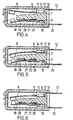
- FIG. 1 shows the preferred embodiment of the device in a contact interruption position, which generally corresponds to a high-temperature position, in which the temperature is therefore above a predetermined value and therefore a power interruption must take place.
- the bimetallic element 6 bends in the manner shown in FIG. 1 and lifts the contact 6 from the mating contact 7, so that the current is interrupted. If the temperature now drops below a predetermined value, the bimetallic disc 8 jumps over from its position shown in FIG. 1 and thus brings the contact 6 into contact with the mating contact 7.
- the bimetallic element 8 bends just so far that the Contact comes into contact with the counter contact 7, ot that the contact 6 exerts a greater force on the counter contact 7, so that the latter itself largely remains in its position shown in FIG. 1.
- the elastically bendable mating contact tongue can now be used due to the elastic mounting of the mating contact 7 18 recede and give way to the force of the Bielement 8 against. This avoids that at such low temperatures the internal stress of the bimetal element becomes extremely large on the one hand, but on the other hand it cannot bend further because its contact bears against a stationary mating contact, as a result of which the high voltages of the bimetal element at these low temperatures could lead to damage to the bimetal element itself, plastic changes and, in particular, considerable changes in the switching temperature.
- the tolerance limit of the switching temperature of the bimetal element 8 is always maintained under all conditions.
- the bimetal element 8 moves or pivots over its entire length from its end 9 attached to the connecting piece 11 to the contact 6.
- the force of the counter-contact tongue 18 can spring back only in its shorter area between the counter-contact 7 and the front end of the profiling 22.
- the free spring length of the bimetallic element 8 on the one hand and the counter-contact tongue 18 on the other hand is therefore different. This means that when the contact 6 comes into contact with the counter contact 7 and the counter contact 7 is pushed back by the contact 6, the contact 6 and the counter contact 7 do not always touch the same points, but rather they practically migrate and rub against each other.
- FIGS. 4 to 6 of the device according to the invention have two switching elements instead of one switching element, namely the bimetal element 8 of the embodiment of FIGS.
- a switching element can bring about temperature control by moving back and forth within certain temperature ranges, while the other switching element, such as the bimetallic element 8, merely monitors the temperature, i.e. ensures an interruption at excessively high temperatures.
- One switching element could also only respond to ambient temperatures, while the other switching element, such as the bimetallic element 8, responds to excessive current flow and causes an interruption of contact due to heat development in it caused by excessive current flow.
- FIGS. 4 to 6 is explained in detail below, the same reference numerals being used for the parts and elements already described with reference to FIGS. 1 to 3 and, insofar as is not absolutely necessary, no renewed explanation is carried out, but basically insofar reference is made to the explanation of the configuration of FIGS. 1 to 3.
- the supporting part 1 has on its side facing the counter-contact tongue 18 an annular recess 26 (which is also provided in the configuration of FIGS. 1 to 3, but has no special function there itself) ) with a central centering nose 27.
- a largely ring-shaped bimetal disc 28 is inserted into this recess between the central part 1 and counter-contact tongue 18, the bimetal disc 28 being centered by the centering lug 27 and held in place.
- the bimetallic disc 28 is inserted in such a way that it is at its low temperature position ( Figure 6) is unloaded and in particular the counter-contact tongue 18 can freely come to rest on the support part 1, while in its high temperature position ( Figures 5 and 6) with its inner circumference on the support part 1 and with its outer circumference on the counter-contact tongue 18 abuts and therefore pushes it away from the supporting part 1 1, so as to interrupt the electrical connection to the contact 6.
- the switching temperature of the bimetallic element 8 of the contact 6 is above the switching temperature of the bimetallic disc 28.
- FIG. 4 the position of the bimetallic element 8 and the bimetallic disc 28 is now shown at a temperature which is above both switching temperatures.
- the bimetallic element 8 lifts the contact 6 upwards and therefore initially causes an electrical separation.
- the bimetallic disc 28 pushes the mating contact tongue 18 and with it the mating contact 7 downward and likewise in turn causes an electrical separation of the contacts 6, 7.
- the ambient temperature drops to a value below the switching temperature of the bimetal element 8 but remains above the. Switching temperature of the bimetallic disc 28, the bimetallic element 8 snaps from the position in FIG. 4 to the position in FIG.
- the mating contact 7 can move freely downwards under the acting force of the contact 6, as has already been explained with reference to the configuration of FIGS. 1 to 3.
- the bimetallic element 8 does not have to switch under the effect of the ambient temperature, but can also shade itself due to the current flow and the temperature increase caused thereby.
- the bimetallic elements 8, 28 are arranged in such a way that they move the two contacts 6, 7 apart in their high-temperature positions, their switching temperatures must not be distributed in such a way that the switching temperature of the bimetallic element 8 is higher than that of the bimetallic disc 28. If the switching temperature the bimetallic disc 28 is higher than that of the bimetallic element 8 in the arrangement of the two elements shown, the bimetallic element 8 would still remain in its position corresponding to FIG. 4 at an ambient temperature between the two switching temperatures, while the bimetallic disc 28 and thus the mating contact Tongue 18 with its mating contact 7 would assume the position of FIG. 6, but the bimetallic element 8 would still interrupt the current flow.
- the two bimetallic elements 8, 28 do not have to be arranged in the manner shown that, in their high-temperature positions, they press the two contacts 6, 7 apart.
- the bimetallic disc 28 could be arranged in such a way that it corresponds to the figure 4 and 5 ent speaking position is the position below the switching temperature, i.e. the low temperature position and the position shown in FIG. 6 is the high temperature position, while the position of FIGS. 5 and 6 of the bimetal element 8 is the position for normal current flow and the position of FIG. 4 of the bimetal element 8 is the position with excessive current flow, for example a short circuit.
- the function would then be such that with normal current flow the bimetallic element 8 with the contact 6 is in the position of FIGS. 5 and 6 as the normal operating position. If the ambient temperatures are sufficiently low (it should be cooled) - the bimetallic disc is in the position of FIG. 5 and therefore cuts off the power supply to the cooling device. If the temperature now rises, the bimetallic disc 28 jumps to the position in FIG. 6 and therefore enables the circuit to be closed so that the optionally connected cooling device can work. Flows due to a malfunction or the like. an excessive current, the bimetallic element 8 can jump upward from the position of FIG. 6 due to the heat developing in it and detach the connection of the contact 6 to the mating contact 7, although cooling should actually be carried out from the ambient temperature.
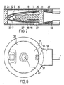
- FIGS. 7 and 8 show a further embodiment of the device according to the invention, which can be used particularly advantageously if the switching elements have to be arranged in a completely tight manner in a housing, as is important, for example, for use in refrigeration compressors, where hermetic sealing of the switching chamber is necessary , because the switch itself is flushed with refrigerant.
- the embodiment according to FIGS. 7 and 8 also initially generally has a supporting part 1.
- this supporting part is provided with an outer section designed as a ring 31.
- Metallic housing covers 32 and 33 are placed on both sides of the ring 31, which are firmly connected to the ring 31 and thus enclose a hermetically sealed chamber 34.
- the connection and sealing can take place in a wide variety of ways, for example the covers 32, 33 can be flanged at their edges and, if necessary, for this purpose.
- the ring 31 have corresponding outer grooves in which the flanged edges of the covers 32 and 33 engage.
- the ring 31 is metallized on its end faces, it could be designed, for example, as an insulating aluminum oxide body, and then the housing covers 32, 33 are soldered onto the ring, for example.
- the housing covers 32, 33 are punctiformly provided with notches 36, 37, on which the bimetallic element 8, which is largely also annular, and on the other hand the counter-contact tongue 18 are then fixed, for example soldered.
- the support member 1 carries the centering nose 27, which centers the centering of the further on the counter-contact tongue 18 and thus the counter-contact 7 acting bimetallic disc 28.
- Both housing covers 32, 33 are provided with connecting tongues 38, 39.
- the free length of the bimetal element 8 or the counter-contact tongue 18 also differed in this embodiment depending on the arrangement and design of the notches 36 and 37! I can be selected Except for the constructional differences shown and explained, the configuration according to FIGS. 7 and 8 functions and functions in the same way as the configurations explained above, in particular the configurations of FIGS. 4 to 6 provided with the second bimetallic disk 28, so that no need to go into this separately.
- the device according to the invention with its basic features enables further modifications and refinements.
- a current flow through the bimetallic element 8 itself could also be avoided and the bearing of the contact 6 could take place in a variety of other ways via movable cutting edge bearings or spring snap disks, which themselves conduct the current in the contacting device, while the bimetallic element itself does not correspond to the bimetallic disc 28 Current leads, but only causes the switching process.
- switching systems can also be used in the device according to the invention, as explained in various other applications and property rights of the inventor.
Landscapes
- Physics & Mathematics (AREA)
- Thermal Sciences (AREA)
- Thermally Actuated Switches (AREA)
- Emergency Protection Circuit Devices (AREA)
Abstract
Description
- Die Erfindung betrifft eine Vorrichtung zum temperatur- und/oder stromabhängigen Schalten einer elektrischen Verbindung, wie Temperaturregler -wächter od. dgl. mit mindestens einem bei Überschreiten einer vorbestimmten Temperaturgrenze mittels eines Bimetallelements schaltbaren beweglichen Kontakt und einem Gegenkontakt, wobei Kontakt und Gegenkontakt mit Anschlußelementen zum Anschluß von Zuleitungen versehen sind.
- Bei derartigen Vorrichtungen, beispielsweise solchen, die in ihrer Niedertemperaturstellung geschlossen sind, also bei denen in der Niedertemperaturstellung Kontakt und Gegenkontakt miteinander in Berührung stehen und die elektrische Verbindung herstellen, drängt das den beweg-I ichen Kontakt tragende Bimetal lel ement i mmer wei ter gegen den Kontakt und kann irreversible Veränderungen, insbesondere Verformungen unterliegen, die reine Schalttemperaturen über vorgegebene Toleranzen hinaus verändern.
- Der Erfindung liegt daher die Aufgabe zugrunde, eine derartige Vorrichtung zu schaffen, die fertigungstechnisch einfach herzustellen ist und bei der eine Schalttemperaturveränderung zuverlässig vermieden wird.
- Erfindungsgemäß wird die genannte Aufgabe bei einer Vorrichtung der gattungsgemäßen Art dadurch gelöst, daß Kontakt und Gegenkontakt mit durch ein ihnen gemeinsames, isolierendes Tragtei auf Abstand gehaltene Anschlußelemente verbunden sind und daß der Gegenhntakt elastisch nachgiebig am Tragteil gelagert ist. Die Vorrichtung kann dabei entweder als Schließer oder als Öffner ausgebildet sein; die Verbindung zwischen Kontakt und Gegenkontakt kann also gelöst werden, wenn die Temperatur zu hoch ist, alsa über einer vorgegebenen Schalttemperatur liegt, beispielsweise bei einem Motor od. dgl. zur Betriebsunterbrechung oder als Regler bei einer Heizeinrichtung, während sie bei einer unterhalb der Schalttemperatur liegenden Temperatur schließt; es kann aber auch vorgesehen sein, daß bei einer unterhalb der Schalttemperatur liegenden Temperatur eine Öffnung der Verbindung stattfindet und ein Schließen bei einer oberhalb der Schalttemperatur liegenden Temperatur erfolgt, beispielsweise bei einem Kühlgerät usw. Das Bimetallelement kann grundsätzl ich selbst stromleitend sein und gegebenenfalls auch als stromempfindlicher Schalter wirken, also sein Schaltvorgang nicht aufgrund irgendeiner Umgebungstemperatur, sondern aufgrund der in ihm durch den Stromfluß selbst direkt erzeugten Wärme schalten; hierbei öffnet es dann selbstverständlich bei übermäßig erzeugter Wärme, da diese ja nur im Schließzustand erzeugt wird. Grundsätzlich sind auch Ausgestaltungen möglich, bei denen das Bimetallelement stromfrei ist und die Stromleitung über andere Elemente zum beweglichen Kontakt erfolgt, wie dies in vielfältigster Weise grundsätzlich bekannt ist.
- Gemäß einer bevorzugten Ausführungsform ist vorgesehen, daß das Tragteil ringförmig ausgebildet ist und einerseits ein im wesentlichen kreisförmiges Bimetalleiement an seinem Umfang trägt, das den beweglichen Kontakt schaltet und andererseits eine elastische Tellerfeder, die den Gegenkontakt trägt, an ihrem Umfang festlegt. Gemäß einer anderen Ausgestaltung kann vorgesehen sein, daß der Gegenkontakt an einem Ende einer gestreckten el ast ischen Zunge angeordnet ist, wobei ein Gegenkontakt ferner Abschnitt am Tragteil gelagert ist; daß die Lagerung der Gegenkontakt-Zunge dadurch erfolgt, daß sie mit dem Abschnitt reibschlüssig am Tragteil festgelegt ist, und daß das Bimetallelement ebenfalls gestreckt ausgebildet ist, an einem Ende den beweglichen Kontakt trägt und mit einem kontaktfernen Bereich reibschlüssig am Tragteil festgelegt ist. Dabei sehen Weiterbildungen vor, daß die Gegenkontakt-Zunge einstückig mit ihrem Anschlußelement ausgebildet ist, und daß das Bimetallelement mit einem leitenden Teil verbunden ist, welches einerseits reibschlüssig am Tragteil festgelegt ist und andererseits einstückig ein Anschlußelement für den beweglichen Kontakt bildet und/oder daß am Tragteil Ansätze mit Hinterschneidungen ausgebildet sind, und daß das mit dem Bimetallelement verbundene Verbindungsstück aus seiner Ebene herausgebogene Ränder aufweist und derart die Hinterschneidungen zwischen den Ansätzen und einem Zentralabschnitt des Tragteils eingeführt ist, das unter Klemmwirkung die Ränder an den Ansätzen und das eigentliche Verbindungsstück am Zentralabschnitt des Tragteils anliegt, und daß an der Gegenkontakt- Zunge im Bereich eines Abschnitts ebenfalls den Rändern entsprechende Ränder ausgebildet sind, daß der Abschnitt mit seinen Rändern in den Hinterschneidungen entsprechenden Hinterschneidungen klemmend eingesetzt ist. In diesen Ausgestaltungen weist der Schalter erhebliche fertigungstechnische Vorteile auf. Die aus Kontakt, Bimetaltelement, mit diesem verbundenen Verbindungsstück sowie einstückig mit diesem ausgebildeten Anschlußstück gebildete Kontakteinheit einerseits und die aus Gegenkontakt und Gegenkontakt-Zunge sowie einstückig mit dieser ausgebildeten Anschlußelement gebildete Gegenkontakteinheit, werden zur Herstellung des Schalters ledigl ich klemmend in das vorgefertigte Tragteil eingedrückt, wobei die Anschlußelemente jeweils durch zwischen den jeweiligen beiden Ansätzen freigehaltene Bereiche hindurchgeschoben werden. Der so gefertigte Schalter kann dann unmittelbar an seiner Arbeitsstelle eingesetzt werden. Dabei können die Anschlußelemente vor Befestigung am Tragteil oder nachher in entsprechender Weise gebogen werden, letzteres ist beispielsweise sinnvoll, wenn am Tragteil eine Stirnplatte ausgebildet ist, um deren Rand die Anschlußelemente dann vorzugsweise herumgeführt sind. Der beschriebene Zusammenbau kann vollautomatisch erfolgen. Statt des Einsatzes an seiner Betriebsstelle des insoweit vollständigen Schalters kann er auch in ein Gehäuse eingesetzt werden, wobei dann ein vorderes, gegebenenfalls al s Stirnplatte ausgebildetes Ende des Tragteils den Abschluß bildet, während das sonstige Gehäuse taschenförmig ausgebildet ist. Die Anschlußelemente sind zwischen Stirnplatte und Gehäuse herausgeführt und an ihren Durchführungsstellen eingedichtet.
- Bei einer derartigen Vorrichtung, wie sie bisher beschrieben wurde, könnte sich das Problem ergeben, daß die elektrische Verbindung zwischen Kontakt und Gegenkontakt in der Berührungsstellung beispielsweise durch Korrodierung oder Verschmutzung vermindert wird, insbesondere wenn die Vorrichtung nicht in seinem separaten Gehäuse dicht eingesetzt ist, sondern sich in einer Umgebung, beispielsweise bei einem Motor od. dgl. befindet, in der Verschmutzungen richt auszuschließen sind oder aber die korrodierend ist. Es soll daher eine Vorrichtung der erläuterten Art derart weitergebildet werden, daß solche den Stromfluß reduzierende oder unterbrechende Beläge, wie Schmutz-oder Korrosionsschichten vermieden bzw., soweit sie anfallen, wieder entfernt werden. Erfindungsgemäß wird dieses Problem durch eine Ausgestaltung gelöst, bei der vorgesehen ist, daß die freien beweglichen Abschnitte des Bimetallelements und der Gegenkontakt-Zunge unterschiedliche Längen aufweisen. Durch die verschiedenen freien Armlängen der den Kontakt bzw. den Gegenkontakt tragenden Teile, also einerseits beispielsweise des den Kontakt tragenden Bimetallelements oder eines sonstigen diesen Kontakt tragenden Teils, andererseits einer den Gegenkontakt tragenden Zunge, bewegen sich Gegenkontakt und Kontakt auf Bögen mit unterschiedlichen Radien, was dazu führt, daß bei Berührung Kontakt und Gegenkontakt aufeinander reiben, wodurch Verschmutzungen oder Beläge durch die Reibwirkung entfernt werden und damit die elektrische Verbindung optimal, d.h. mit geringstem Übergangswiderstand hergestellt wird bzw. erhalten bleibt. Zur Bewirkung der unterschiedlichen freien beweglichen Armlänge des Kontakts bzw. des Gegenkontakts, insbesondere bei einer Lagerung derselben in einander gleichen Entfernungen am Tragteil, ist in bevorzugter Ausgestaltung vorgesehen, daß auf dem Bimetallelement und/oder der Gegenkontakt-Zunge zur Verkürzung der freien schwingenden Länge der Teile Profilierungen ausgebildet sind, in deren Bereich die Teile selbst steif, also nicht elastisch bzw. beweglich sind. Wenn also der Gegenkontakt beispielsweise an einer lange Zunge angebracht ist, die in einer größeren Entfernung vom Gegenkontakt am Tragteil gelagert ist, so kann die freischwingende Länge bzw. der Hebelarm durch eine solche Profilierung verkürzt werden. Im Bereich der Profilierung ist die Zunge praktisch da und nicht elastisch, sie bleibt nur in dem unprofilierten kürzeren Bereich elastisch und kann in diesen Bereich zurückschwingen.
- Bisher sind bei Vorrichtungen zum temperaturabhängigen Schalten elektrische Verbindungen, die in einer Einheit mit mehreren Funktionen, beispielsweise die eines Temperaturreglers und eines Schutzschalters erfüllen sollen, im Grund jeweils zwei verschiedene Vorrichtungen lediglich übereinander oder nebeneinander in einem Gehäuse angeordnet. Derartige bekannte Vorrichtungen sind fertigungstechnisch aufwendig herzustellen und verursachen praktisch den Aufwand zweier Schalter. Es stellt sich daher das Problem, eine gattungsgemäße Vorrichtung derart auszugestalten, daß sie ohne größeren Aufwand verschiedene Funktionen erfüllen kann. Gemäß einer erfindungsgemäßen Ausgestaltung wird demgemäß vorgeschlagen, daß ebenfalls der an sich unbewegliche, nur elastisch nachgiebig gelagerte Gegenkontakt durch ein weiteres Bimetallelement schaltbar ist. Bei dieser erfindungsgemäßen Ausgestaltung sind trotz der zwei verschiedenen Funktionen, die die Vorrichtung erfüllen kann, nur ein Kontakt und ein Gegenkontakt vorgesehen, im Gegensatz zu bekannten Vorrichtungen, bei denen jeweils zwei Kontakte und zwei Gegenkontakte vorgesehen sind, von denen zwei durch eine dauerhafte elektrische Verbindung miteinander verbunden sind, während die beiden anderen mit den nach außen führenden Anschlußelementen verbunden sind. Die Erfindung schlägt demgegenüber vor, Kontakt und Gegenkontakt von unterschiedlichen Bimetallelementen schalten zu lassen, wobei insbesondere eine stromdurchflossen sein kann und daher einen stromempfindlichen Schalter bildet, während das andere elektrisch unbelastet ist und nur auf die Umgebungstemperatur anspricht. Dabei kann das vom Strom unbelastete, lediglich temperaturempfindliche Bimetallelement beispielsweise als Thermostat bzw. Regler wirken, um den Stromfluß zu einem Kühlgerät oder einer Heizung regeln, während das stromdurchflossene Bimetallelement bei übermäßigem Stromdurchfluß, beispielsweise einem Kurzschluß eine Wächferfunktion erfüllt und in diesem Falle eine Trennung verursacht. Es kann dabei sehr gut genau eingestellt werden, bei welcher Belastung, d.h. welchem Stromfluß über welche Zeitdauer der Schaltvorgang einsetzen soll. Bei der Abstimmung der verschiedenen Schaltbedingungen der beiden Bimetaltelemente können dabei unterschiedlichste Kombinationen gewählt werden.
- Weitere Vorteile und Merkmale der Erfindung ergeben sich aus den Ansprüchen und aus der nachfolgenden Beschreibung, in der zwei Ausführungsbeispiele der erfindungsgemäßen Vorrichtung unter Bezugnahme auf die Zeichnung im einzelnen erläutert sind. Dabei zeigt:
- Figur 1 eine erste Ausführungsform der erfindungsgemäßen Vorrichtung in Öffnungsstellung; .
- Figur 2 die Ausführungsform der Figur 1 in Schließstellung;
- Figur 3 einen Schnitt durch die Ausführungsform der Figur 1 entlang der Linie III - III;
- Figur 4 eine weitere bevorzugte Ausführungsform der erfindungsgemäßen Vorrichtung mit zwei Schaltelementen in Öffnungsstellung beider Schaltelemente;
- Figur 5 die Ausführungsform der Figur 4 mit einem Schaltelement in Schließstellung, wobei aber weiterhin Kontaktunterbrechung durch die Öffnungsstellung des anderen Schaltelements gewährleistet ist;
- Figur 6 die Ausführungsform der Figur 4 mit beiden Schaltelementen in Schließstellung;
- Figur 7 eine weitere, im wesentlichen kreisförmige Ausführungstorm der erfindungsgemäßen Vorrichtung im Schnitt; und
- Figur 8 die Ausgestaltung der Figur 7 in Aufsicht in teilweise gebrochener Darstellung.
- Die erfindungsgemäße Vorrichtung zum temperaturabhängigen Schalten einer elektrischen Verbindung, also ein Temperaturregler, -wächter od. dgl. weist im dargestellten Ausführungsbeispiel ein Tragteil 1 für die wesentlichen Schaltelemente auf. Die Vorrichtung kann von einem Gehäuse 2 umgeben sein, wie es bei den dargestellten Ausführungsformen der Fal ist; dies muß aber nicht so sein, die Vorrichtung könnte auch geschützt in einer Ausnehmung des zu regelnden oder zu überwachenden Geräts od. dgl. eingesetzt werden, wobei eine überragende Stirnplatte 3 am einen Ende des Tragteils 1 die Öffnung einer solchen Ausnehmung vollständig verschließen würde. Ein solcher Einbau ist beispielsweise für einen ähnlich ausgestalteten Schalter in der DE-PS 29 16 639 (insbesondere Figuren 1 bis 3) beschrieben: In der dortigen Ausnehmung könnte auch ein erfindungsgemäßer Schalter eingesetzt werden.
- Die erfindungsgemäße Vorrichtung weist einerseits einen beweglichen Kontakt 6 und andererseits einen diesem zugeordneten Gegenkontakt 7 auf. Der Kontakt 6 ist am vorderen Ende eines gestreckten, zungenförmigen Bimetallelements 8 ausgebildet, welches mit seinem rückwärtigen Ende 9 an einem Verbindungsstück 11 befestigt, beispielsweise an an diesem ausgebildete Zungen angeschweißt ist, welches in ein vom Tragteil 1 über dessen Stirnplatte 3 hinausragendes Anschlußelement 12 übergeht. Die durch die Teile 6, 8, 9, 11 gebildete Kontakteinheit könnte am Tragteil 1, das aus isolierendem Material besteht, durch Verschraubung oder Festnietung im Bereich des Verbindungsstücks befestigt sein. Beim dargestellten Ausführungsbeispiel ist die Befestigur allerdings in der folgenden Weise vorgenommen: Das Tragteil 1 weist an seinen beiden Rändern von seinem Zentralabschnitt 13 nach oben und inn ragende Ansätze 14, 14' auf, die nutenförmige Hinterschneidungen 16, 16' zum Zentralteil 13 hin bilden (Figur 3). Am Verbindungsstück 11 sind Randbereiche 17, 17' desselben aus der Ebene des eigentl ichen Verbindungsstücks 11 etwas mehr herausgebogen, als dies der Höhe der Hinterschneidungen 16, 16' entspricht. Die Einheit 6, 8, 9, 11, 12 ist mit ihrem Verbindungsstück. 11 und dessen herausgebogenen Rändern 17, 17' derart in die am Tragteil 1 gebildeten Hinterschneidungen 16, 16' eingeschoben, daß es mittels des am Zentralabschnitt 13 des Tragteils 1 anl iegenden eigentlichen Verbindungsstück 1 und der an den nach innen ragenden Ansätzen 14, 14' anliegenden Ränder 17, 17' verspannt ist. Diese Ausgestaltung, mittels der in ähnlicher Weise der Gegenkontakt 7 am Tragteil 1 festgelegt ist, so daß dies nicht im einzelnen erneut beschrieben werden muß, ermöglicht einen fertigungstechnisch recht einfachen und materialmäßig recht sparsamen Zusammenbau der erfindungsgemäßen Vorrichtung.
- Der Gegenkontakt 7 ist am vorderen Ende einer Gegenkontakt-Zunge 18 ausgebildet, die in einem Übergangsabschnitt 19 in der dem Verbindungsstück 11 entsprechenden, unter Bezugnahme auf die Figur 3 beschriebenen Weise ausgebildet ist und von diesem aus einstückig in ein zugehöriges Anschlußelement 21 übergeht, und derart eine Gegenkontakteinheit 7, 18, 19, 21 bildet, die, wie gesagt, in der unter Bezugnahme auf die Kontakteinheit 6, 8, 9, 11, 12 erläuterten Weise ebenfalls am Tragteil 1 festgelegt ist.
- Die Gegenkontaktzunge 18 besteht aus einem an sich elastischen Metall - teil, wie einem elastischen Blechteil. Da sie, wie gesagt, lediglich im Bereich des Übergangsstückes 19 befestigt ist, kann der Gegenkontakt 7 einem auf ihn einwirkenden Druck ausweichen, in dem die Gegenkontakt-Zunge 18 sich elastisch vom Tragteil 1 fortbiegt. Zur Einstellung der zum Fortbiegen erforderlich Kraft einerseits, zum anderen zur Einstellung der tatsächlich biegbaren Länge der Gegenkontaktzunge 18 kann in geeigneter Weise auf dieser eine Profilierung 22 ausgeprägt sein, wie dies beim dargestellten Ausführungsbeispiel der Fall ist, wobei diese Profilierung 22 über ihre Länge hin die Gegenkontaktzunge 18 versteift.
- In der Figur 1 ist die bevorzugte Ausführungsform der Vorrichtung in einer Kontakt-Unterbrechungsstellung gezeigt, die im allgemeinen einer Hochtemperaturstellung entspricht, bei der also die Temperatur oberhalb eines vorgegebenen Wertes liegt und daher eine Stromunterbrechung erfolgen muß. Bei dieser hohen Temperatur biegt sich dasBimetatlelement 6 in der in Figur 1 dargestellten Weise und hebt den Kontakt 6 vom Gegenkontakt 7 ab, so daß es zur Stromunterbrechung kommt. Sinkt die Temperatur nun unter einen vorgegebenen Wert ab, so springt die Bimetallscheibe 8 aus ihrer in Figur 1 dargestellten Stellung um und bringt so den Kontakt 6 in Berührung mit dem Gegenkontakt 7. Bei normalen Umgebungstemperaturen biegt sich das Bimetallelement 8 gerade so weit, daß der Kontakt in Berührung mit dem Gegenkontakt 7 kommt, ot daß der Kontakt 6 eine größere Kraft auf den Gegenkontakt 7 ausübt, so daß dieser selbst weitgehend in seiner in Figur 1 dargestellten Stellung bleibt.
- Liegen aber extrem niedrige Temperaturen vor, so biegt sich das Bimetallelement 8 weiter nach unten und drängt den Kontakt 6 mit einer größeren Kraft gegen den Gegenkontakt 7. Bei der erfindungsgemäßen Vorrichtung kann nun aufgrund der elastischen Lagerung des Gegenkontakts 7 über die elastisch verbiegbare Gegenkontakt-Zunge 18 zurückweichen und so der einwirkenden Kraft des Bielements 8 gegenüber nachgeben. Hierdurch wird vermieden, daß bei solchen geringen Temperaturen einerseits die Eigenspannung des Bimetallelements extrem groß wird, andererseits dieses sich aber nicht weiter verbiegen kann, da sein Kontakt an einem stationären Gegenkontakt anliegt, wodurch die hohen Spannungen des Bimetalielements bei diesen niedrigen Temperaturen zu Beschädigungen des Bimetallelements selbst, plastischen Veränderungen und insbesondere erheblichen Schalttemperatur-Veränderungen führen könnte.
- Durch die erfindungsgemäße Ausgestaltung wird immer und unter allen Bedingungen die Toleranzgrenze der Schalttemperatur des Bimetallelements 8 eingehalten.
- Das Bimetallelement 8 bewegt sich oder verschwenkt über seine gesamte Länge von seinem am Verbindungsstück 11 angebrachten Ende 9 bis zum Kontakt 6 hin. Demgegenüber kann bei Krafteinwirkung die Gegenkontaktzunge 18 nur in ihrem kürzeren Bereich zwischen Gegenkontakt 7 und vorderen Ende der Profilierung 22 zurückfedern. Die freie Federlänge von Bimetallelement 8 einerseits und Gegenkontakt- Zunge 18 andererseits ist also unterschiedlich. Dies bedingt, daß beim tnberührungkommen des Kontakts 6 mit dem Gegenkontakt 7 und Zurückdrängen des Gegenkontakts 7 durch den Kontakt 6 Kontakt 6 und Gegenkontakt 7 sich nicht immer mit den gleichen Punkten berühren, sondern sie praktisch aufeinander wandern und sich aneinander reiben. Durch diese Reibung werden isolierende Beläge, wie Oxidationsbeläge od. dgl., auf den beiden Kontaktflächen von Kontakt 6 und Gegenkontakt 7 ebenso wie sonstige Verschmutzungen abgerieben, so daß immer eine zuverlässige elektrische Verbindung in der Schließstellung gewährleistet ist. Die Gefahr solcher Oxidationen oder Verschmtzungen besteht insbesondere, wenn die erfindungsgemäße Vorrichtung nicht in einem eigenen Gehäuse, sondern in irgendwelchen Ausnehmungen in Motoren od. dgl. untergebracht ist.
- Die Ausgestaltungen nach den Figuren 4 bis 6 der erfindungsgemäßen Vorrichtung, weist statt eines Schaltelements, nämlich des Bimetallelements 8 der Ausgestaltung der Figuren 1 und 3, zwei Schaltelemente auf. Hierbei kann beispielsweise ein Schaltelement eine Temperaturregelung bewirken, indem es innerhalb gewisser Temperaturbereiche sich hin und her bewegt, während das andere Schaltelement, wie das Bimetallelement 8 lediglich eine Temperaturüberwachung, d.h. eine Unterbrechung bei übermäßig hohen Temperaturen gewährleistet. Es könnte auch ein Schaltelement lediglich auf Umgebungstemperaturen ansprechen, während das andere Schaltelement, wie das Bimetallelement 8 auf überhöhten Stromfluß reagiert und eine Kontaktunterbrechung aufgrund durch überhöhten Stromfluß bewirkte Wärmeentwicklung in ihm selbst verursacht. Die Ausgestaltung der Figuren 4 bis 6 wird im folgenden im einzelnen erläutert, wobei für die schon unter Bezugnahme auf die Figuren 1 bis 3 beschriebenen Teile und Elemente die gleichen Bezugszeichen verwendet und soweit nicht unbedingt notwendig, auch keine erneute Erläuterung durchgeführt wird, sondern grundsätzlich insoweit auf die Erläuterung der Ausgestaltung der Figuren 1 bis 3 verwiesen wird.
- Bei der in den Figuren 4 bis 6 dargestellten Ausführungsform der erfindungsgemäßen Vorrichtung weist das Tragteil 1 auf seiner der Gegenkontakt-Zunge 18 zugewandten Seite eine Ringausnehmung 26 (die auch bei der Ausgestaltung der Figuren 1 bis 3 vorgesehen ist, dort aber selbst keine besondere Funktion hat) mit einer zentralen Zentriernase 27 auf. In diese Ausnehmung ist eine weitgehend ringförmige Bimetatischeibe 28 zwischen Zentralteil 1 und Gegenkontakt- Zunge 18 eingelegt, wobei die Bimetallscheibe 28 durch die Zentriernase 27 zentriert und an ihrem Ort gehalten wird. Die Bimetallscheibe 28 ist dabei in der Art eingelegt, daß sie in ihrer Niedertemperaturstellung (Figur 6) unbelastet ist und insbesondere die Gegenkontakt- Zunge 18 frei bis zur Anlage am Tragteil 1 kommen läßt, während sie in ihrer Hochtemperaturstellung (Figuren 5 und 6)mit ihrem Innenumfang am Tragteil 1 und mit ihrem Außenumfang an der Gegenkontakt- Zunge 18 anl iegt und diese daher vom Tragtei 1 1 fort nach unten drängt, um so die elektrische Verbindung zum Kontakt 6 hin zu unterbrechen.
- Beim dargestellten Ausführungsbeispiel liegt die Schalttemperatur des Bimetallelements 8 des Kontakts 6 oberhalb der Schalttemperatur der Bimetallscheibe 28. in der Figur 4 ist nun die Stellung des Bimetallelements 8 und der Bimetallscheibe 28 bei einer Temperatur dargestellt, die über beiden Schalttemperaturen liegt. Das Bimetall-element 8 hebt den Kontakt 6 nach oben fort und bewirkt daher zunächst von sich aus eine elektrische Trennung. In gleicher Weise drängt die Bimetallscheibe 28 die Gegenkontakt-Zunge 18 und mit dieser den Gegenkontakt 7 nach unten fort und bewirkt ebenfalls ihrerseits eine elektrische Trennung der Kontakte 6, 7. Sinkt nun beispielsweise die Umgebungstemperatur auf einen Wert unterhalb der Schalttemperatur des Bimetal.lelements 8 ab, bleibt aber noch oberhalb der. Schalttemperatur der Bimetallscheibe 28, so schnappt das Bimetallelement 8 aus der Stellung der Figur 4 in die Stellung der Figur 5 und bringt den Kontakt 6 in seine eigentliche Berührungsstellung. Die Unterbrechung des Stromflusses wird aber noch durch die Bimetallscheibe 28 aufgehalten, die in ihrer Hochtemperaturstellung den Gegenkontakt 7 vom Kontakt 6 fortdrückt, so daß keine Berührung stattfindet. Sinkt nun die Umgebungstemperatur weiterhin ab, bis unterhalb der Schalttemperatur der Bimetallscheibe 28, so schnappt diese aus ihrer Hochtemperaturstellung in ihre in der Fig. 6 gezeigten Niedertemperaturstellung um, entlastet daher die Gegenkontakt-Zunge 18, so daß diese zurückschwingen kann, wodurch der Gegenkontakt 7 mit dem Bimetallelement 8 in Berührung kommt.
- Bei weiterem Absinken der Temperaturen und dann durch bedingten weiter nach unten umbiegen des Bimetallelements 8, kann der Gegenkontakt 7 unter der einwirkenden Kraft des Kontaktes 6 frei nach unten ausweichen, wie dies schon unter Bezugnahme auf die Ausgestaltung der Figuren 1 bis 3 erläutert wurde.
- Wie gesagt, muß insbesondere das Bimetallelement 8 nicht unter der Wirkung der Umgebungstemperatur schalten, sondern kann auch aufgrund des Stromflusses und der hierdurch in ihm bewirkten Temperaturerhöhung selbst schatten.
- Auch muß bei Anordnung der beiden Bimetallelemente 8, 28 derart, daß sie in ihren Hochtemperatursteltungen die beiden Kontakte 6, 7 auseinander bewegen, ihre Schalttemperaturen nicht derart verteilt sein, daß die Schalttemperatur des Bimetallelements 8 höher ist als die der Bimetallscheibe 28. Wenn die Schalttemperatur der Bimetall - scheibe 28 bei der dargestellten Anordnung der beiden Elemente höher ist als die des Bimetallelements 8, so würde bei einer Umgebungstemperatur zwischen beiden Schalttemperaturen das Bimetallelement 8 noch in seiner der Figur 4 entsprechenden Stellung verbleiben, während die Bimetallscheibe 28 und damit die Gegenkontakt-Zunge 18 mit ihrem Gegenkontakt 7 die Stellung der Figur 6 einnehmen würde, dennoch aber noch das Bimetallelement 8 den Stromfluß unterbrechen würde.
- Weiterhin müssen die beiden Bimetallelemente 8, 28 nicht in der dargestellten Weise angeordnet sein, daß in ihren Hochtemperaturstellungen sie die beiden Kontakte "6, 7 auseinander drängen. Beispielsweise könnte bei geeigneten Schalttemperaturen für ein Kühlgerät die Bimetallscheibe 28 derart angeordnet sein, daß ihre der Figur 4 und 5 entsprechende Stellung die Stellung unterhalb der Schalttemperatur, also die Niedertemperaturstellung und die in der Figur 6 gezeigte Stellung die Hochtemperaturstellung ist, während die Stellung der Figuren 5 und 6 des Bimetallelements 8 die Stellung für normalen Stromfluß und die Stellung der Figur 4 des Bimetaltelements 8 die Stelung bei übermäßigem Stromfluß , beispielsweise einem Kurzschluß ist. Die Funktion wäre dann derart, daß bei normalem Stromfluß das Bimetallelement 8 mit dem Kontakt 6 sich in der Stellung der Figuren 5 und 6 als normaler Betriebsstellung befinden. Sind die Umgebungstemperaturen ausreichend tief (es soll ja gekühlt werden)-, so befindet sich die Bimetallscheibe in der Stellung der Figur 5 und unterbricht daher die Stromzufuhr zum Küh Igerät. Steigt die Temperatur nun an, so springt die Bimetallscheibe 28 in die Stellung der Figur 6 und ermöglicht daher ein Schließen des Stromkreises, so daß das gegebenenfalls angeschlossene Kühlgerät arbeiten kann. Fließt aufgrund einer Störung od.dgl. ein überhöhter Strom, so kann das Bimetallelement 8 aufgrund der sich in ihm entwickelnden Hitze aus der Stellung der Figur 6 nach oben umspringen und die Verbindung des Kontakts 6 zum Gegenkontakt 7 lösen, obwohl von der Umgebungstemperatur her eigentlich gekühlt werden sollte.
- Die Figuren 7 und 8 zeigen eine weitere Ausführungsform der erfindungsgemäßen Vorrichtung, die insbesondere vorteilhaft einsetzbar ist, wenn die Schaltelemente vollständig dicht in einem Gehäuse angeordnet sein müssen, wie es beispielsweise für die Anwendung bei Kühlkompressoren wichtig ist, wo eine hermetische Abdichtung der Schaltkammer notwendig ist, da dort der Schalter selbst von Kältemittel umspült wird.
- Soweit bei dieser Ausgestaltung gleiche Merkmale und Komponenten vorkommen, sind sie mit gleichen Bezugszeichen bezeichnet wie bei den vorstehenden Ausführungen.
- Auch die Ausgestaltung nach den Figuren 7 und 8 weist zunächst allgemein ein Tragteil 1 auf. Dieses Tragteil ist aber mit einem als Ring 31 ausgebildeten Außenabschnitt versehen. Beidseitig auf dem Ring 31 sind metallische Gehäuseabdeckungen 32 und 33 aufgesetzt, die fest mit dem Ring 31 verbunden sind und so eine hermetisch abgedichtete Kammer 34 einschließen. Die Verbindung und Abdichtung kann in vielfältigster Weise erfolgen, beispielsweise können die Abdeckungen 32, 33 an ihrem Rand umgebördelt sein und hierzu ggfls. der Ring 31 entsprechende Außennuten aufweisen, in die die Bördelränder der Abdeckungen 32 und 33 eingreifen. Es kann aber auch vorteilhafterweise vorgesehen sein, daß der Ring 31 an seinen Stirnseiten metallisiert ist, wobei er beispielsweise als isolierender Aluminiumoxydkörper ausgebildet sein könnte, und wobei dann die Gehäuseabdeckungen 32, 33 auf den Ring z.B. aufgelötet sind. Die Gehäuseabdeckungen 32, 33 sind punktuell mit Einkerbungen 36, 37 versehen, an denen dann einerseits das weitgehend auch ringförmig ausgestaltete Bimetallelement 8 und andererseits die Gegenkontaktzunge 18 befestigt, also beispielsweise festgelötet sind. Das Tragteil 1 trägt die Zentrier nase 27, die zur Zentrierung der weiteren auf die Gegenkontaktzunge 18 und damit den Gegenkontakt 7 wirkende Bimetallscheibe 28 zentriert. Beide Gehäuseabdeckungen 32, 33 sind mit Anschlußzungen 38, 39 versehen. Es ist zu beachten, daß auch bei dieser Ausgestaltung die freie Länge des Bimetallelements 8 bzw. der Gegehkontaktzunge 18 je nach Anordnung und Ausbildung der Einkerbungen 36 und 37 unterschied! ich gewählt werden kann Bis auf die dargestellten und erläuterten konstruktiven Unterschiede wirkt und funktioniert die Ausgestaltung nach den Figuren 7 und 8 in gleicher Weise wie die vorher erläuterten Ausgestaltungen, insbesonde die mit der zweiten Bimetallscheibe 28 versehenen Ausgestaltungen der Figuren 4 bis 6, so daß sich ein gesondertes Eingehen hierauf erspart.
- Die erfindungsgemäße Vorrichtung mit ihren prinzipiellen Merkmalen ermöglicht weitere Abwandlungen und Ausgestaltungen. So könnte auch grundsätzlich ein Stromfluß durch das Bimetallelement 8 selbst vermieden werden und die Lagerung des Kontaktes 6 in vielfältiger anderer Weise über bewegliche Schneidenlagerungen oder Federschnappscheiben erfolgen, die in der Berührungsstet tung selbst den Strom führen, während das Bimetallelement entsprechend der Bimetallscheibe 28 selbst nicht den Strom führt, sondern nur den Schaltvorgang bewirkt. Es können also grundsätzl ich bei der erfindungsgemäßen Vorrichtung auch Schaltsysteme eingesetzt werden, wie sie in verschiedenen anderen Anmeldungen und Schutzrechten des Erfinders erläutert sind.
- Die in der vorstehenden Beschreibung, in der Zeichnung sowie in den Ansprüchen offenbarten Merkmale der Erfindung können sowohl einzeln als auch in beliebigen Kombinationen für die Verwirklichung der Erfindung in ihren verschiedenen Ausführungsformen wesentlich sein.
Claims (13)
dadurch gekennzeichnet, daß Kontakt (6) und Gegenkontakt (7) mit durch ein ihnen gemeinsames, isolierendes Tragteil (1) auf Abstand gehaltene Anschlußelemente (12, 21) verbunden sind und daß der Gegenkontakt (7) elastisch nachgiebig am Tragtei l (1) gelagert ist.
Priority Applications (1)
| Application Number | Priority Date | Filing Date | Title |
|---|---|---|---|
| AT83108625T ATE33909T1 (de) | 1982-09-16 | 1983-09-01 | Vorrichtung zum temperatur- und/oder stromabhaengigen schalten einer elektrischen verbindung. |
Applications Claiming Priority (2)
| Application Number | Priority Date | Filing Date | Title |
|---|---|---|---|
| DE19823234373 DE3234373A1 (de) | 1982-09-16 | 1982-09-16 | Vorrichtung zum temperatur- und/oder stromabhaengigen schalten einer elektrischen verbindung |
| DE3234373 | 1982-09-16 |
Publications (3)
| Publication Number | Publication Date |
|---|---|
| EP0103792A2 true EP0103792A2 (de) | 1984-03-28 |
| EP0103792A3 EP0103792A3 (en) | 1987-01-07 |
| EP0103792B1 EP0103792B1 (de) | 1988-04-27 |
Family
ID=6173393
Family Applications (1)
| Application Number | Title | Priority Date | Filing Date |
|---|---|---|---|
| EP83108625A Expired EP0103792B1 (de) | 1982-09-16 | 1983-09-01 | Vorrichtung zum temperatur- und/oder stromabhängigen Schalten einer elektrischen Verbindung |
Country Status (5)
| Country | Link |
|---|---|
| US (1) | US4563667A (de) |
| EP (1) | EP0103792B1 (de) |
| JP (1) | JPS59132525A (de) |
| AT (1) | ATE33909T1 (de) |
| DE (2) | DE3234373A1 (de) |
Cited By (2)
| Publication number | Priority date | Publication date | Assignee | Title |
|---|---|---|---|---|
| EP0187480A1 (de) * | 1984-12-05 | 1986-07-16 | Elmwood Sensors Limited | Temperaturempfindlicher Schalter |
| DE102007014237A1 (de) | 2007-03-16 | 2008-09-18 | Hofsaess, Marcel P. | Temperaturabhängiger Schalter und dafür vorgesehenes Schaltwerk |
Families Citing this family (20)
| Publication number | Priority date | Publication date | Assignee | Title |
|---|---|---|---|---|
| JPS63160636U (de) * | 1987-04-09 | 1988-10-20 | ||
| DE3744238A1 (de) * | 1987-12-24 | 1989-07-06 | Inter Control Koehler Hermann | Temperatursicherung fuer elektrische geraete |
| JPH0731051A (ja) * | 1993-07-05 | 1995-01-31 | Texas Instr Japan Ltd | 過昇温防止機能付き過電流保護装置 |
| US5933068A (en) * | 1996-07-05 | 1999-08-03 | Dekel; Aram | Protective apparatus for an electrical installation having temperature-sensitive disconnection means |
| DE19636640C2 (de) * | 1996-09-10 | 1999-02-18 | Marcel Hofsaes | Schalter mit einem Sicherheitselement |
| DE19807288C2 (de) * | 1998-02-23 | 2001-09-20 | Marcel Hofsaes | Temperaturabhängiger Schalter |
| DE19847209C2 (de) * | 1998-10-13 | 2002-04-25 | Marcel Hofsaes | Schalter mit einem Isolierstoffträger |
| DE19847208C2 (de) * | 1998-10-13 | 2002-05-16 | Marcel Hofsaes | Schalter mit einem Isolierstoffträger |
| US6559752B1 (en) * | 1999-05-24 | 2003-05-06 | Frank J. Sienkiewicz | Creepless snap acting bimetallic switch having flexible contact members |
| JP3756700B2 (ja) * | 1999-07-22 | 2006-03-15 | ウチヤ・サーモスタット株式会社 | サーマルプロテクタ |
| US6498559B1 (en) | 2000-05-24 | 2002-12-24 | Christopher Cornell | Creepless snap acting bimetallic switch having step adjacent its bimetallic element |
| US7324876B2 (en) | 2001-07-10 | 2008-01-29 | Yingco Electronic Inc. | System for remotely controlling energy distribution at local sites |
| US7265652B2 (en) | 2001-07-10 | 2007-09-04 | Yingco Electronic Inc. | Controllable electronic switch |
| JP5009380B2 (ja) * | 2008-01-28 | 2012-08-22 | ウチヤ・サーモスタット株式会社 | サーマルプロテクタ |
| JP5174893B2 (ja) * | 2008-04-10 | 2013-04-03 | ウチヤ・サーモスタット株式会社 | 外部操作型サーマルプロテクタ |
| JP5878530B2 (ja) * | 2011-07-04 | 2016-03-08 | ウチヤ・サーモスタット株式会社 | 温度スイッチ |
| US10551105B2 (en) * | 2015-07-31 | 2020-02-04 | Trane International Inc. | Multi-stage control for electromechanical heating, ventilation, and air conditioning (HVAC) unit |
| WO2020079908A1 (ja) * | 2018-10-18 | 2020-04-23 | ウチヤ・サーモスタット株式会社 | 電気素子の接続方法 |
| JP7397815B2 (ja) * | 2021-01-07 | 2023-12-13 | ボーンズ株式会社 | 熱応動スイッチ素子及び電気回路 |
| DE102023127597B3 (de) * | 2023-10-10 | 2025-02-13 | Marcel P. HOFSAESS | Temperaturabhängiger Schalter |
Citations (1)
| Publication number | Priority date | Publication date | Assignee | Title |
|---|---|---|---|---|
| DE2916639A1 (de) | 1979-04-25 | 1980-10-30 | Hofsass P | Spulenkoerper mit waermeschutzschalter |
Family Cites Families (12)
| Publication number | Priority date | Publication date | Assignee | Title |
|---|---|---|---|---|
| US2698368A (en) * | 1951-06-08 | 1954-12-28 | Dictograph Products Co Inc | Fire alarm |
| US2724753A (en) * | 1952-12-17 | 1955-11-22 | Gen Electric | Bimetal thermostatic switch |
| US3033960A (en) * | 1959-05-11 | 1962-05-08 | West Bend Co | Thermostatic switch |
| US3067306A (en) * | 1960-11-10 | 1962-12-04 | Texas Instruments Inc | Thermostatic switch |
| US3278705A (en) * | 1964-03-26 | 1966-10-11 | Sylvania Electric Prod | Thermostatic switch |
| JPS51159877U (de) * | 1975-06-13 | 1976-12-20 | ||
| JPS5630100Y2 (de) * | 1975-09-16 | 1981-07-17 | ||
| FR2455348B1 (fr) * | 1979-04-25 | 1985-10-18 | Hofsass P | Corps de bobine electrique a commutateur de protection contre la chaleur |
| US4262273A (en) * | 1979-11-29 | 1981-04-14 | Emerson Electric Co. | Thermostatic electrical switch |
| JPS5761232A (en) * | 1980-09-30 | 1982-04-13 | Matsushita Electric Works Ltd | Overcurrent protecting device |
| DE3104828A1 (de) * | 1981-02-11 | 1982-09-09 | Limitor AG, 8022 Zürich | "bimetalltemperaturschalter" |
| US4445105A (en) * | 1982-06-28 | 1984-04-24 | Portage Electric Products, Inc. | Thermostat |
-
1982
- 1982-09-16 DE DE19823234373 patent/DE3234373A1/de not_active Withdrawn
-
1983
- 1983-09-01 EP EP83108625A patent/EP0103792B1/de not_active Expired
- 1983-09-01 AT AT83108625T patent/ATE33909T1/de not_active IP Right Cessation
- 1983-09-01 DE DE8383108625T patent/DE3376460D1/de not_active Expired
- 1983-09-09 US US06/530,700 patent/US4563667A/en not_active Expired - Lifetime
- 1983-09-16 JP JP58169520A patent/JPS59132525A/ja active Granted
Patent Citations (1)
| Publication number | Priority date | Publication date | Assignee | Title |
|---|---|---|---|---|
| DE2916639A1 (de) | 1979-04-25 | 1980-10-30 | Hofsass P | Spulenkoerper mit waermeschutzschalter |
Cited By (2)
| Publication number | Priority date | Publication date | Assignee | Title |
|---|---|---|---|---|
| EP0187480A1 (de) * | 1984-12-05 | 1986-07-16 | Elmwood Sensors Limited | Temperaturempfindlicher Schalter |
| DE102007014237A1 (de) | 2007-03-16 | 2008-09-18 | Hofsaess, Marcel P. | Temperaturabhängiger Schalter und dafür vorgesehenes Schaltwerk |
Also Published As
| Publication number | Publication date |
|---|---|
| US4563667A (en) | 1986-01-07 |
| JPH0432489B2 (de) | 1992-05-29 |
| ATE33909T1 (de) | 1988-05-15 |
| EP0103792A3 (en) | 1987-01-07 |
| DE3376460D1 (en) | 1988-06-01 |
| JPS59132525A (ja) | 1984-07-30 |
| EP0103792B1 (de) | 1988-04-27 |
| DE3234373A1 (de) | 1984-05-10 |
Similar Documents
| Publication | Publication Date | Title |
|---|---|---|
| EP0103792B1 (de) | Vorrichtung zum temperatur- und/oder stromabhängigen Schalten einer elektrischen Verbindung | |
| DE3688800T2 (de) | Schutzsysteme für einen Kältemaschinenkompressormotor. | |
| DE69503743T2 (de) | Schutzvorrichtung gegen transiente Überspannungen mit Varistoren und thermischen Auslösern | |
| EP0342441B1 (de) | Temperaturschalteinrichtung | |
| DE60113755T2 (de) | Elektrisches Schaltgerät mit einer Vakuumröhre und eine flexible elektrische Verbindung | |
| EP0887826B1 (de) | Temperaturabhängiger Schalter mit Kontaktbrücke | |
| DE3122899C2 (de) | Temperaturschalter | |
| EP0284916B1 (de) | Temperaturwächter mit einem Gehäuse | |
| DE3539559C2 (de) | ||
| EP2874171B1 (de) | Temperaturabhängiges schaltwerk | |
| EP2511930B1 (de) | Temperaturschutzschalter | |
| EP3796359A1 (de) | Temperaturabhängiger schalter | |
| EP0951040B2 (de) | Temperaturabhängiger Schalter | |
| EP0994497B1 (de) | Schalter mit einem Isolierstoffträger | |
| DE4329699C2 (de) | Fassung für elektrisches Bauteil | |
| DE10020652A1 (de) | Dichtungsaufbau zum dichten Verschließen einer elektrischen Einrichtung | |
| EP0453596B1 (de) | Temperaturschalter | |
| DE3629650C2 (de) | ||
| EP0860846B1 (de) | Elektriches Steuergerät, insbesondere für Elektrowärmegeräte | |
| DE69512775T2 (de) | Zigarettenanzünderkörper insbesondere für kraftfahrzeuge | |
| EP1389341B1 (de) | Klemmhilfe | |
| DE2916639C2 (de) | Spulenkörper mit einem Wärmeschutzschalter | |
| DE102023102302B3 (de) | Temperaturabhängiger Schalter | |
| DE4400772C2 (de) | Elektrisches Schaltgerät | |
| DE2511214A1 (de) | Temperatur-sicherheitseinrichtung fuer elektrische geraete, insbesondere haushaltgeraete |
Legal Events
| Date | Code | Title | Description |
|---|---|---|---|
| PUAI | Public reference made under article 153(3) epc to a published international application that has entered the european phase |
Free format text: ORIGINAL CODE: 0009012 |
|
| AK | Designated contracting states |
Designated state(s): AT DE FR GB IT NL |
|
| PUAL | Search report despatched |
Free format text: ORIGINAL CODE: 0009013 |
|
| AK | Designated contracting states |
Kind code of ref document: A3 Designated state(s): AT DE FR GB IT NL |
|
| 17P | Request for examination filed |
Effective date: 19870130 |
|
| 17Q | First examination report despatched |
Effective date: 19870930 |
|
| GRAA | (expected) grant |
Free format text: ORIGINAL CODE: 0009210 |
|
| AK | Designated contracting states |
Kind code of ref document: B1 Designated state(s): AT DE FR GB IT NL |
|
| REF | Corresponds to: |
Ref document number: 33909 Country of ref document: AT Date of ref document: 19880515 Kind code of ref document: T |
|
| REF | Corresponds to: |
Ref document number: 3376460 Country of ref document: DE Date of ref document: 19880601 |
|
| ET | Fr: translation filed | ||
| ITF | It: translation for a ep patent filed | ||
| GBT | Gb: translation of ep patent filed (gb section 77(6)(a)/1977) | ||
| PLBE | No opposition filed within time limit |
Free format text: ORIGINAL CODE: 0009261 |
|
| STAA | Information on the status of an ep patent application or granted ep patent |
Free format text: STATUS: NO OPPOSITION FILED WITHIN TIME LIMIT |
|
| 26N | No opposition filed | ||
| ITTA | It: last paid annual fee | ||
| REG | Reference to a national code |
Ref country code: GB Ref legal event code: IF02 |
|
| PGFP | Annual fee paid to national office [announced via postgrant information from national office to epo] |
Ref country code: NL Payment date: 20020827 Year of fee payment: 20 Ref country code: AT Payment date: 20020827 Year of fee payment: 20 |
|
| PGFP | Annual fee paid to national office [announced via postgrant information from national office to epo] |
Ref country code: GB Payment date: 20020904 Year of fee payment: 20 |
|
| PGFP | Annual fee paid to national office [announced via postgrant information from national office to epo] |
Ref country code: FR Payment date: 20020909 Year of fee payment: 20 |
|
| PGFP | Annual fee paid to national office [announced via postgrant information from national office to epo] |
Ref country code: DE Payment date: 20021102 Year of fee payment: 20 |
|
| PG25 | Lapsed in a contracting state [announced via postgrant information from national office to epo] |
Ref country code: GB Free format text: LAPSE BECAUSE OF EXPIRATION OF PROTECTION Effective date: 20030831 |
|
| PG25 | Lapsed in a contracting state [announced via postgrant information from national office to epo] |
Ref country code: NL Free format text: LAPSE BECAUSE OF EXPIRATION OF PROTECTION Effective date: 20030901 Ref country code: AT Free format text: LAPSE BECAUSE OF EXPIRATION OF PROTECTION Effective date: 20030901 |
|
| REG | Reference to a national code |
Ref country code: GB Ref legal event code: PE20 |
|
| NLV7 | Nl: ceased due to reaching the maximum lifetime of a patent |
Effective date: 20030901 |