EP0103343A2 - Perforiertes Kunststoffrohr und Stanzstempel zum Stanzen der Perforierung - Google Patents
Perforiertes Kunststoffrohr und Stanzstempel zum Stanzen der Perforierung Download PDFInfo
- Publication number
- EP0103343A2 EP0103343A2 EP83201320A EP83201320A EP0103343A2 EP 0103343 A2 EP0103343 A2 EP 0103343A2 EP 83201320 A EP83201320 A EP 83201320A EP 83201320 A EP83201320 A EP 83201320A EP 0103343 A2 EP0103343 A2 EP 0103343A2
- Authority
- EP
- European Patent Office
- Prior art keywords
- punch
- rounded
- holes
- cross
- rounded portion
- Prior art date
- Legal status (The legal status is an assumption and is not a legal conclusion. Google has not performed a legal analysis and makes no representation as to the accuracy of the status listed.)
- Withdrawn
Links
Images

Classifications
-
- B—PERFORMING OPERATIONS; TRANSPORTING
- B26—HAND CUTTING TOOLS; CUTTING; SEVERING
- B26F—PERFORATING; PUNCHING; CUTTING-OUT; STAMPING-OUT; SEVERING BY MEANS OTHER THAN CUTTING
- B26F1/00—Perforating; Punching; Cutting-out; Stamping-out; Apparatus therefor
- B26F1/0015—Perforating; Punching; Cutting-out; Stamping-out; Apparatus therefor specially adapted for perforating tubes
-
- B—PERFORMING OPERATIONS; TRANSPORTING
- B26—HAND CUTTING TOOLS; CUTTING; SEVERING
- B26F—PERFORATING; PUNCHING; CUTTING-OUT; STAMPING-OUT; SEVERING BY MEANS OTHER THAN CUTTING
- B26F1/00—Perforating; Punching; Cutting-out; Stamping-out; Apparatus therefor
- B26F1/02—Perforating by punching, e.g. with relatively-reciprocating punch and bed
- B26F1/14—Punching tools; Punching dies
-
- E—FIXED CONSTRUCTIONS
- E02—HYDRAULIC ENGINEERING; FOUNDATIONS; SOIL SHIFTING
- E02B—HYDRAULIC ENGINEERING
- E02B11/00—Drainage of soil, e.g. for agricultural purposes
- E02B11/005—Drainage conduits
Definitions
- This invention relates to a plastic pipe, more particularly a plastic drainage pipe, having in its wall and distributed over the periphery thereof a number of holes having an elongate design with rounded short end edges and long side edges therebetween, and to a punch, more particularly a punching knife having a cutting tip for making holes in the wall of a plastic pipe, as disclosed in German Aus- legeschrift 1 778 094.
- Plastic pipes more particularly corrugated pipes, having a large number of small holes in their wall are at present used for drainage purposes.
- Corrugated pipes are preferably used for this purpose because such a pipe offers considerable resistance to compression in relation to the material used, while there is a high elasticity in the longitudinal direction.
- the long side edges of the hole are curved continuously, the hole transverse dimensions extending perpendicularly to the longitudinal direction of the hole being smaller, near the short rounded end edges, than the transverse dimensions of the hole further away from the rounded end edges.
- the plastic pipe is so constructed that the holes of elongate design are oval and preferably elliptical.
- a punch more particularly a punching knife with a cutting tip for forming the holes in the wall of the plastic pipe, the punch having a large length/width ratio in its operative cross-section, with rounded portions extending in the direction of the width between the side flanks of the punch.
- this punch is thus constructed that the side flanks are so curved in the longitudinal direction of the cross-section that a tangent extending from one rounded portion to the other always intersects the associated side flank at one point in the cross-sectional plane. There is therefore a continuity in the radius of curvature in the case of the punch too.
- the punch according to the invention is also so constructed that a descriptive line extending on a curved side flank from a cross-sectional plane to the cutting edge at the tip is shorter near a rounded portion than a similar descriptive line further away from the associated rounded portion.
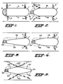
- the holes in the wall of a drainage pipe are preferably not formed exactly radially therein but substantially tangentially on both sides of the pipe, preferably so as to slope inwardly so that it is possible to refer quite legitimately to the outside and the inside of the hole.
- the holes can therefor be regarded as a part having an outside and a part having an inside.
- the right-hand sides of the holes illustrated are the insides and the left-hand sides are the outsides of the holes, the material of the pipe wall also being visible as a result.
- Fig. 1 shows a hole of elongate design with rounded short end edges 1 and 2 for the inside and outside of the hole respectively.
- Long side edges 3 extend between these rounded short end edges 1 and 2.
- tearing occurs at the transition between the long straight side edges 3 and the rounded short end edges 1 and 2. This tearing is referenced 4.
- the rounded portion has no tearing but this does occur where the straight side flanks 3a merge into the rounded portion 2a via oblique flanks 5; tears occur here.
- Attemps were then made to find a hole with no tearing in a plastic pipe, more particularly a plastic drainage pipe having in its wall holes each of elongate form with rounded short end edges and long side edges therebetween.
- a plastic drainage pipe having in its wall holes each of elongate form with rounded short end edges and long side edges therebetween.
- This is made possible according to the present invention by curving the long side edges of the hole continuously, the transverse dimensions of the hole perpendicular to the longitudinal direction of the hole being smaller, near the short rounded end edges, than the transverse dimensions of the hole situated further away from the rounded end edges.
- the plastic pipe may in this case have holes which are oval or elliptical with a continuous radius of curvature of elongate design. This will be explained with reference to the punch for making these holes as illustrated in figs. 6 to 9, the shape of the holes also being shown in fig. 10.
- the side elevation in fig. 6 and the end elevation in fig. 7 show a punch, more particularly a punching knife having a cutting tip for making holes in the wall of a plastic pipe, the effective cross-section of the punch having a large length/width ratio with rounded portions extending in the direction of the width between the side flanks of the punch.
- the length and width of the cross-section of the punch are denoted by letters L and B respectively in figs. 6, 7 and 8.
- the side flanks in the longitudinal direction L of the cross-section are so curved that a tangent 8 extending from one rounded portion 7 to the other rounded portion 7 always contacts the relevant side flank 6 at one point in the cross-sectional plane. With this punch, therefore, it is possible to punch holes having a continuous radius of curvature.
- a descriptive line lla extending from a cross-sectional plane indicated by line 9 to the cutting edge 10 on a curved side flank 6 near a rounded portion 7 is shorter than a similar descritive line 11b further away from the associated rounded portion 7.
- the cross-sectional plane of the operative part of the punch in a practical embodiment is oval-elliptical or approximately elliptical.
- the cutting tip of the punch is also so constructed that a tangent indicated by line 12 extending perpendicularly to the centerline 13 touches the said tip of the punch at a distance from the centerline 13 thereof.
- the punch thus has a knife edge at the flanks at the tip, but the knife edge at each flank extends to a curved line from one rounded portion 7 to the other as will be apparent from fig. 6.
- Each knife edge of the punch also extends to a curved line in the transverse direction (fig. 7).
- the knife edges 10 are formed in known manner by a V-shaped groove in the tip and the resulting cutting edge may be referred to as a fish snout.
- the V-shaped groove extends from one rounded portion to the other and the base of the V-shaped groove has a straight configuration as shown by broken line 14 (fig. 6).
- the base of the V-shaped groove includes an acute angle with a transverse plane extending perpendicularly to the plane of the centerline of the punch, like the tangential plane 12.
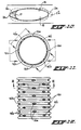
- This elongate hole thus has small rounded portions 2a at the short side produced by the rounded portions 7 of the punch and long continuously curved flanks 15 produced by the flanks 6 of the punch.
- the hole as illustrated in fig. 10 is, for example, a top plan view of the hole 16a (fig. 11) and since this hole is disposed tangentially the wall 2'a of the rounded portion 2a is visible and the hole is therefore regarded as having part of it as the outside.
- the wall 2'b of the opposite rounded portion 2a is not visible and this portion is therefore regarded as the inside.
- burrs may form on the inside of the pipe (reference 17 in fig. 10), but this does not effect the passage shape of the hole.
- the hole according to the present invention accordingly has an invariable passage in the punching direction and this is to the advantage of the water flow when the pipe is used for drainage purposes.
- the holes in the pipe wall are all disposed tangentially, there being simultaneous formation of the holes 16a and and 16b and the holes 16c and 16d diametrically opposite the same.
- the direction of the punches for these holes is offset 45 0 peripherally with respect to the punches for making the holes 16'a and 16'b together with the holes 16'c and 16'd diametrically opposite the same.
- the holes 16a-16d are axially offset with respect to the holes 16'a-16'd.
- the holes 16-16d in this case are situated in one corrugation and the holes 16'a-16'd are situated in the next corrugation. It is not absolutely essential fot two sets of holes always to be formed diametrically with respect to each other. Depending on the required passage characteristics a smaller number of holes may be provided along the periphery, and it is also possible to miss some of the troughs between the corrugations.
- the hole pattern is as illustrated in figs. 11 and 12.
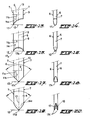
- the holes described do not have to be made just with a cutting punch tip as shown in figs. 6, 8 and 9, but may also be produced by means of a pricking punch tip as illustrated in figs. 13 and 14.
- the cross-section of this latter punch is completely in accordance with fig. 7.
- the rounded portion 7 at the left-hand side in fig. 13 is much longer with respect to the flanks 6 of the tip than the rounded portion 7 on the right-hand side of the punch.
- the punch thus has a rounded but cutting tip 17.
- a descriptive line extending close to the rounded portion 7 from a cross-sectional plane 9 to the tip of the punch is accordingly longer than a descriptive line situated closer to the centerline 13 of the punch.
- These descriptive lines are again referenced 11a and 11b respectively, for the left-hand side of the punch.
- the conditions applicable to the descriptive lines 11a and 11b in fig. 6 again apply to the right-hand side of the punch.
- a pricking punch of this kind can be of a double construction as illustrated in figs. 15 and 16.
- Curved cutting edges 10 are again provided along the flanks 6 by the provision of a V-shaped groove 14b at the end.
- the points 17a and 17b, which contact a tangential plane 12 extending perpendicularly to the centerline 13 of the punch are again at a distance from the centerline 13.
- one central pricking point 17c is provided.at the centerline 13 where it intersects the tangential plane 12.
- the centerlines 11a and 11b again satisfy the conditions described with respect to fig. 6.
- Figs. 19 and 20 show a variant of the punch of figs. 17 and 18.
- the cutting tip is again provided with curved cutting edges 10 but these curved cutting edges are bent at the point 17d.
- the provision of a groove denoted by the line 14c again provides a fish snout for producing the cutting edges 10.
- the cross-section is in accordance with that illustrated in fig. 7 in order ultimately to produce the holes illustrated in fig. 10.
Landscapes
- Engineering & Computer Science (AREA)
- Life Sciences & Earth Sciences (AREA)
- Mechanical Engineering (AREA)
- Forests & Forestry (AREA)
- General Engineering & Computer Science (AREA)
- Agronomy & Crop Science (AREA)
- Civil Engineering (AREA)
- Structural Engineering (AREA)
- Perforating, Stamping-Out Or Severing By Means Other Than Cutting (AREA)
- Rigid Pipes And Flexible Pipes (AREA)
Applications Claiming Priority (2)
| Application Number | Priority Date | Filing Date | Title |
|---|---|---|---|
| NL8203574 | 1982-09-15 | ||
| NL8203574A NL8203574A (nl) | 1982-09-15 | 1982-09-15 | Van gaten voorziene kunststofbuis en ponsnippel voor het aanbrengen van gaten in deze buis. |
Publications (1)
| Publication Number | Publication Date |
|---|---|
| EP0103343A2 true EP0103343A2 (de) | 1984-03-21 |
Family
ID=19840272
Family Applications (1)
| Application Number | Title | Priority Date | Filing Date |
|---|---|---|---|
| EP83201320A Withdrawn EP0103343A2 (de) | 1982-09-15 | 1983-09-13 | Perforiertes Kunststoffrohr und Stanzstempel zum Stanzen der Perforierung |
Country Status (7)
| Country | Link |
|---|---|
| EP (1) | EP0103343A2 (de) |
| JP (1) | JPS5993299A (de) |
| DK (1) | DK420483A (de) |
| ES (1) | ES274566U (de) |
| FI (1) | FI833296L (de) |
| NL (1) | NL8203574A (de) |
| ZA (1) | ZA836840B (de) |
Cited By (3)
| Publication number | Priority date | Publication date | Assignee | Title |
|---|---|---|---|---|
| WO1999011451A1 (de) * | 1997-08-30 | 1999-03-11 | Gaplast Gmbh | Verfahren zur herstellung eines behälters sowie behälter mit druckausgleichsöffnungen |
| EP0958902A3 (de) * | 1998-05-22 | 2000-11-08 | Fuji Photo Film Co., Ltd. | Lochstempel |
| WO2005108775A1 (en) * | 2004-04-28 | 2005-11-17 | Siemens Vdo Automotive Corporation | An asymmetrical punch |
Families Citing this family (1)
| Publication number | Priority date | Publication date | Assignee | Title |
|---|---|---|---|---|
| DE10023801C2 (de) * | 2000-05-15 | 2002-05-23 | Giesecke & Devrient Gmbh | Vorrichtung zum Stanzen von Kunststoffen |
-
1982
- 1982-09-15 NL NL8203574A patent/NL8203574A/nl not_active Application Discontinuation
-
1983
- 1983-09-13 EP EP83201320A patent/EP0103343A2/de not_active Withdrawn
- 1983-09-14 JP JP58168514A patent/JPS5993299A/ja active Pending
- 1983-09-15 DK DK420483A patent/DK420483A/da not_active Application Discontinuation
- 1983-09-15 ZA ZA836840A patent/ZA836840B/xx unknown
- 1983-09-15 ES ES1983274566U patent/ES274566U/es active Pending
- 1983-09-15 FI FI833296A patent/FI833296L/fi not_active Application Discontinuation
Cited By (5)
| Publication number | Priority date | Publication date | Assignee | Title |
|---|---|---|---|---|
| WO1999011451A1 (de) * | 1997-08-30 | 1999-03-11 | Gaplast Gmbh | Verfahren zur herstellung eines behälters sowie behälter mit druckausgleichsöffnungen |
| US6276558B1 (en) * | 1997-08-30 | 2001-08-21 | Gaplast Gmbh | Method for producing a container and container with pressure equalization openings |
| CN1133537C (zh) * | 1997-08-30 | 2004-01-07 | 盖普拉斯特有限公司 | 一种容器的制造方法和具有压力补偿开口的容器 |
| EP0958902A3 (de) * | 1998-05-22 | 2000-11-08 | Fuji Photo Film Co., Ltd. | Lochstempel |
| WO2005108775A1 (en) * | 2004-04-28 | 2005-11-17 | Siemens Vdo Automotive Corporation | An asymmetrical punch |
Also Published As
| Publication number | Publication date |
|---|---|
| JPS5993299A (ja) | 1984-05-29 |
| DK420483A (da) | 1984-03-16 |
| DK420483D0 (da) | 1983-09-15 |
| ZA836840B (en) | 1984-08-29 |
| FI833296A7 (fi) | 1984-03-16 |
| ES274566U (es) | 1984-03-01 |
| FI833296A0 (fi) | 1983-09-15 |
| FI833296L (fi) | 1984-03-16 |
| NL8203574A (nl) | 1984-04-02 |
Similar Documents
| Publication | Publication Date | Title |
|---|---|---|
| KR100567951B1 (ko) | 경막외용 마취침의 외침 | |
| US4351210A (en) | Shear cut tooth | |
| KR860003872A (ko) | 환상캇터 | |
| US3075684A (en) | Easy to open carton | |
| EP0103343A2 (de) | Perforiertes Kunststoffrohr und Stanzstempel zum Stanzen der Perforierung | |
| US2285460A (en) | Screw | |
| KR950007645A (ko) | 낚시바늘과 그 제조방법 | |
| DE3044791A1 (de) | Spanbrecheranordnung fuer schneideinsaetze | |
| JPS5942425B2 (ja) | 絶縁体スライシング端子 | |
| KR100528356B1 (ko) | 관통 개구가 구비된 금속 박 및 벌집체 | |
| JP4542168B2 (ja) | 綜絖及びその製造方法 | |
| US2224532A (en) | Connecting hook for conveyer bands and the like | |
| RU2082906C1 (ru) | Гвоздь | |
| GB2088421A (en) | Perforated sheet material and tubes for fluid filters | |
| GB2106001A (en) | Filter element supports | |
| JPH0744296Y2 (ja) | ナイフの刃 | |
| JPS6047080B2 (ja) | 屑を生ぜしめずに包装ストリップを打抜くための装置 | |
| DE1551294A1 (de) | Druckrohr fuer gekapselte Kaeltemaschinen | |
| DE3566924D1 (en) | Tube of a heat exchanger and procedure of manufacturing of a helix for such a tube | |
| US1768462A (en) | Canada | |
| US3511246A (en) | Perforated pipe and apparatus for making it | |
| US2010444A (en) | Finger ring guard | |
| JPS5835439Y2 (ja) | 厚紙シ−ト切断刃 | |
| US4044636A (en) | Method and apparatus for forming a helical cutter strip for a dry shaver assembly | |
| CA1053988A (en) | Corrugated metal sheet and method for its manufacture |
Legal Events
| Date | Code | Title | Description |
|---|---|---|---|
| PUAI | Public reference made under article 153(3) epc to a published international application that has entered the european phase |
Free format text: ORIGINAL CODE: 0009012 |
|
| AK | Designated contracting states |
Designated state(s): AT BE CH DE FR GB IT LI LU NL SE |
|
| STAA | Information on the status of an ep patent application or granted ep patent |
Free format text: STATUS: THE APPLICATION IS DEEMED TO BE WITHDRAWN |
|
| 18D | Application deemed to be withdrawn |
Effective date: 19860701 |
|
| RIN1 | Information on inventor provided before grant (corrected) |
Inventor name: KOOPMAN, ROELOF |