EP0100698B1 - Siège monocoque à garniture et matelassure intégrées et son procédé de fabrication - Google Patents
Siège monocoque à garniture et matelassure intégrées et son procédé de fabrication Download PDFInfo
- Publication number
- EP0100698B1 EP0100698B1 EP19830401302 EP83401302A EP0100698B1 EP 0100698 B1 EP0100698 B1 EP 0100698B1 EP 19830401302 EP19830401302 EP 19830401302 EP 83401302 A EP83401302 A EP 83401302A EP 0100698 B1 EP0100698 B1 EP 0100698B1
- Authority
- EP
- European Patent Office
- Prior art keywords
- shell
- padding
- inserts
- seat
- mold
- Prior art date
- Legal status (The legal status is an assumption and is not a legal conclusion. Google has not performed a legal analysis and makes no representation as to the accuracy of the status listed.)
- Expired
Links
- 238000004519 manufacturing process Methods 0.000 title claims description 3
- 239000004744 fabric Substances 0.000 claims description 20
- 238000000034 method Methods 0.000 claims description 11
- 239000006260 foam Substances 0.000 claims description 10
- 230000015572 biosynthetic process Effects 0.000 claims description 4
- 238000007664 blowing Methods 0.000 claims description 4
- 238000001125 extrusion Methods 0.000 claims description 3
- 238000009966 trimming Methods 0.000 claims 6
- 238000002844 melting Methods 0.000 claims 1
- 239000011159 matrix material Substances 0.000 description 4
- 239000000463 material Substances 0.000 description 3
- 239000004033 plastic Substances 0.000 description 2
- 229920003023 plastic Polymers 0.000 description 2
- 238000003466 welding Methods 0.000 description 2
- 241001415961 Gaviidae Species 0.000 description 1
- 239000004743 Polypropylene Substances 0.000 description 1
- 229920005830 Polyurethane Foam Polymers 0.000 description 1
- 238000005452 bending Methods 0.000 description 1
- 230000006835 compression Effects 0.000 description 1
- 238000007906 compression Methods 0.000 description 1
- 229920001577 copolymer Polymers 0.000 description 1
- 238000005520 cutting process Methods 0.000 description 1
- 230000003247 decreasing effect Effects 0.000 description 1
- 238000002347 injection Methods 0.000 description 1
- 239000007924 injection Substances 0.000 description 1
- 229920001179 medium density polyethylene Polymers 0.000 description 1
- 239000004701 medium-density polyethylene Substances 0.000 description 1
- 239000000155 melt Substances 0.000 description 1
- 235000011837 pasties Nutrition 0.000 description 1
- -1 polypropylene Polymers 0.000 description 1
- 229920001155 polypropylene Polymers 0.000 description 1
- 239000011496 polyurethane foam Substances 0.000 description 1
- 239000012209 synthetic fiber Substances 0.000 description 1
- 229920002994 synthetic fiber Polymers 0.000 description 1
Images

Classifications
-
- A—HUMAN NECESSITIES
- A47—FURNITURE; DOMESTIC ARTICLES OR APPLIANCES; COFFEE MILLS; SPICE MILLS; SUCTION CLEANERS IN GENERAL
- A47C—CHAIRS; SOFAS; BEDS
- A47C7/00—Parts, details, or accessories of chairs or stools
- A47C7/02—Seat parts
- A47C7/18—Seat parts having foamed material included in cushioning part
- A47C7/185—Seat parts having foamed material included in cushioning part with a stiff, rigid support
Definitions
- the present invention relates to a vehicle seat comprising a shell, a decorative lining, a padding interposed between the shell and the lining, and inserts integral with the shell and used for fixing the seat on the vehicle.
- the padding is placed on the shell while the lining is placed on the padding and fixed by its edges to the shell. Annoying slips between these elements can occur.
- the present invention relates to a seat of the above type, characterized in that the lining, the padding and the inserts are an integral part of the shell, a fastening fabric being interposed between the padding and the shell.
- the present invention also relates to a method of manufacturing this seat.
- This process is characterized in that the padding is formed by injecting a foam between the lining and the hanging fabric, and in that the shell is formed by extrusion and blowing on the hanging fabric.
- the formation of the padding can take place before that of the shell.
- the shell is formed in a mold in which the assembly consisting of the lining, the padding and the hanging fabric has previously been placed.
- the formation of the padding can also take place after that of the shell.
- the shell is formed in a mold in which a cap has been placed consisting of the lining and the hanging fabric previously assembled to one another.
- the inserts can be fixed to the shell by placing these inserts in the bottom of the mold in which the shell is formed. They can also be fixed after formation of the shell by microfusion of the corresponding surfaces of the inserts and of the shell.
- the seat has a padding 1 made of synthetic foam, for example polyurethane foam, which is interposed between an outer lining 2 and a hanging fabric 3, the assembly being an integral part of a blown shell 4 made for example of copolymer polypropylene or of medium density polyethylene.
- the upper part 4a of the seat area of the shell has a decreasing thickness from its longitudinal edge towards the center, thus constituting a flexible fabric accompanying the foam 1 in its crushing and playing the role of elastic base.
- the lower part 4b of this zone has studs 4c which limit the bending of the central portion of this part 4a and limit the sinking of the seat.
- the shell 4 includes inserts used for fixing the seat to the vehicle and made of the same material as the shell, but reinforced with synthetic fibers. In the embodiment shown, these inserts are constituted by an external half-slide 5 and by a plate 6 which is provided on the internal side of the seat and on which supports 7 are fixed for a central slide 8.
- the inserts 5 and 6 are an integral part of the shell.
- the lining 2 and the hanging fabric 3 are made to overflow relative to the padding, as indicated in 2a and 3a.
- the edges of the fabrics 2 and 3 are bonded beforehand by stitching or by high-frequency welding.
- the flexible part thus formed is placed in a mold comprising a matrix 11 and a punch 12, while maintaining the edges 2a and 3a of the fabrics in a sidewall clamp 13 (FIG. 6).
- the exterior profile of the punch 12 corresponds to the exterior profile desired for the exterior face of the shell.
- the profile of the bottom of the matrix 11 corresponds to the profile that takes the external face of the flexible part when it is compressed under a pressure equal to the injection pressure of the shell, for example five bars, its internal face being fixed. This profile is indicated at 14 in Figure 5.
- the die 11 and the punch 12 have on their edges cutting blades 11a and 12a respectively.
- the inserts 5 and 6 are blocked in the mold at the places they must occupy on the shell.
- the shell 4 is then extruded and blown into the mold 11-12.
- the foam 1 is compressed by the blown material in the pasty state until the balance between the blowing pressure and the compression of the foam (FIG. 7).
- the foam 1 On demolding, the blown material being hardened, the foam 1 returns to its initial shape ( Figure 8). The blades 11a and 12a cut the edges of the fabrics 2 and 3 which protruded from the foam. The seat is thus finished and ready to equip a motor vehicle.
- the inserts 5 and 6 can be placed after the shell has been formed by microfusion of the plastic by the mirror process.
- the insert is pressed onto the shell with the interposition of a hot wall, which melts the surfaces of the insert and the shell to the wall upright, this wall is removed and the insert is pressed. on the hull.
- a cap comprising the lining 2 and the attachment fabric 3, the edges of the two fabrics being joined together by stitching and high frequency welding.
- the shell 4 is formed by extrusion and blowing in a mold similar to the mold 11-12 by placing the cover at the bottom of the mold and holding it by the sidewall clamp 13; the profile of this mold corresponds to that desired by the shell.
- the inserts 5 and 6 are placed on the shell by microfusion of the plastic by the mirror process. It only remains to inject the synthetic foam 1 between the lining 2 and the attachment fabric 3 in a mold comprising a matrix 15 and a punch 15 (FIG. 9).
- the profile of the die 15 is that of the external shape desired for the padding 1 while the punch 16 has the shape of the outside face of the shell 4.
Landscapes
- Seats For Vehicles (AREA)
- Casting Or Compression Moulding Of Plastics Or The Like (AREA)
Description
- La présente invention a pour objet un siège de véhicule comportant une coque, une garniture décorative, une matelassure interposée entre la coque et la garniture, et des inserts solidaires de la coque et servant à la fixation du siège sur le véhicule.
- Dans les sièges de ce genre jusqu'à présent fabriqués, la matelassure est posée sur la coque alors que la garniture est posée sur la matelassure et fixée par ses bords à la coque. Des glissements gênants entre ces éléments peuvent se produire.
- La présente invention a pour objet un siège du type ci-dessus, caractérisée en ce que la garniture, la matelassure et les inserts font partie intégrante de la coque, un tissu d'accrochage étant interposé entre la matelassure et la coque.
- La présente invention a également pour objet un procédé de fabrication de ce siège.
- Ce procédé est caractérisé en ce qu'on forme la matelassure par injection d'une mousse entre la garniture et le tissu d'accrochage, et en ce qu'on forme la coque par extrusion et soufflage sur le tissu d'accrochage.
- La formation de la matelassure peut avoir lieu avant celle de la coque. Dans ce cas, on forme la coque dans un moule dans lequel on a préalablement placé l'ensemble constitué par la garniture, la matelassure et le tissu d'accrochage.
- La formation de la matelassure peut également avoir lieu après celle de la coque. Dans ce cas, on forme la coque dans un moule dans lequel on a placé une coiffe constituée par la garniture et le tissu d'accrochage préalablement assemblés l'un à l'autre.
- On peut fixer les inserts à la coque en disposant ces inserts dans le fond du moule dans lequel la coque est formée. On peut également les fixer après formation de la coque par microfusion des surfaces correspondantes des inserts et de la coque.
- On a décrit ci-après, à titre d'exemples non limitatifs, un mode de réalisation du siège selon l'invention et des modes de mise en oeuvre du procédé permettant de le réaliser, avec référence aux dessins annexés dans lesquels :
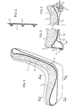
- La figure 1 est une vue en coupe longitudinale médiane du siège ;
- La figure 2 en est une demi-coupe transversale suivant II-II de la figure 1 ;
- La figure 3 en est une demi-coupe transversale suivant III-III de la figure 1 ;
- La figure 4 est une coupe suivant IV-IV de la figure 3 ;
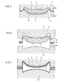
- Les figures 5 à 8 sont des vues en coupe transversale montrant diverses étapes du procédé, dans un premier mode de mise en oeuvre ;
- La figure 9 est une vue en coupe transversale montrant un second mode de mise en oeuvre du procédé.
- Tel qu'il est représenté au dessin, le siège comporte une matelassure 1 en mousse synthétique, par exemple en mousse de polyuréthane, qui est interposée entre une garniture extérieure 2 et un tissu d'accrochage 3, l'ensemble faisant partie intégrante d'une coque soufflée 4 réalisée par exemple en polypropylène copolymère ou en polyéthylène de densité moyenne. La partie supérieure 4a de la zone d'assise de la coque a une épaisseur dégressive depuis son bord longitudinal vers le centre, en constituant ainsi une toile souple accompagnant la mousse 1 dans son écrasement et jouant le rôle de sommier élastique. La partie inférieure 4b de cette zone comporte des plots 4c qui limitent la flexion de la portion centrale de cette partie 4a et limitent l'enfoncement de l'assise. La coque 4 comporte des inserts servant à la fixation du siège sur le véhicule et réalisée en la même matière que la coque, mais renforcés par des fibres synthétiques. Dans l'exemple de réalisation représenté, ces inserts sont constitués par une demi-glissière extérieure 5 et par une plaquette 6 qui est prévue sur le côté intérieur de l'assise et sur laquelle sont fixés des supports 7 pour une glissière centrale 8.
- De même que la garniture extérieure 2 et la matelassure 1, les inserts 5 et 6 font partie intégrante de la coque.
- A cet effet, on peut commencer par former la partie souple de l'assise et du dossier du siège en injectant la mousse 1 entre la garniture 2 et le tissu d'accrochage 3, dans un moule qui comprend une matrice 9 et un poinçon 10 et dont le profil est celui du profil extérieur désiré pour la matelassure (figure 5).
- On fait déborder la garniture 2 et le tissu d'accrochage 3 par rapport à la matelassure, comme indiqué en 2a et 3a. La liaison des bords des tissus 2 et 3 est assurée au préalable par- piquage ou par soudage à haute fréquence.
- Puis on place la partie souple ainsi formée dans un moule comprenant une matrice 11 et un poinçon 12, en maintenant les bords 2a et 3a des tissus dans un serre-flanc 13 (figure 6). Le profil extérieur du poinçon 12 correspond au profil extérieur désiré pour la face extérieure de la coque. Le profil du fond de la matrice 11 correspond au profil que prend la face extérieure de la partie souple quand on la comprime sous une pression égale à la pression d'injection de la coque, par exemple cinq bars, sa face intérieure étant fixe. Ce profil est indiqué en 14 à la figure 5. La matrice 11 et le poinçon 12 comportent sur leurs bords des lames de coupe respectivement 11a et 12a. On bloque les inserts 5 et 6 dans le moule aux endroits qu'ils doivent occuper sur la coque.
- On procède alors à l'extrusion et au soufflage de la coque 4 dans le moule 11-12. La mousse 1 est comprimée par la matière soufflée à l'état pâteux jusqu'à l'équilibre entre la pression de soufflage et la compression de la mousse (figure 7).
- Au démoulage, la matière soufflée étant durcie, la mousse 1 reprend sa forme initiale (figure 8). Les lames 11 a et 12a ont coupé les bords des tissus 2 et 3 qui faisaient saillie par rapport à la mousse. Le siège est ainsi terminé et prêt à équiper un véhicule automobile.
- En variante, on peut poser les inserts 5 et 6 après formation de la coque par microfusion de la matière plastique par le procédé au miroir. A cet effet, on presse l'insert sur la coque avec interposition d'une paroi chaude, ce qui fait fondre les surfaces de l'insert et de la coque au montant de la paroi, on retire cette paroi et on presse l'insert sur la coque.
- On peut également former d'abord une coiffe comprenant le garnissage 2 et le tissu d'accrochage 3, les bords des deux tissus étant réunis par piquage et soudage à haute fréquence. Puis on forme la coque 4 par extrusion et soufflage dans un moule analogue au moule 11-12 en plaçant la coiffe au fond du moule et en la maintenant par le serre-flanc 13 ; le profil de ce moule correspond à celui désiré par la coque. On pose les inserts 5 et 6 sur la coque par microfusion de la matière plastique par le procédé au miroir. Il ne reste plus qu'à injecter la mousse synthétique 1 entre la garniture 2 et le tissu d'accrochage 3 dans un moule comprenant une matrice 15 et un poinçon 15 (figure 9). Le profil de la matrice 15 est celui de la forme extérieure désirée pour la matelassure 1 alors que le poinçon 16 a la forme de la face extérieure de la coque 4.
Claims (6)
Applications Claiming Priority (2)
| Application Number | Priority Date | Filing Date | Title |
|---|---|---|---|
| FR8212149 | 1982-07-06 | ||
| FR8212149A FR2529842A1 (fr) | 1982-07-06 | 1982-07-06 | Siege monocoque a garniture et matelassure integrees et son procede de fabrication |
Publications (3)
| Publication Number | Publication Date |
|---|---|
| EP0100698A2 EP0100698A2 (fr) | 1984-02-15 |
| EP0100698A3 EP0100698A3 (en) | 1985-04-10 |
| EP0100698B1 true EP0100698B1 (fr) | 1987-03-25 |
Family
ID=9275883
Family Applications (1)
| Application Number | Title | Priority Date | Filing Date |
|---|---|---|---|
| EP19830401302 Expired EP0100698B1 (fr) | 1982-07-06 | 1983-06-23 | Siège monocoque à garniture et matelassure intégrées et son procédé de fabrication |
Country Status (3)
| Country | Link |
|---|---|
| EP (1) | EP0100698B1 (fr) |
| DE (1) | DE3370439D1 (fr) |
| FR (1) | FR2529842A1 (fr) |
Families Citing this family (5)
| Publication number | Priority date | Publication date | Assignee | Title |
|---|---|---|---|---|
| DE3421078A1 (de) * | 1983-06-28 | 1985-02-07 | Aisin Seiki K.K., Kariya, Aichi | Fahrzeugsitz |
| IT212716Z2 (it) | 1987-10-29 | 1989-08-28 | Stars Spa | Struttura di sedile particolarmente per autoveicoli costituito da una struttura di materiale plastico e riporto morbido a rapido assemblaggio |
| DE19736839A1 (de) * | 1997-08-23 | 1999-02-25 | Volkswagen Ag | Deformationsstruktur für den Insassenschutz in Fahrzeugen |
| DE102010036798B4 (de) * | 2010-08-02 | 2022-09-29 | Kokinetics Gmbh | Sitzteil |
| DE102022122623A1 (de) * | 2022-09-06 | 2024-03-07 | Kristof Hock | "Sitzeinrichtung mit einem mit Luft gefüllten Sitzkissen" |
Family Cites Families (2)
| Publication number | Priority date | Publication date | Assignee | Title |
|---|---|---|---|---|
| GB998571A (en) * | 1960-11-09 | 1965-07-14 | Parker Knoll Ltd | Improvements in or relating to upholstery |
| FR1496282A (fr) * | 1966-10-07 | 1967-09-29 | Siège moulé et procédé pour sa fabrication |
-
1982
- 1982-07-06 FR FR8212149A patent/FR2529842A1/fr active Granted
-
1983
- 1983-06-23 DE DE8383401302T patent/DE3370439D1/de not_active Expired
- 1983-06-23 EP EP19830401302 patent/EP0100698B1/fr not_active Expired
Also Published As
| Publication number | Publication date |
|---|---|
| EP0100698A2 (fr) | 1984-02-15 |
| EP0100698A3 (en) | 1985-04-10 |
| DE3370439D1 (en) | 1987-04-30 |
| FR2529842A1 (fr) | 1984-01-13 |
| FR2529842B1 (fr) | 1984-12-21 |
Similar Documents
| Publication | Publication Date | Title |
|---|---|---|
| KR960012609B1 (ko) | 자동차 시이트의 제조방법 | |
| US5788332A (en) | Seat unit and cushion | |
| KR910005201B1 (ko) | 혼성제품 성형 방법 | |
| FR2627427A1 (fr) | Procede de fabrication de sieges moules integralement en mousse | |
| EP0517615A1 (fr) | Procédé de moulage d'un coussin apte à constituer un insert d'un siège, coussin ainsi obtenu et siège le comportant | |
| FR2482255A1 (fr) | Armatures de sieges ou plaques de separation pour vehicules realisees en resine synthetique et leur procede de fabrication | |
| EP1689571B1 (fr) | Procede de fabrication de supports elastiques monoblocs et supports ainsi obtenus | |
| TW503089B (en) | Method of making an injection molded luggage shell and luggage case made therefrom | |
| JPH1035366A (ja) | 車輛用物品キャリヤの側部レール及びその製造方法 | |
| EP0100698B1 (fr) | Siège monocoque à garniture et matelassure intégrées et son procédé de fabrication | |
| JP2000500670A (ja) | 固定されたカバーを有する室内装飾要素及びその製造方法 | |
| FR2598967A1 (fr) | Procede de fabrication de matelassures moulees en mousse de polyurethane comportant plusieurs zones de souplesses differentes et matelassures ainsi realisees | |
| FR2635513A1 (fr) | Procede et dispositif de realisation de coussins recouverts d'une enveloppe et destines a equiper un siege | |
| JPS59189890A (ja) | 一体成形座席用表皮及びそれを用いた座席の製造方法 | |
| JP2000004992A (ja) | 座または背凭れ等の椅子の構造物の製造方法 | |
| FR2737991A1 (fr) | Siege a maintiens lateraux pour automobile | |
| FR2635515A1 (fr) | Procede de realisation d'un coussin recouvert d'une enveloppe, destine a equiper un siege | |
| FR2868004A1 (fr) | Coussin en mousse revetu d'une coiffe d'habillage, son outillage et son procede de fabrication | |
| JP3752001B2 (ja) | 自動車用ヘッドレスト | |
| FR2956347A1 (fr) | Procede de realisation par moulage et decoupe, de structures d'accrochage dans un corps de siege en matiere plastique soufflee. | |
| EP1433585A2 (fr) | Panneau comportant un cadre et procédé de fabrication | |
| FR2956346A1 (fr) | Procede de realisation par moulage et poinconnage, de structures d'accrochage dans un corps de siege en matiere plastique soufflee | |
| EP0954426A1 (fr) | Procede d'insertion de decors dans une piece thermoplastique | |
| WO2009034257A2 (fr) | Élément de garnissage de siège de véhicule automobile comprenant un bloc en polyoléfine expansée à face d'aspect grainée | |
| FR2621284A1 (fr) | Appuie-tete pour sieges de vehicules, notamment de vehicules automobiles |
Legal Events
| Date | Code | Title | Description |
|---|---|---|---|
| PUAI | Public reference made under article 153(3) epc to a published international application that has entered the european phase |
Free format text: ORIGINAL CODE: 0009012 |
|
| AK | Designated contracting states |
Designated state(s): DE GB IT |
|
| PUAL | Search report despatched |
Free format text: ORIGINAL CODE: 0009013 |
|
| AK | Designated contracting states |
Designated state(s): DE GB IT |
|
| 17P | Request for examination filed |
Effective date: 19850312 |
|
| 17Q | First examination report despatched |
Effective date: 19860219 |
|
| GRAA | (expected) grant |
Free format text: ORIGINAL CODE: 0009210 |
|
| AK | Designated contracting states |
Kind code of ref document: B1 Designated state(s): DE GB IT |
|
| ITF | It: translation for a ep patent filed | ||
| REF | Corresponds to: |
Ref document number: 3370439 Country of ref document: DE Date of ref document: 19870430 |
|
| REG | Reference to a national code |
Ref country code: GB Ref legal event code: 746 |
|
| PLBE | No opposition filed within time limit |
Free format text: ORIGINAL CODE: 0009261 |
|
| STAA | Information on the status of an ep patent application or granted ep patent |
Free format text: STATUS: NO OPPOSITION FILED WITHIN TIME LIMIT |
|
| 26N | No opposition filed | ||
| ITTA | It: last paid annual fee | ||
| PGFP | Annual fee paid to national office [announced via postgrant information from national office to epo] |
Ref country code: GB Payment date: 19960618 Year of fee payment: 14 |
|
| PGFP | Annual fee paid to national office [announced via postgrant information from national office to epo] |
Ref country code: DE Payment date: 19960619 Year of fee payment: 14 |
|
| PG25 | Lapsed in a contracting state [announced via postgrant information from national office to epo] |
Ref country code: GB Free format text: LAPSE BECAUSE OF NON-PAYMENT OF DUE FEES Effective date: 19970623 |
|
| GBPC | Gb: european patent ceased through non-payment of renewal fee |
Effective date: 19970623 |
|
| PG25 | Lapsed in a contracting state [announced via postgrant information from national office to epo] |
Ref country code: DE Free format text: LAPSE BECAUSE OF NON-PAYMENT OF DUE FEES Effective date: 19980303 |