EP0100397B1 - Adaptateur pour cassette à bande magnétique - Google Patents
Adaptateur pour cassette à bande magnétique Download PDFInfo
- Publication number
- EP0100397B1 EP0100397B1 EP83103656A EP83103656A EP0100397B1 EP 0100397 B1 EP0100397 B1 EP 0100397B1 EP 83103656 A EP83103656 A EP 83103656A EP 83103656 A EP83103656 A EP 83103656A EP 0100397 B1 EP0100397 B1 EP 0100397B1
- Authority
- EP
- European Patent Office
- Prior art keywords
- adapter
- cassette
- minicassette
- cover
- adapter according
- Prior art date
- Legal status (The legal status is an assumption and is not a legal conclusion. Google has not performed a legal analysis and makes no representation as to the accuracy of the status listed.)
- Expired
Links
- 238000004804 winding Methods 0.000 claims description 16
- 230000000903 blocking effect Effects 0.000 claims description 6
- 230000006835 compression Effects 0.000 claims description 2
- 238000007906 compression Methods 0.000 claims description 2
- 238000000605 extraction Methods 0.000 claims 3
- 238000000034 method Methods 0.000 description 6
- 230000002441 reversible effect Effects 0.000 description 5
- 230000008878 coupling Effects 0.000 description 2
- 238000010168 coupling process Methods 0.000 description 2
- 238000005859 coupling reaction Methods 0.000 description 2
- 230000001419 dependent effect Effects 0.000 description 2
- 230000001960 triggered effect Effects 0.000 description 2
- 230000006978 adaptation Effects 0.000 description 1
- 230000005540 biological transmission Effects 0.000 description 1
- 239000000969 carrier Substances 0.000 description 1
- 238000010276 construction Methods 0.000 description 1
- 238000013016 damping Methods 0.000 description 1
- 238000011161 development Methods 0.000 description 1
- 230000018109 developmental process Effects 0.000 description 1
- 238000005516 engineering process Methods 0.000 description 1
- 238000003780 insertion Methods 0.000 description 1
- 230000037431 insertion Effects 0.000 description 1
Images
Classifications
-
- G—PHYSICS
- G11—INFORMATION STORAGE
- G11B—INFORMATION STORAGE BASED ON RELATIVE MOVEMENT BETWEEN RECORD CARRIER AND TRANSDUCER
- G11B23/00—Record carriers not specific to the method of recording or reproducing; Accessories, e.g. containers, specially adapted for co-operation with the recording or reproducing apparatus ; Intermediate mediums; Apparatus or processes specially adapted for their manufacture
- G11B23/02—Containers; Storing means both adapted to cooperate with the recording or reproducing means
- G11B23/04—Magazines; Cassettes for webs or filaments
- G11B23/08—Magazines; Cassettes for webs or filaments for housing webs or filaments having two distinct ends
- G11B23/087—Magazines; Cassettes for webs or filaments for housing webs or filaments having two distinct ends using two different reels or cores
-
- G—PHYSICS
- G11—INFORMATION STORAGE
- G11B—INFORMATION STORAGE BASED ON RELATIVE MOVEMENT BETWEEN RECORD CARRIER AND TRANSDUCER
- G11B25/00—Apparatus characterised by the shape of record carrier employed but not specific to the method of recording or reproducing, e.g. dictating apparatus; Combinations of such apparatus
- G11B25/06—Apparatus characterised by the shape of record carrier employed but not specific to the method of recording or reproducing, e.g. dictating apparatus; Combinations of such apparatus using web-form record carriers, e.g. tape
- G11B25/066—Apparatus characterised by the shape of record carrier employed but not specific to the method of recording or reproducing, e.g. dictating apparatus; Combinations of such apparatus using web-form record carriers, e.g. tape adapted for use with containers of different sizes or configurations; adaptor devices therefor
Definitions
- the invention relates to a container for holding a mini magnetic tape cassette in a video device suitable for a standardized reversible cassette of a certain video system, the mini cassette consisting of two half parts which can be displaced in the main direction of extension of the cassette and can be locked in the starting position, and that the container two has symmetrically arranged swivel arms with tape guide elements which engage behind the magnetic tape of the mini-cassette in the starting position and bring it into a position corresponding to the standardized cassette within the container.
- cassettes with two tape reels arranged next to one another are preferably used as magnetic tape carriers in modern devices for sound and image recording, the obvious requirement arises that cassettes which are as small as possible are to be used in particular in portable devices.
- the user of such devices desires that the tape volume enables the longest possible playing time.
- the object of the invention is to provide a container for receiving a pull-out mini-cassette of the above-described embodiment, which fulfills all the functions required to be able to use a mini-cassette in a home device in a very simple manner, according to one for standardized reversible cassettes suitable video system works.
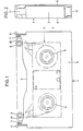
- Fig. 1 shows a container 1 for receiving a mini magnetic tape cassette 2, which is shown in dash-dotted lines in the figure shown.
- the outer dimensions of the container correspond to a standardized reversible cassette which is suitable for a video device of a specific video system.
- a small cassette for portable devices can be played in a home device that is suitable for a larger cassette with a long playing time.
- the magnetic tape of the inserted mini-cassette 2 (shown in dash-dotted lines in the figure) assumes the starting position in the container, which is required to pick up the magnetic tape from the normal position required in home appliances by means of the device's own tape transport means and to pull it out of the container or the mini-cassette.
- the container for holding the mini-cassette consists of a rectangular frame part 3 with an integrally connected base plate 4 and a pivotable cover 5.
- the frame 3 is continuously open on a long side 6, ie the magnetic tape can be led out from this side.
- the lid 5 is connected on both outer sides via a joint 7 to the short side legs of the frame.
- two tape guide elements 9, 9 ' one of which is arranged on its own swivel arm 10, 10', the magnetic tape is standardized into that of the appropriate cassette.
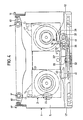
- the container 1 can be seen in the side view and shows the frame 3 with base plate 4 and the cover 5 extending over the frame.
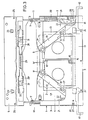
- Fig. 3 shows the container 1 in the open state when inserting the closed mini-cassette, the position of which is indicated by dash-dotted lines in its outer contours.
- the lid 5 of the opened container is completely folded back, and the mini-cassette 2 can thus be inserted without difficulty.
- the two side slides 12, 12 'must be pulled out of the container at the same time until a noticeable stop.
- the sideshift locks in the pulled-out position and remains in this position. In this process, the lid lock is released at the same time, and the lid can be opened or it is raised independently by means of a torsion spring.
- the tape guide elements 9.9 ' which are mounted on the swivel arms 10, 10' assigned to them, assume the starting position swung inwards for the insertion of the mini-cassette.
- the two swivel arms 10, 10 ' are controlled by a sliding plate 13, 13' inserted in the base plate 4 of the container.
- the two sliding plates are guided on both sides on their long sides in the floor and each have a recess in their center for receiving the cassette winding spools, the winding spools engaging in the recesses with a guide flange.
- notches and projections spanning the outer sides 14, 14 ' are provided such that a centering pin 15, 15' is to be arranged on the center line of the container on each of these.
- the centering pins are used to determine the exact position when inserting a mini-cassette into the container and simultaneously unlock the two half-cassettes.
- the side slides are each in engagement with the opposite sliding plate, so that, for. B. when pulling out the right side slider 12 according to the drawing, the left sliding plate 13 'is pushed towards the center into the starting position and vice versa.
- Both sliding plates each have a driving pin 16, 16 'which engages in a longitudinal slot 17, 17' of the swivel arm assigned to the respective sliding plate side.
- the swivel arms are each rotatably supported by a bearing pin 18 which is arranged in the frame 3 of the container.
- the rectangular frame 3 is closed with a partial cover 19.
- the partial cover 19 is shown broken on the shorter leg of the rectangular frame part 3 and thus reveals an inner part of the frame.
- the locking slide 11 with compression spring 20, which can be recognized in its entire function as a result, is immersed in the frame 3 of the housing when the container is inserted into a home appliance and actuates a locking pawl 22 via a run-up slope 21, which pawl 18 on the bearing pin 18 together with the swivel arm 10 is stored.
- the lid 5 which is shown in broken form for reasons of simple illustration, has on the inner side facing away from the pivot point of the joint 7 two symmetrically arranged latching hooks 23, 23 ', which serve to lock the lid by the side slides in the closed state of the container .
- the latching hooks 23, 23 ' engage in assigned rectangular cutouts 24, 24' of the frame 3 or the partial cover 19.
- the side slides are closed when the lid is closed by two vertically protruding pins 25, which are located in the lid on both sides near the latching hooks 25 'triggered, as soon as the pins dip into the cutouts 26, 26' assigned to the frame during the lid closing process, the detent pawls 27, 27 'blocking the side slides are hereby triggered.
- the unlocking slides 28, 28 ' have locking lugs 31, 31', each of which engages in a cutout in the half part of a mini-cassette inserted in the housing when the cover is closed, and cancels the coil lock assigned to the mini-cassette.
- the unlocking slides 28, 28 ' move with the extendable or pluggable half parts of the mini-cassette.
- the frame part receiving the side slider and opposite the free band exit is shown broken away, the housing being drawn in the closed state and the inserted mini cassette being indicated by dash-dotted lines.
- the two side slides 12, 12 ' have in the inner frame part of the housing area a part which is designed as a toothed rack 32, 32' and overlaps at different levels and the two toothed rack parts engage together to form a coupling gearwheel 33 which is fixedly mounted in the middle of the lower frame part stand. This ensures that both side shifters cover the same distances when actuated, or even when only one side shifter is actuated, the sliding plates 13, 13 'and swivel arms 10, 10' connected to them are always pivoted simultaneously and in the same way.
- the coupling gear 33 connecting the rack part of the side shifters has one Damping device that only works in one direction of rotation.
- the rack part of the left side slide 12 'connected to the right sliding plate 13 according to the position of the drawing carries a bearing plate 34 which is mounted on an axis of rotation 35 and is partially pivotable.
- a gear 36 is arranged on the bearing plate and can be brought into engagement with a spool flange 38 of a winding body of the inserted mini-cassette provided with saw teeth via a driving wheel 37.
- the gear 36 consists of a double gear 39 which engages with the rack part of the right side slider 12 via a gear stage and drives a further double gear with the other gear stage via an idler gear which is designed as a driving gear 37 for the spool flange 38 of the mini-cassette .
- the bearing plate 34 and thus the gear 36 is brought into engagement position by a tension spring.
- the gearbox, i.e. H. the driving wheel 37 and the toothed coil flange 38 of the mini-cassette remain engaged until the mini-cassette has almost reached its assembled starting position due to the opening process of the container.
- a siphon 40 attached to the right-hand side slide 12 or rack part strikes the bearing plate 34 of the transmission and removes the engagement of the driving wheel 37 in the spool flange 38 of the mini-cassette.
- the two side slides 12, 12 ' are connected to a tension spring 41.
- This tension spring acts as an energy accumulator, which is pulled up by pulling out the side slides and ensures that all necessary movement functions run automatically when the lid is closed.
- the housing cover of the container can only be opened after the two side slides have been pulled out. These snap into their end positions and the cover of the housing can be opened.
- the mini cassette can be placed in the container. Guide tabs on the mini-cassette ensure the correct position of the cassette in the container. When inserting the cassette, the centering pins in the housing dip into the cassette and unlock the two half parts of the cassette. At the same time, the half parts of the cassette are anchored on the sliding plates.
- the locking lugs of the unlocking slides in the lid dip into corresponding recesses in the mini-cassette and release the winding spool lock of the cassette.
- the side shifters are unlocked and the half-parts of the mini-cassette are pulled apart by means of an energy store in the housing and brought to the required center distance, which is required for the tape winding drive in the home device.
- the swivel arms with the tape guide elements simultaneously bring the magnetic tape into the position required by the standard cassette. This overall process takes place in a dampened manner by taking appropriate precautions.
- the pawls of the locking slides engage on both sides through a slot in the half parts of the cassette and prevent the magnetic tape from becoming loose.
- the container with the mini cassette can now be handled like a standard reversible cassette for the home device.
- the locking of the winding spools is released by the pawl in the container, and the magnetic tape is free.
- the gear is brought and brought into engagement with a driving wheel on a spool flange with teeth on the spool body of the mini-cassette.
- the gear is driven by engagement with a rack part of a side slider and thus winds up the excess magnetic tape that results from the pushing together of the two cassette half parts.
- the gearbox is returned to its starting position and anchored there by the siphon before the cover is opened.
- the latch of the lid lock is released, the lid can be opened and the mini-cassette can be removed.
Landscapes
- Packaging Of Annular Or Rod-Shaped Articles, Wearing Apparel, Cassettes, Or The Like (AREA)
- Coating Apparatus (AREA)
Claims (12)
Priority Applications (1)
| Application Number | Priority Date | Filing Date | Title |
|---|---|---|---|
| AT83103656T ATE29081T1 (de) | 1982-06-09 | 1983-04-15 | Behaelter zur aufnahme einer magnetbandkassette. |
Applications Claiming Priority (2)
| Application Number | Priority Date | Filing Date | Title |
|---|---|---|---|
| DE3221761 | 1982-06-09 | ||
| DE19823221761 DE3221761A1 (de) | 1982-06-09 | 1982-06-09 | Behaelter zur aufnahme einer magnetbandkassette |
Publications (2)
| Publication Number | Publication Date |
|---|---|
| EP0100397A1 EP0100397A1 (fr) | 1984-02-15 |
| EP0100397B1 true EP0100397B1 (fr) | 1987-08-19 |
Family
ID=6165714
Family Applications (1)
| Application Number | Title | Priority Date | Filing Date |
|---|---|---|---|
| EP83103656A Expired EP0100397B1 (fr) | 1982-06-09 | 1983-04-15 | Adaptateur pour cassette à bande magnétique |
Country Status (5)
| Country | Link |
|---|---|
| US (1) | US4492351A (fr) |
| EP (1) | EP0100397B1 (fr) |
| JP (1) | JPS592271A (fr) |
| AT (1) | ATE29081T1 (fr) |
| DE (2) | DE3221761A1 (fr) |
Families Citing this family (6)
| Publication number | Priority date | Publication date | Assignee | Title |
|---|---|---|---|---|
| EP0153137B1 (fr) * | 1984-02-16 | 1990-11-28 | Matsushita Electric Industrial Co., Ltd. | Cassette de bande pour enregistrement de courte durée |
| JPH0640413B2 (ja) * | 1985-09-23 | 1994-05-25 | ソニー株式会社 | デイスクカ−トリツジのシヤツタ開閉機構 |
| US5021903A (en) * | 1988-06-24 | 1991-06-04 | Rank Video Services America | Magnetic tape cartridge |
| US4964003A (en) * | 1988-06-24 | 1990-10-16 | Rank Video Services America | Tape interconnection system |
| US4920436A (en) * | 1988-06-24 | 1990-04-24 | Rank Video Services America | Magnetic tape cassette system |
| US6305631B1 (en) | 1999-09-28 | 2001-10-23 | Imation Corp. | Tape cartridge with remove to operate tape and hubs |
Citations (1)
| Publication number | Priority date | Publication date | Assignee | Title |
|---|---|---|---|---|
| EP0077876A1 (fr) * | 1981-10-27 | 1983-05-04 | GRUNDIG E.M.V. Elektro-Mechanische Versuchsanstalt Max Grundig holländ. Stiftung & Co. KG. | Minicassette |
Family Cites Families (10)
| Publication number | Priority date | Publication date | Assignee | Title |
|---|---|---|---|---|
| US3701495A (en) * | 1970-08-10 | 1972-10-31 | Xerox Corp | Expandable cassette |
| US3955779A (en) * | 1974-05-28 | 1976-05-11 | Bell & Howell Company | Cartridge with removable take-up sub-cartridge |
| DE2518762A1 (de) * | 1975-04-26 | 1976-11-04 | Agfa Gevaert Ag | Mehrteilige filmkassette |
| JPS5291407A (en) * | 1976-01-27 | 1977-08-01 | Sony Corp | Cassette mounting device for recorder/reproducer units |
| JPS586218B2 (ja) * | 1975-12-23 | 1983-02-03 | オリンパス光学工業株式会社 | テ−プカセツト |
| US4092686A (en) * | 1976-02-17 | 1978-05-30 | Odetics, Inc. | Tape withdrawal and tensioning mechanism for video cassette recorder/reproducer |
| JPS5855577B2 (ja) * | 1976-08-16 | 1983-12-10 | 松下電器産業株式会社 | 磁気テ−プ装置 |
| DE2713470A1 (de) * | 1977-03-26 | 1978-09-28 | Bosch Gmbh Robert | Geraet zur aufzeichnung und/oder wiedergabe von informationen auf bandfoermigen aufzeichnungstraeger |
| JPS595978B2 (ja) * | 1978-09-22 | 1984-02-08 | 松下電器産業株式会社 | 磁気テ−プ収納器 |
| JPS57123573A (en) * | 1981-01-20 | 1982-08-02 | Victor Co Of Japan Ltd | Adapter for tape cassette |
-
1982
- 1982-06-09 DE DE19823221761 patent/DE3221761A1/de not_active Withdrawn
-
1983
- 1983-04-15 EP EP83103656A patent/EP0100397B1/fr not_active Expired
- 1983-04-15 DE DE8383103656T patent/DE3373157D1/de not_active Expired
- 1983-04-15 AT AT83103656T patent/ATE29081T1/de not_active IP Right Cessation
- 1983-06-09 JP JP58101853A patent/JPS592271A/ja active Pending
- 1983-06-09 US US06/502,467 patent/US4492351A/en not_active Expired - Fee Related
Patent Citations (1)
| Publication number | Priority date | Publication date | Assignee | Title |
|---|---|---|---|---|
| EP0077876A1 (fr) * | 1981-10-27 | 1983-05-04 | GRUNDIG E.M.V. Elektro-Mechanische Versuchsanstalt Max Grundig holländ. Stiftung & Co. KG. | Minicassette |
Also Published As
| Publication number | Publication date |
|---|---|
| ATE29081T1 (de) | 1987-09-15 |
| US4492351A (en) | 1985-01-08 |
| DE3373157D1 (en) | 1987-09-24 |
| DE3221761A1 (de) | 1983-12-15 |
| JPS592271A (ja) | 1984-01-07 |
| EP0100397A1 (fr) | 1984-02-15 |
Similar Documents
| Publication | Publication Date | Title |
|---|---|---|
| DE3201598C2 (fr) | ||
| DE3244797C2 (fr) | ||
| DE4231574C2 (de) | Ladevorrichtung für Bandkassetten | |
| DE4445834A1 (de) | Magnetisches Aufzeichnungs- und Wiedergabegerät mit Spielpakettreiber | |
| DE3146594C2 (de) | Kleinvideokassette und zugehöriger Adapter | |
| EP0100397B1 (fr) | Adaptateur pour cassette à bande magnétique | |
| DE69124405T2 (de) | Ladevorrichtung für Kassetten | |
| EP0234660B1 (fr) | Appareil d'enregistrement et/ou de reproduction | |
| DE3327599C2 (de) | Adapter für eine Miniaturbandkassette | |
| EP0077876B1 (fr) | Minicassette | |
| DE2536274A1 (de) | Lade-/entlade-einrichtung fuer ein magnetbandlaufwerk nach dem kontaktwickelprinzip | |
| DE69016497T2 (de) | Von oben geladene Bandkassette für Videokassette. | |
| DE69024575T2 (de) | Kassettenbehälter für Bandwiedergabegerät | |
| EP0322056B1 (fr) | Appareil d'enregistrement et/ou de reproduction pour un support d'information en forme de bande | |
| DE69116589T2 (de) | Bandkassetten | |
| DE69016233T2 (de) | Lademechanismus für ein Aufzeichnungs-/Wiedergabegerät. | |
| DE3924107C2 (fr) | ||
| EP0463320B1 (fr) | Récipient pour cassettes à bande magnétique | |
| EP0610270B1 (fr) | Dispositif de chargement de cassettes | |
| AT379465B (de) | Bandkassette | |
| DE3239892A1 (de) | Video-wendekassette | |
| DE69122443T2 (de) | Bandkassette | |
| DE2023390A1 (de) | Einrichtung zur Abnahme eines Bandes | |
| DE2103659C2 (de) | Kassetten-Kleindiktiergerät | |
| DE19634475C2 (de) | Vorrichtung zur Bildstandsicherung bei Mehrfachbelichtung |
Legal Events
| Date | Code | Title | Description |
|---|---|---|---|
| PUAI | Public reference made under article 153(3) epc to a published international application that has entered the european phase |
Free format text: ORIGINAL CODE: 0009012 |
|
| AK | Designated contracting states |
Designated state(s): AT BE CH DE FR GB IT LI |
|
| 17P | Request for examination filed |
Effective date: 19840816 |
|
| RAP1 | Party data changed (applicant data changed or rights of an application transferred) |
Owner name: GRUNDIG E.M.V. ELEKTRO-MECHANISCHE VERSUCHSANSTALT |
|
| 17Q | First examination report despatched |
Effective date: 19860303 |
|
| GRAA | (expected) grant |
Free format text: ORIGINAL CODE: 0009210 |
|
| AK | Designated contracting states |
Kind code of ref document: B1 Designated state(s): AT BE CH DE FR LI |
|
| REF | Corresponds to: |
Ref document number: 29081 Country of ref document: AT Date of ref document: 19870915 Kind code of ref document: T |
|
| RBV | Designated contracting states (corrected) |
Designated state(s): AT BE CH DE FR GB IT LI |
|
| REF | Corresponds to: |
Ref document number: 3373157 Country of ref document: DE Date of ref document: 19870924 |
|
| ET | Fr: translation filed | ||
| ITF | It: translation for a ep patent filed | ||
| PLBE | No opposition filed within time limit |
Free format text: ORIGINAL CODE: 0009261 |
|
| STAA | Information on the status of an ep patent application or granted ep patent |
Free format text: STATUS: NO OPPOSITION FILED WITHIN TIME LIMIT |
|
| 26N | No opposition filed | ||
| PGFP | Annual fee paid to national office [announced via postgrant information from national office to epo] |
Ref country code: BE Payment date: 19890213 Year of fee payment: 7 |
|
| PGFP | Annual fee paid to national office [announced via postgrant information from national office to epo] |
Ref country code: CH Payment date: 19890407 Year of fee payment: 7 |
|
| PGFP | Annual fee paid to national office [announced via postgrant information from national office to epo] |
Ref country code: FR Payment date: 19890428 Year of fee payment: 7 Ref country code: AT Payment date: 19890428 Year of fee payment: 7 |
|
| ITTA | It: last paid annual fee | ||
| PGFP | Annual fee paid to national office [announced via postgrant information from national office to epo] |
Ref country code: DE Payment date: 19890505 Year of fee payment: 7 |
|
| PGFP | Annual fee paid to national office [announced via postgrant information from national office to epo] |
Ref country code: GB Payment date: 19900404 Year of fee payment: 8 |
|
| PG25 | Lapsed in a contracting state [announced via postgrant information from national office to epo] |
Ref country code: AT Effective date: 19900415 |
|
| PG25 | Lapsed in a contracting state [announced via postgrant information from national office to epo] |
Ref country code: LI Effective date: 19900430 Ref country code: CH Effective date: 19900430 Ref country code: BE Effective date: 19900430 |
|
| BERE | Be: lapsed |
Owner name: GRUNDIG E.M.V. ELEKTRO-MECHANISCHE VERSUCH SANSTL Effective date: 19900430 |
|
| PG25 | Lapsed in a contracting state [announced via postgrant information from national office to epo] |
Ref country code: FR Effective date: 19901228 |
|
| REG | Reference to a national code |
Ref country code: CH Ref legal event code: PL |
|
| PG25 | Lapsed in a contracting state [announced via postgrant information from national office to epo] |
Ref country code: DE Effective date: 19910101 |
|
| REG | Reference to a national code |
Ref country code: FR Ref legal event code: ST |
|
| PG25 | Lapsed in a contracting state [announced via postgrant information from national office to epo] |
Ref country code: GB Effective date: 19910415 |
|
| GBPC | Gb: european patent ceased through non-payment of renewal fee |