EP0100397B1 - Adapter for a magnetic tape cassette - Google Patents
Adapter for a magnetic tape cassette Download PDFInfo
- Publication number
- EP0100397B1 EP0100397B1 EP83103656A EP83103656A EP0100397B1 EP 0100397 B1 EP0100397 B1 EP 0100397B1 EP 83103656 A EP83103656 A EP 83103656A EP 83103656 A EP83103656 A EP 83103656A EP 0100397 B1 EP0100397 B1 EP 0100397B1
- Authority
- EP
- European Patent Office
- Prior art keywords
- adapter
- cassette
- minicassette
- cover
- adapter according
- Prior art date
- Legal status (The legal status is an assumption and is not a legal conclusion. Google has not performed a legal analysis and makes no representation as to the accuracy of the status listed.)
- Expired
Links
- 238000004804 winding Methods 0.000 claims description 16
- 230000000903 blocking effect Effects 0.000 claims description 6
- 230000006835 compression Effects 0.000 claims description 2
- 238000007906 compression Methods 0.000 claims description 2
- 238000000605 extraction Methods 0.000 claims 3
- 238000000034 method Methods 0.000 description 6
- 230000002441 reversible effect Effects 0.000 description 5
- 230000008878 coupling Effects 0.000 description 2
- 238000010168 coupling process Methods 0.000 description 2
- 238000005859 coupling reaction Methods 0.000 description 2
- 230000001419 dependent effect Effects 0.000 description 2
- 230000001960 triggered effect Effects 0.000 description 2
- 230000006978 adaptation Effects 0.000 description 1
- 230000005540 biological transmission Effects 0.000 description 1
- 239000000969 carrier Substances 0.000 description 1
- 238000010276 construction Methods 0.000 description 1
- 238000013016 damping Methods 0.000 description 1
- 238000011161 development Methods 0.000 description 1
- 230000018109 developmental process Effects 0.000 description 1
- 238000005516 engineering process Methods 0.000 description 1
- 238000003780 insertion Methods 0.000 description 1
- 230000037431 insertion Effects 0.000 description 1
Images
Classifications
-
- G—PHYSICS
- G11—INFORMATION STORAGE
- G11B—INFORMATION STORAGE BASED ON RELATIVE MOVEMENT BETWEEN RECORD CARRIER AND TRANSDUCER
- G11B23/00—Record carriers not specific to the method of recording or reproducing; Accessories, e.g. containers, specially adapted for co-operation with the recording or reproducing apparatus ; Intermediate mediums; Apparatus or processes specially adapted for their manufacture
- G11B23/02—Containers; Storing means both adapted to cooperate with the recording or reproducing means
- G11B23/04—Magazines; Cassettes for webs or filaments
- G11B23/08—Magazines; Cassettes for webs or filaments for housing webs or filaments having two distinct ends
- G11B23/087—Magazines; Cassettes for webs or filaments for housing webs or filaments having two distinct ends using two different reels or cores
-
- G—PHYSICS
- G11—INFORMATION STORAGE
- G11B—INFORMATION STORAGE BASED ON RELATIVE MOVEMENT BETWEEN RECORD CARRIER AND TRANSDUCER
- G11B25/00—Apparatus characterised by the shape of record carrier employed but not specific to the method of recording or reproducing, e.g. dictating apparatus; Combinations of such apparatus
- G11B25/06—Apparatus characterised by the shape of record carrier employed but not specific to the method of recording or reproducing, e.g. dictating apparatus; Combinations of such apparatus using web-form record carriers, e.g. tape
- G11B25/066—Apparatus characterised by the shape of record carrier employed but not specific to the method of recording or reproducing, e.g. dictating apparatus; Combinations of such apparatus using web-form record carriers, e.g. tape adapted for use with containers of different sizes or configurations; adaptor devices therefor
Definitions
- the invention relates to a container for holding a mini magnetic tape cassette in a video device suitable for a standardized reversible cassette of a certain video system, the mini cassette consisting of two half parts which can be displaced in the main direction of extension of the cassette and can be locked in the starting position, and that the container two has symmetrically arranged swivel arms with tape guide elements which engage behind the magnetic tape of the mini-cassette in the starting position and bring it into a position corresponding to the standardized cassette within the container.
- cassettes with two tape reels arranged next to one another are preferably used as magnetic tape carriers in modern devices for sound and image recording, the obvious requirement arises that cassettes which are as small as possible are to be used in particular in portable devices.
- the user of such devices desires that the tape volume enables the longest possible playing time.
- the object of the invention is to provide a container for receiving a pull-out mini-cassette of the above-described embodiment, which fulfills all the functions required to be able to use a mini-cassette in a home device in a very simple manner, according to one for standardized reversible cassettes suitable video system works.
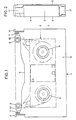
- Fig. 1 shows a container 1 for receiving a mini magnetic tape cassette 2, which is shown in dash-dotted lines in the figure shown.
- the outer dimensions of the container correspond to a standardized reversible cassette which is suitable for a video device of a specific video system.
- a small cassette for portable devices can be played in a home device that is suitable for a larger cassette with a long playing time.
- the magnetic tape of the inserted mini-cassette 2 (shown in dash-dotted lines in the figure) assumes the starting position in the container, which is required to pick up the magnetic tape from the normal position required in home appliances by means of the device's own tape transport means and to pull it out of the container or the mini-cassette.
- the container for holding the mini-cassette consists of a rectangular frame part 3 with an integrally connected base plate 4 and a pivotable cover 5.
- the frame 3 is continuously open on a long side 6, ie the magnetic tape can be led out from this side.
- the lid 5 is connected on both outer sides via a joint 7 to the short side legs of the frame.
- two tape guide elements 9, 9 ' one of which is arranged on its own swivel arm 10, 10', the magnetic tape is standardized into that of the appropriate cassette.
- the container 1 can be seen in the side view and shows the frame 3 with base plate 4 and the cover 5 extending over the frame.
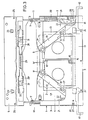
- Fig. 3 shows the container 1 in the open state when inserting the closed mini-cassette, the position of which is indicated by dash-dotted lines in its outer contours.
- the lid 5 of the opened container is completely folded back, and the mini-cassette 2 can thus be inserted without difficulty.
- the two side slides 12, 12 'must be pulled out of the container at the same time until a noticeable stop.
- the sideshift locks in the pulled-out position and remains in this position. In this process, the lid lock is released at the same time, and the lid can be opened or it is raised independently by means of a torsion spring.
- the tape guide elements 9.9 ' which are mounted on the swivel arms 10, 10' assigned to them, assume the starting position swung inwards for the insertion of the mini-cassette.
- the two swivel arms 10, 10 ' are controlled by a sliding plate 13, 13' inserted in the base plate 4 of the container.
- the two sliding plates are guided on both sides on their long sides in the floor and each have a recess in their center for receiving the cassette winding spools, the winding spools engaging in the recesses with a guide flange.
- notches and projections spanning the outer sides 14, 14 ' are provided such that a centering pin 15, 15' is to be arranged on the center line of the container on each of these.
- the centering pins are used to determine the exact position when inserting a mini-cassette into the container and simultaneously unlock the two half-cassettes.
- the side slides are each in engagement with the opposite sliding plate, so that, for. B. when pulling out the right side slider 12 according to the drawing, the left sliding plate 13 'is pushed towards the center into the starting position and vice versa.
- Both sliding plates each have a driving pin 16, 16 'which engages in a longitudinal slot 17, 17' of the swivel arm assigned to the respective sliding plate side.
- the swivel arms are each rotatably supported by a bearing pin 18 which is arranged in the frame 3 of the container.
- the rectangular frame 3 is closed with a partial cover 19.
- the partial cover 19 is shown broken on the shorter leg of the rectangular frame part 3 and thus reveals an inner part of the frame.
- the locking slide 11 with compression spring 20, which can be recognized in its entire function as a result, is immersed in the frame 3 of the housing when the container is inserted into a home appliance and actuates a locking pawl 22 via a run-up slope 21, which pawl 18 on the bearing pin 18 together with the swivel arm 10 is stored.
- the lid 5 which is shown in broken form for reasons of simple illustration, has on the inner side facing away from the pivot point of the joint 7 two symmetrically arranged latching hooks 23, 23 ', which serve to lock the lid by the side slides in the closed state of the container .
- the latching hooks 23, 23 ' engage in assigned rectangular cutouts 24, 24' of the frame 3 or the partial cover 19.
- the side slides are closed when the lid is closed by two vertically protruding pins 25, which are located in the lid on both sides near the latching hooks 25 'triggered, as soon as the pins dip into the cutouts 26, 26' assigned to the frame during the lid closing process, the detent pawls 27, 27 'blocking the side slides are hereby triggered.
- the unlocking slides 28, 28 ' have locking lugs 31, 31', each of which engages in a cutout in the half part of a mini-cassette inserted in the housing when the cover is closed, and cancels the coil lock assigned to the mini-cassette.
- the unlocking slides 28, 28 ' move with the extendable or pluggable half parts of the mini-cassette.
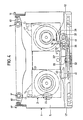
- the frame part receiving the side slider and opposite the free band exit is shown broken away, the housing being drawn in the closed state and the inserted mini cassette being indicated by dash-dotted lines.
- the two side slides 12, 12 ' have in the inner frame part of the housing area a part which is designed as a toothed rack 32, 32' and overlaps at different levels and the two toothed rack parts engage together to form a coupling gearwheel 33 which is fixedly mounted in the middle of the lower frame part stand. This ensures that both side shifters cover the same distances when actuated, or even when only one side shifter is actuated, the sliding plates 13, 13 'and swivel arms 10, 10' connected to them are always pivoted simultaneously and in the same way.
- the coupling gear 33 connecting the rack part of the side shifters has one Damping device that only works in one direction of rotation.
- the rack part of the left side slide 12 'connected to the right sliding plate 13 according to the position of the drawing carries a bearing plate 34 which is mounted on an axis of rotation 35 and is partially pivotable.
- a gear 36 is arranged on the bearing plate and can be brought into engagement with a spool flange 38 of a winding body of the inserted mini-cassette provided with saw teeth via a driving wheel 37.
- the gear 36 consists of a double gear 39 which engages with the rack part of the right side slider 12 via a gear stage and drives a further double gear with the other gear stage via an idler gear which is designed as a driving gear 37 for the spool flange 38 of the mini-cassette .
- the bearing plate 34 and thus the gear 36 is brought into engagement position by a tension spring.
- the gearbox, i.e. H. the driving wheel 37 and the toothed coil flange 38 of the mini-cassette remain engaged until the mini-cassette has almost reached its assembled starting position due to the opening process of the container.
- a siphon 40 attached to the right-hand side slide 12 or rack part strikes the bearing plate 34 of the transmission and removes the engagement of the driving wheel 37 in the spool flange 38 of the mini-cassette.
- the two side slides 12, 12 ' are connected to a tension spring 41.
- This tension spring acts as an energy accumulator, which is pulled up by pulling out the side slides and ensures that all necessary movement functions run automatically when the lid is closed.
- the housing cover of the container can only be opened after the two side slides have been pulled out. These snap into their end positions and the cover of the housing can be opened.
- the mini cassette can be placed in the container. Guide tabs on the mini-cassette ensure the correct position of the cassette in the container. When inserting the cassette, the centering pins in the housing dip into the cassette and unlock the two half parts of the cassette. At the same time, the half parts of the cassette are anchored on the sliding plates.
- the locking lugs of the unlocking slides in the lid dip into corresponding recesses in the mini-cassette and release the winding spool lock of the cassette.
- the side shifters are unlocked and the half-parts of the mini-cassette are pulled apart by means of an energy store in the housing and brought to the required center distance, which is required for the tape winding drive in the home device.
- the swivel arms with the tape guide elements simultaneously bring the magnetic tape into the position required by the standard cassette. This overall process takes place in a dampened manner by taking appropriate precautions.
- the pawls of the locking slides engage on both sides through a slot in the half parts of the cassette and prevent the magnetic tape from becoming loose.
- the container with the mini cassette can now be handled like a standard reversible cassette for the home device.
- the locking of the winding spools is released by the pawl in the container, and the magnetic tape is free.
- the gear is brought and brought into engagement with a driving wheel on a spool flange with teeth on the spool body of the mini-cassette.
- the gear is driven by engagement with a rack part of a side slider and thus winds up the excess magnetic tape that results from the pushing together of the two cassette half parts.
- the gearbox is returned to its starting position and anchored there by the siphon before the cover is opened.
- the latch of the lid lock is released, the lid can be opened and the mini-cassette can be removed.
Landscapes
- Packaging Of Annular Or Rod-Shaped Articles, Wearing Apparel, Cassettes, Or The Like (AREA)
- Coating Apparatus (AREA)
Abstract
Description
Die Erfindung betrifft einen Behälter zur Aufnahme einer Mini-Magnetbandkassette in einem für eine standardisierte Wendekassette eines bestimmten Videosystems geeigneten Videogerät, wobei die Mini-Kassette aus zwei, in Haupterstreckungsrichtung der Kassette gegeneinander verschiebbaren und in der Ausgangslage verriegelbaren Halbteilen besteht, daß ferner der Behälter zwei symmetrisch zueinander angeordnete Schwenkarme mit Bandführungselementen aufweist, die das in der Ausgangslage befindliche Magnetband der Mini-Kassette hintergreifen und innerhalb des Behälters in eine der standardisierten Kassette entsprechende Lage bringen.The invention relates to a container for holding a mini magnetic tape cassette in a video device suitable for a standardized reversible cassette of a certain video system, the mini cassette consisting of two half parts which can be displaced in the main direction of extension of the cassette and can be locked in the starting position, and that the container two has symmetrically arranged swivel arms with tape guide elements which engage behind the magnetic tape of the mini-cassette in the starting position and bring it into a position corresponding to the standardized cassette within the container.
Mit der fortschreitenden Miniaturisierung der Elektronik ist die Größe von Magnetband-Aufzeichnungs- und Wiedergabegeräten in zunehmender Weise von der Größe des Magnetbandträgers abhängig. Da als Magnetbandträger vorzugsweise Kassetten mit zwei nebeneinander angeordneten Bandwickelspulen in den modernen Geräten zur Ton- und Bildaufzeichnung eingesetzt werden, ergibt sich die naheliegende Forderung, daß auch -möglichst kleine Kassetten insbesondere bei tragbaren Geräten zu verwenden sind. Bei Heimgeräten hingegen wird vom Benutzer solcher Geräte gewünscht, daß die Kassette von ihrem Bandvolumen her eine möglichst lange Spieldauer ermöglicht. Aus den unterschiedlichen Anforderungen an ein Heim-Videogerät einerseits und an ein tragbares Video-Aufzeichnungsgerät, insbesondere an ein in eine Video-Kamera integriertes Kassettengerät andererseits, ergibt sich eine nur durch einen Kompromiß zu lösende Aufgabe in der Verwendung von zwei unterschiedlichen Kassetten, nämlich einer möglichst kleinen und leichten Kassette für ein tragbares Gerät und einer anderen Kassette mit großer Spieldauer für das Heimgerät. Es ist naheliegend, daß somit sogleich der Wunsch gegeben ist, die kleine Kassette mit der zwangsläufig geringeren Spieldauer auch im Heimgerät abspielen zu können.With the increasing miniaturization of electronics, the size of magnetic tape recording and reproducing devices is increasingly dependent on the size of the magnetic tape carrier. Since cassettes with two tape reels arranged next to one another are preferably used as magnetic tape carriers in modern devices for sound and image recording, the obvious requirement arises that cassettes which are as small as possible are to be used in particular in portable devices. In the case of home devices, on the other hand, the user of such devices desires that the tape volume enables the longest possible playing time. The different requirements for a home video device on the one hand and for a portable video recording device, in particular for a cassette device integrated in a video camera on the other hand, result in a problem that can only be solved by a compromise in the use of two different cassettes, namely one as small and light as possible cassette for a portable device and another cassette with a long playing time for the home device. It is obvious that there is immediately a desire to be able to play the small cassette with the inevitably shorter playing time in the home device.
Hierfür wurden bereits Ausgleichsstücke vorgeschlagen, die das Einsetzen der kleineren Kassette in ein Heimgerät ermöglichen. Solche Konstruktionen sind jedoch sehr kompliziert, da eine aufwendige Technik zum Antrieb der Wickelspulen mit unterschiedlichen Achsabständen erforderlich ist. Der unterschiedliche Achsabstand ist zwangsläufig durch die unterschiedliche Kassettengröße gegeben. Eine erhebliche Vereinfachung der Anpassung einer Kleinkassette an die Größe einer Standardkassette für ein Heimgerät gleichen Systems ergibt sich bei Verwendung einer Mini-Kassette der eingangs genannten Art, wie sie nach der europäischen Patentanmeldung EP-A-77 876 (zu benicksichtigen nach Art 54 (3)) vorgeschlagen wird. Nach diesem Vorschlag werden die Band-Wickelkörper mit umschließendem Kassetten-Gehäuseteil in Längsrichtung auseinandergezogen, und die Wickelkörperlage der kleineren Kassette kann sich dem veränderten Achsabstand für den Wickelkörperantrieb des Heimgeräts anpassen.Compensation pieces have already been proposed for this purpose, which enable the smaller cassette to be inserted into a home appliance. However, such constructions are very complicated because a complex technology for driving the winding coils with different center distances is required. The different center distance is inevitably given by the different cassette size. A considerable simplification of the adaptation of a small cassette to the size of a standard cassette for a home appliance of the same system results when using a mini-cassette of the type mentioned at the outset, as described in European patent application EP-A - 77 876 (to be considered in accordance with Art 54 (3 )) is proposed. According to this proposal, the tape winding bodies with the surrounding cassette housing part are pulled apart in the longitudinal direction, and the winding core position of the smaller cassette can adapt to the changed center distance for the winding body drive of the home device.
Aufgabe der Erfindung ist es, einen Behälter zur Aufnahme einer ausziehbaren Mini-Kassette obig geschilderter Ausführung zu schaffen, der alle erforderlichen Funktionen erfüllt, um eine Mini-Kassette in einfachster Weise in einem Heimgerät einsetzen zu können, das nach einem für standardisierte Wende-Kassetten geeigneten Videosystem arbeitet.The object of the invention is to provide a container for receiving a pull-out mini-cassette of the above-described embodiment, which fulfills all the functions required to be able to use a mini-cassette in a home device in a very simple manner, according to one for standardized reversible cassettes suitable video system works.
Die Lösung dieser Aufgabe erfolgt erfindungsgemäß durch die im Anspruchs 1 angegebenen Maßnahmen. Vorteilhafte Weiterbildungen ergeben sich aus den abhängigen Ansprüchen 2-12.This object is achieved according to the invention by the measures specified in
Die Erfindung wird nachfolgend unter Bezugnahme auf die Zeichnungsfiguren beispielsweise erläutert. Es zeigen :
Figur 1 einen Behälter im geschlossenen Zustand,Figur 2 eine Seitenansicht der Fig. 1,Figur 3 eine Draufsicht des Behälters in geöffnetem Zustand,Figur 4 eine Draufsicht ähnlich der Fig. 1, jedoch mit teilweise aufgebrochen gezeichnetem Behälterrahmen.
- 1 shows a container in the closed state,
- FIG. 2 shows a side view of FIG. 1,
- FIG. 3 shows a top view of the container in the open state,
- Figure 4 is a plan view similar to Fig. 1, but with a partially broken container frame.
Die Fig. 1 zeigt einen Behälter 1 zur Aufnahme einer MiniMagnetbandkassette 2, die in der dargestellten Figur strichpunktiert eingezeichnet ist. Der Behälter entspricht in seinen äußeren Abmessungen einer standardisierten Wendekassette, die für ein Videogerät eines bestimmten Videosystems geeignet ist. Somit kann eine kleine Kassette für tragbare Geräte in einem Heimgerät, das für eine größere Kassette mit langer Spieldauer geeignet ist, abgespielt werden. Das Magnetband der eingelegten MiniKassette 2 (strichpunktiert in der Figur eingezeichnet) nimmt im Behälter die Ausgangslage ein, die erforderlich ist, um das Magnetband aus der in Heimgeräten erforderlichen Normallage durch geräteeigene Bandtransportmittel aufzunehmen und aus dem Behälter bzw. der Mini-Kassette herauszuziehen. Der Behälter zur Aufnahme der MiniKassette besteht aus einem rechteckigen Rahmenteil 3 mit einer einstückig verbundenen Bodenplatte 4 und einem schwenkbaren Deckel 5. Der Rahmen 3 ist an einer Längsseite 6 durchgehend geöffnet, d. h. aus dieser Seite kann das Magnetband herausgeführt werden. Der Deckel 5 ist an beiden äußeren Seiten über jeweils ein Gelenk 7 mit den kurzen Seitenschenkeln des Rahmens verbunden. In der Bodenplatte 4 und im Deckel 5 des Gehäuses sind deckungsgleich kreisrunde oder elliptische Aussparungen 8 vorhanden, die der Zugänglichkeit und Aufnahme der Wickelspulen einer in den Behälter eingelegten Mini-Kassette dienen. Durch zwei Bandführungselemente 9, 9', von denen je eines auf einem eigenen Schwenkarm 10, 10' angeordnet ist, wird das Magnetband in die der standardisierten Kassette entsprechenden Lagegebracht.Fig. 1 shows a
Aus der Fig. 2 ist der Behälter 1 in der Seitenansicht erkennbar und zeigt den Rahmen 3 mit Bodenplatte 4 und den über den Rahmen greifenden Deckel 5. Seitlich des Rahmens und an der geöffneten Längsseite 6 des Behälters befindet sich auf jeder Seite ein Sperrschieber 11, 11' und an der gegenüberliegenden geschlossenen Längsseite des Rahmens an beiden Außenseiten ein in Längsrichtung herausziehbarer Seitenschieber 12, 12'.2, the
Die Fig. 3 zeigt den Behälter 1 in geöffnetem Zustand beim Einlegen der geschlossenen Mini- Kassette, deren Lage in ihren Außenkonturen strichpunktiert angedeutet ist. Der Deckel 5 des geöffneten Behälters ist hierbei vollständig zurückgeklappt, und die Mini-Kassette 2 kann somit ohne Schwierigkeiten eingelegt werden. Um jedoch den vorher geschlossenen Behälter 1 zu öffnen, sind die beiden Seitenschieber 12, 12' gleichzeitig aus dem Behälter bis zu einem spürbaren Anschlag herauszuziehen. Die Seitenschieber rasten in der herausgezogenen Lage ein und verbleiben in dieser Stellung. Bei diesem Vorgang wird gleichzeitig die Deckelverriegelung aufgehoben, und der Deckel läßt sich aufklappen oder er wird selbständig mittels einer Drehfeder angehoben. Weiterhin nehmen beim Öffnen des Behälters die Bandführungselemente 9.9', die auf den ihnen zugeordneten Schwenkarmen 10, 10' gelagert sind, die nach innen eingeschwenkte für das Einlegen der Mini-Kassette erforderliche Ausgangslage ein. Die Steuerung der beiden Schwenkarme 10, 10' wird durch je eine in der Bodenplatte 4 des Behälters eingesetzte Schiebeplatte 13, 13' vorgenommen. Die beiden Schiebeplatten sind beidseitig an ihren Längsseiten im Boden geführt und weisen etwa in ihrer Mitte je eine Aussparung für die Aufnahme der Kassetten- Wickelspulen auf, wobei die Wickelspulen mit einem Führungsflansch in die Aussparungen eingreifen. Unmittelbar bei der inneren Stoßstelle der beiden Schiebeplatten sind an den Außenseiten 14, 14' übergreifende Ausklinkungen und Vorsprünge derart vorhanden, daß auf diesen je ein Zentrierstift 15, 15' auf der Mittellinie des Behälters anzuordnen ist. Die Zentrierstifte dienen der exakten Lagebestimmung beim Einlegen einer Mini-Kassette in den Behälter und entriegeln hierbei gleichzeitig die beiden Kassetten-Halbteile. Die Seitenschieber sind jeweils mit der gegenüberliegenden Schiebeplatte in Eingriff, so daß z. B. beim Herausziehen des nach Zeichnung rechten Seitenschiebers 12 die linke Schiebeplatte 13' zur Mitte in die Ausgangslage geschoben wird und umgekehrt. Beide Schiebeplatten weisen je einen Mitnahmezapfen 16, 16' auf, der in einen Längsschlitz 17, 17' des der jeweiligen Schiebeplattenseite zugeordneten Schwenkarm greift. Die Schwenkarme sind über je einen Lagerzapfen 18, der im Rahmen 3 des Behälters angeordnet ist, drehbar gelagert. Der rechteckige Rahmen 3 ist mit einer Teil-Abdeckung 19 verschlossen. Auf der rechten Seite der dargestellten Figur ist am kürzeren Schenkel des rechteckigen Rahmenteils 3 die Teilabdeckung 19 aufgebrochen gezeichnet und läßt somit einen inneren Teil des Rahmens erkennen. Der hierdurch in seiner gesamten Funktion erkennbare und beidseitig angeordnete Sperrschieber 11 mit Druckfeder 20 taucht beim Einsetzen des Behälters in ein Heimgerät in den Rahmen 3 des Gehäuses ein und betätigt über eine Anlaufschräge 21 eine Sperrklinke 22, die auf dem Lagerzapfen 18 zusammen mit dem Schwenkarm 10 gelagert ist. Hierbei wird die Sperrklinke 22 aus dem Eingriff der Wickelspulen einer im Behälter befindlichen Mini-Kassette genommen, und die Wickelspule ist für den Antrieb freigegeben. Der Deckel 5, der aus Gründen einfacher Darstellung in abgebrochener Form gezeichnet ist, weist auf der vom Drehpunkt des Gelenks 7 abgewandten inneren Seite zwei symmetrisch angeordnete Rasthaken 23, 23' auf, die zur Verriegelung des Deckels durch die Seitenschieber im geschlossenen Zustand des Behälters dienen. Die Rasthaken 23, 23' greifen zu diesem Zweck in zugeordnete rechteckige Ausschnitte 24, 24' des Rahmens 3 bzw. der Teilabdeckung 19. Die Seitenschieber werden beim Schließen des Deckels durch zwei in der Nähe der Rasthaken beidseitig im Deckel angebrachte senkrecht abstehende Stifte 25, 25' ausgelöst, sobald die Stifte beim Deckelschließvorgang in die dem Rahmen zugeordnete Ausbrüche 26, 26' eintauchen, werden hierdurch die die Seitenschieber sperrenden Rastklinken 27, 27' ausgelöst. Weiterhin befinden sich im Inneren des Deckels zwei Entriegelungsschieber 28 und 28', die über eine Zugfeder 29 gekoppelt und in Längsführungen 30 gelagert sind. Die Entriegelungsschieber 28, 28' weisen Riegelnasen 31, 31' auf, die jeweils beim Schließen des Deckels in je einen Ausschnitt im Halbteil einer im Gehäuse eingelegten MiniKassette eingreifen und die der Mini-Kassette zugeordnete eigene Spulenverriegelung aufheben. Die Entriegelungsschieber 28, 28' bewegen sich mit den ausziehbaren oder zusammensteckbaren Halbteilen der Mini- Kassette mit.Fig. 3 shows the
Aus der Fig. 4 ist der die Seitenschieber aufnehmende, dem freien Bandaustritt gegenüberliegende Rahmenteil aufgebrochen dargestellt, wobei das Gehäuse im geschlossenen Zustand gezeichnet, und die eingelegte Mini Kassette strichpunktiert angedeutet ist. Die beiden Seitenschieber 12, 12' weisen im inneren Rahmenteil des Gehäusebereichs ein als Zahnstange 32, 32' ausgebildeten Teil auf, der sich auf unterschiedlicher Ebene überschneidet und die beiden Zahnstangenteile gemeinsam in Eingriff zu einem etwa in der Mitte des unteren Rahmenteils fest gelagerten Koppelzahnrad 33 stehen. Hierdurch wird erreicht, daß beide Seitenschieber bei Betätigung gleichzeitig gleiche Wegstrecken zurücklegen bzw. auch bei Betätigung von nur einem Seitenschieber die mit diesen verbundenen Schiebeplatten 13, 13' und Schwenkarme 10. 10' immer gleichzeitig und in gleicher Weise verschwenkt werden. Das den Zahnstangenteil der Seitenschieber verbindende Koppelzahnrad 33 weist eine Dämpfungseinrichtung auf, die nur in einer Drehrichtung wirkt. Das nach Lage der Zeichnung mit der rechten Schiebeplatte 13 verbundene Zahnstangenteil des linken Seitenschiebers 12' trägt eine Lagerplatte 34, die auf einer Drehachse 35 gelagert und teilweise schwenkbar ist. Auf der Lagerplatte ist ein Getriebe 36 angeordnet, das über ein Mitnahmerad 37 in Eingriff zu einem mit einer Sägeverzahnung versehenem Spulenflansch 38 eines Wickelkörpers der eingelegten Mini-Kassette bringbar ist.4, the frame part receiving the side slider and opposite the free band exit is shown broken away, the housing being drawn in the closed state and the inserted mini cassette being indicated by dash-dotted lines. The two
Das Getriebe 36 besteht aus einem Doppelzahnrad 39, das über eine Zahnradstufe mit dem Zahnstangenteil des rechten Seitenschiebers 12 in Eingriff ist und mit der anderen Zahnradstufe über ein Zwischenrad ein weiteres Doppelzahnrad antreibt, das als Mitnahmerad 37 für den Spulenflansch 38 der Mini-Kassette ausgebildet ist. Die Lagerplatte 34 und somit das Getriebe 36 wird durch eine Zugfeder in Eingriffsstellung gebracht. Das Getriebe, d. h. das Mitnahmerad 37 und der verzahnte Spulenflansch 38 der Mini- Kassette bleibt solange in Eingriff, bis durch den Öffnungsvorgang des Behälters die Mini-Kassette nahezu ihre zusammengefügte Ausgangslage erreicht hat. Kurz vor dem Verriegeln der beiden Kassetten-Halbteile der Mini-Kassette stößt ein auf dem rechten Seitenschieber 12 bzw. Zahnstangenteil angebrachter Abheber 40 auf die Lagerplatte 34 des Getriebes und hebt den Eingriff des Mitnahmerades 37 in den Spulenflansch 38 der Mini-Kassette auf. Die beiden Seitenschieber 12, 12' sind mit einer Zugfeder 41 verbunden. Diese Zugfeder wirkt als Kraftspeicher, der durch das Herausziehen der Seitenschieber aufgezogen wird und Sorge trägt, daß beim Schließen des Deckels alle erforderlichen Bewegungsfunktionen automatisch ablaufen.The
In einer kurzen Zusammenfassung werden die einzelnen Handhabungen und Funktionsabläufe nochmals erläutert. Der Gehäusedeckel des Behälters läßt sich erst öffnen, nachdem die beiden Seitenschieber herausgezogen sind. Diese rasten in ihren Endstellungen ein, und der Deckel des Gehäuses kann geöffnet werden. Die Mini- Kassette kann in den Behälter eingelegt werden. Führungsnasen an der Mini-Kassette sorgen für die richtige Lage der Kassette im Behälter. Beim Einlegen der Kassette tauchen die im Gehäuse befindlichen Zentrierstifte in die Kassette ein und entriegeln die beiden Halbteile der Kassette. Hierbei werden gleichzeitig die Halbteile der Kassette auf den Schiebeplatten verankert.The individual operations and functional sequences are explained again in a short summary. The housing cover of the container can only be opened after the two side slides have been pulled out. These snap into their end positions and the cover of the housing can be opened. The mini cassette can be placed in the container. Guide tabs on the mini-cassette ensure the correct position of the cassette in the container. When inserting the cassette, the centering pins in the housing dip into the cassette and unlock the two half parts of the cassette. At the same time, the half parts of the cassette are anchored on the sliding plates.
Wird nun der Deckel des Behälters geschlossen, tauchen die Riegelnasen der Entriegelungsschieber im Deckel in entsprechende Ausnehmungen in die Mini-Kassette ein und lösen die Wickelspulenverriegelung der Kassette. Gleichzeitig werden die Seitenschieber entriegelt und mittels Kraftspeicher im Gehäuse die Halbteile der Mini-Kassette auseinandergezogen und auf den erforderlichen Achsabstand, der für den Bandwickelantrieb im Heimgerät erforderlich ist, gebracht. Die Schwenkarme mit den Bandführungselementen bringen das Magnetband gleichzeitig in die nach der Standardkassette erforderliche Lage. Dieser Gesamtvorgang läuft durch entsprechende Vorkehrung gedämpft ab. In der auseinandergezogenen Endstellung der Kassetten-Halbteile und des Magnetbandes greifen auf beiden Seiten durch einen Schlitz in den Halbteilen der Kassette die Sperrklinken der Sperrschieber und verhindern das Lockerwerden des Magnetbandes. Der Behälter mit der Mini- Kassette kann nun wie eine Standard-Wendekassette für das Heimgerät gehandhabt werden. Beim Einführen des Behälters in das Heimgerät wird die Verriegelung der Wickelspulen durch die im Behälter befindliche Sperrklinke aufgehoben, und das Magnetband ist frei.If the lid of the container is now closed, the locking lugs of the unlocking slides in the lid dip into corresponding recesses in the mini-cassette and release the winding spool lock of the cassette. At the same time, the side shifters are unlocked and the half-parts of the mini-cassette are pulled apart by means of an energy store in the housing and brought to the required center distance, which is required for the tape winding drive in the home device. The swivel arms with the tape guide elements simultaneously bring the magnetic tape into the position required by the standard cassette. This overall process takes place in a dampened manner by taking appropriate precautions. In the pulled-apart end position of the cassette half parts and the magnetic tape, the pawls of the locking slides engage on both sides through a slot in the half parts of the cassette and prevent the magnetic tape from becoming loose. The container with the mini cassette can now be handled like a standard reversible cassette for the home device. When the container is inserted into the home device, the locking of the winding spools is released by the pawl in the container, and the magnetic tape is free.
Soll die Mini-Kassette wieder aus dem Behälter genommen werden, so sind die Seitenschieber herauszuziehen. Bei diesem Vorgang wird zusätzlich zu den übrigen nur umkehrbaren Funktionsabläufen das Getriebe mit einem Mitnahmerad an einen Spulenflansch mit Verzahnung des Spulenkörpers der Mini-Kassette herangeführt und in Eingriff gebracht. Während des Vorgangs des Auseinanderziehens der Seitenschieber wird das Getriebe durch Eingriff in ein Zahnstangenteil eines Seitenschiebers angetrieben und spult somit das überschüssige Magnetband, das sich durch das Zusammenschieben der beiden KassettenHalbteile ergibt, auf. Durch den Abheber wird vor Öffnen des Deckels das Getriebe wieder in seine Ausgangslage zurückgeführt und dort verankert. Gleichzeitig wird die Rastklinke der Deckelverriegelung aufgehoben, der Deckel kann geöffnet und die Mini-Kassette entnommen werden.If the mini-cassette is to be taken out of the container again, the side slides have to be pulled out. In this process, in addition to the other only reversible functional sequences, the gear is brought and brought into engagement with a driving wheel on a spool flange with teeth on the spool body of the mini-cassette. During the process of pulling apart the side slides, the gear is driven by engagement with a rack part of a side slider and thus winds up the excess magnetic tape that results from the pushing together of the two cassette half parts. The gearbox is returned to its starting position and anchored there by the siphon before the cover is opened. At the same time, the latch of the lid lock is released, the lid can be opened and the mini-cassette can be removed.
Claims (12)
Priority Applications (1)
| Application Number | Priority Date | Filing Date | Title |
|---|---|---|---|
| AT83103656T ATE29081T1 (en) | 1982-06-09 | 1983-04-15 | CASE FOR HOLDING A MAGNETIC TAPE CASSETTE. |
Applications Claiming Priority (2)
| Application Number | Priority Date | Filing Date | Title |
|---|---|---|---|
| DE3221761 | 1982-06-09 | ||
| DE19823221761 DE3221761A1 (en) | 1982-06-09 | 1982-06-09 | CONTAINER TO RECEIVE A MAGNETIC TAPE CASSETTE |
Publications (2)
| Publication Number | Publication Date |
|---|---|
| EP0100397A1 EP0100397A1 (en) | 1984-02-15 |
| EP0100397B1 true EP0100397B1 (en) | 1987-08-19 |
Family
ID=6165714
Family Applications (1)
| Application Number | Title | Priority Date | Filing Date |
|---|---|---|---|
| EP83103656A Expired EP0100397B1 (en) | 1982-06-09 | 1983-04-15 | Adapter for a magnetic tape cassette |
Country Status (5)
| Country | Link |
|---|---|
| US (1) | US4492351A (en) |
| EP (1) | EP0100397B1 (en) |
| JP (1) | JPS592271A (en) |
| AT (1) | ATE29081T1 (en) |
| DE (2) | DE3221761A1 (en) |
Families Citing this family (6)
| Publication number | Priority date | Publication date | Assignee | Title |
|---|---|---|---|---|
| EP0153137B1 (en) * | 1984-02-16 | 1990-11-28 | Matsushita Electric Industrial Co., Ltd. | Tape cassette for short-time recording |
| JPH0640413B2 (en) * | 1985-09-23 | 1994-05-25 | ソニー株式会社 | Disc opening / closing mechanism of disk cartridge |
| US5021903A (en) * | 1988-06-24 | 1991-06-04 | Rank Video Services America | Magnetic tape cartridge |
| US4964003A (en) * | 1988-06-24 | 1990-10-16 | Rank Video Services America | Tape interconnection system |
| US4920436A (en) * | 1988-06-24 | 1990-04-24 | Rank Video Services America | Magnetic tape cassette system |
| US6305631B1 (en) | 1999-09-28 | 2001-10-23 | Imation Corp. | Tape cartridge with remove to operate tape and hubs |
Citations (1)
| Publication number | Priority date | Publication date | Assignee | Title |
|---|---|---|---|---|
| EP0077876A1 (en) * | 1981-10-27 | 1983-05-04 | GRUNDIG E.M.V. Elektro-Mechanische Versuchsanstalt Max Grundig holländ. Stiftung & Co. KG. | Minicassette |
Family Cites Families (10)
| Publication number | Priority date | Publication date | Assignee | Title |
|---|---|---|---|---|
| US3701495A (en) * | 1970-08-10 | 1972-10-31 | Xerox Corp | Expandable cassette |
| US3955779A (en) * | 1974-05-28 | 1976-05-11 | Bell & Howell Company | Cartridge with removable take-up sub-cartridge |
| DE2518762A1 (en) * | 1975-04-26 | 1976-11-04 | Agfa Gevaert Ag | MULTI-PIECE FILM CASSETTE |
| JPS5291407A (en) * | 1976-01-27 | 1977-08-01 | Sony Corp | Cassette mounting device for recorder/reproducer units |
| JPS586218B2 (en) * | 1975-12-23 | 1983-02-03 | オリンパス光学工業株式会社 | tape cassette |
| US4092686A (en) * | 1976-02-17 | 1978-05-30 | Odetics, Inc. | Tape withdrawal and tensioning mechanism for video cassette recorder/reproducer |
| JPS5855577B2 (en) * | 1976-08-16 | 1983-12-10 | 松下電器産業株式会社 | magnetic tape device |
| DE2713470A1 (en) * | 1977-03-26 | 1978-09-28 | Bosch Gmbh Robert | Cassette and open spool tape recorder - has sprung mechanism for selective tensioning along tape length between spools |
| JPS595978B2 (en) * | 1978-09-22 | 1984-02-08 | 松下電器産業株式会社 | magnetic tape storage |
| JPS57123573A (en) * | 1981-01-20 | 1982-08-02 | Victor Co Of Japan Ltd | Adapter for tape cassette |
-
1982
- 1982-06-09 DE DE19823221761 patent/DE3221761A1/en not_active Withdrawn
-
1983
- 1983-04-15 EP EP83103656A patent/EP0100397B1/en not_active Expired
- 1983-04-15 DE DE8383103656T patent/DE3373157D1/en not_active Expired
- 1983-04-15 AT AT83103656T patent/ATE29081T1/en not_active IP Right Cessation
- 1983-06-09 JP JP58101853A patent/JPS592271A/en active Pending
- 1983-06-09 US US06/502,467 patent/US4492351A/en not_active Expired - Fee Related
Patent Citations (1)
| Publication number | Priority date | Publication date | Assignee | Title |
|---|---|---|---|---|
| EP0077876A1 (en) * | 1981-10-27 | 1983-05-04 | GRUNDIG E.M.V. Elektro-Mechanische Versuchsanstalt Max Grundig holländ. Stiftung & Co. KG. | Minicassette |
Also Published As
| Publication number | Publication date |
|---|---|
| ATE29081T1 (en) | 1987-09-15 |
| US4492351A (en) | 1985-01-08 |
| DE3373157D1 (en) | 1987-09-24 |
| DE3221761A1 (en) | 1983-12-15 |
| JPS592271A (en) | 1984-01-07 |
| EP0100397A1 (en) | 1984-02-15 |
Similar Documents
| Publication | Publication Date | Title |
|---|---|---|
| DE3201598C2 (en) | ||
| DE3244797C2 (en) | ||
| DE4231574C2 (en) | Tape cassette loading device | |
| DE4445834A1 (en) | Magnetic video recorder and player with video game pack player | |
| DE3146594C2 (en) | Small video cassette and associated adapter | |
| EP0100397B1 (en) | Adapter for a magnetic tape cassette | |
| DE69124405T2 (en) | Cassette loading device | |
| EP0234660B1 (en) | Recording and/or reproducing apparatus | |
| DE3327599C2 (en) | Adapter for a miniature tape cassette | |
| EP0077876B1 (en) | Minicassette | |
| DE2536274A1 (en) | LOADING / UNLOADING DEVICE FOR A MAGNETIC TAPE DRIVE ACCORDING TO THE CONTACT WRAPPING PRINCIPLE | |
| DE69016497T2 (en) | Tape cassette loaded from above for video cassette. | |
| DE69024575T2 (en) | Cassette container for tape player | |
| EP0322056B1 (en) | Recording and/or reproducing apparatus for a tape-like record carrier | |
| DE69116589T2 (en) | Tape cartridges | |
| DE69016233T2 (en) | Loading mechanism for a recording / reproducing device. | |
| DE3924107C2 (en) | ||
| EP0463320B1 (en) | Holder for magnetic tape cassettes | |
| EP0610270B1 (en) | Cassette loading device | |
| AT379465B (en) | TAPE CASSETTE | |
| DE3239892A1 (en) | VIDEO TURNTABLE | |
| DE69122443T2 (en) | Tape cassette | |
| DE2023390A1 (en) | Device for removing a tape | |
| DE2103659C2 (en) | Small cassette dictation machine | |
| DE19634475C2 (en) | Device for securing the image position with multiple exposure |
Legal Events
| Date | Code | Title | Description |
|---|---|---|---|
| PUAI | Public reference made under article 153(3) epc to a published international application that has entered the european phase |
Free format text: ORIGINAL CODE: 0009012 |
|
| AK | Designated contracting states |
Designated state(s): AT BE CH DE FR GB IT LI |
|
| 17P | Request for examination filed |
Effective date: 19840816 |
|
| RAP1 | Party data changed (applicant data changed or rights of an application transferred) |
Owner name: GRUNDIG E.M.V. ELEKTRO-MECHANISCHE VERSUCHSANSTALT |
|
| 17Q | First examination report despatched |
Effective date: 19860303 |
|
| GRAA | (expected) grant |
Free format text: ORIGINAL CODE: 0009210 |
|
| AK | Designated contracting states |
Kind code of ref document: B1 Designated state(s): AT BE CH DE FR LI |
|
| REF | Corresponds to: |
Ref document number: 29081 Country of ref document: AT Date of ref document: 19870915 Kind code of ref document: T |
|
| RBV | Designated contracting states (corrected) |
Designated state(s): AT BE CH DE FR GB IT LI |
|
| REF | Corresponds to: |
Ref document number: 3373157 Country of ref document: DE Date of ref document: 19870924 |
|
| ET | Fr: translation filed | ||
| ITF | It: translation for a ep patent filed | ||
| PLBE | No opposition filed within time limit |
Free format text: ORIGINAL CODE: 0009261 |
|
| STAA | Information on the status of an ep patent application or granted ep patent |
Free format text: STATUS: NO OPPOSITION FILED WITHIN TIME LIMIT |
|
| 26N | No opposition filed | ||
| PGFP | Annual fee paid to national office [announced via postgrant information from national office to epo] |
Ref country code: BE Payment date: 19890213 Year of fee payment: 7 |
|
| PGFP | Annual fee paid to national office [announced via postgrant information from national office to epo] |
Ref country code: CH Payment date: 19890407 Year of fee payment: 7 |
|
| PGFP | Annual fee paid to national office [announced via postgrant information from national office to epo] |
Ref country code: FR Payment date: 19890428 Year of fee payment: 7 Ref country code: AT Payment date: 19890428 Year of fee payment: 7 |
|
| ITTA | It: last paid annual fee | ||
| PGFP | Annual fee paid to national office [announced via postgrant information from national office to epo] |
Ref country code: DE Payment date: 19890505 Year of fee payment: 7 |
|
| PGFP | Annual fee paid to national office [announced via postgrant information from national office to epo] |
Ref country code: GB Payment date: 19900404 Year of fee payment: 8 |
|
| PG25 | Lapsed in a contracting state [announced via postgrant information from national office to epo] |
Ref country code: AT Effective date: 19900415 |
|
| PG25 | Lapsed in a contracting state [announced via postgrant information from national office to epo] |
Ref country code: LI Effective date: 19900430 Ref country code: CH Effective date: 19900430 Ref country code: BE Effective date: 19900430 |
|
| BERE | Be: lapsed |
Owner name: GRUNDIG E.M.V. ELEKTRO-MECHANISCHE VERSUCH SANSTL Effective date: 19900430 |
|
| PG25 | Lapsed in a contracting state [announced via postgrant information from national office to epo] |
Ref country code: FR Effective date: 19901228 |
|
| REG | Reference to a national code |
Ref country code: CH Ref legal event code: PL |
|
| PG25 | Lapsed in a contracting state [announced via postgrant information from national office to epo] |
Ref country code: DE Effective date: 19910101 |
|
| REG | Reference to a national code |
Ref country code: FR Ref legal event code: ST |
|
| PG25 | Lapsed in a contracting state [announced via postgrant information from national office to epo] |
Ref country code: GB Effective date: 19910415 |
|
| GBPC | Gb: european patent ceased through non-payment of renewal fee |