EP0322056B1 - Recording and/or reproducing apparatus for a tape-like record carrier - Google Patents
Recording and/or reproducing apparatus for a tape-like record carrier Download PDFInfo
- Publication number
- EP0322056B1 EP0322056B1 EP88202930A EP88202930A EP0322056B1 EP 0322056 B1 EP0322056 B1 EP 0322056B1 EP 88202930 A EP88202930 A EP 88202930A EP 88202930 A EP88202930 A EP 88202930A EP 0322056 B1 EP0322056 B1 EP 0322056B1
- Authority
- EP
- European Patent Office
- Prior art keywords
- cassette
- cassette holder
- support
- holder
- pressure device
- Prior art date
- Legal status (The legal status is an assumption and is not a legal conclusion. Google has not performed a legal analysis and makes no representation as to the accuracy of the status listed.)
- Expired - Lifetime
Links
- 238000003780 insertion Methods 0.000 claims description 25
- 230000037431 insertion Effects 0.000 claims description 25
- 230000008878 coupling Effects 0.000 claims description 7
- 238000010168 coupling process Methods 0.000 claims description 7
- 238000005859 coupling reaction Methods 0.000 claims description 7
- 238000004804 winding Methods 0.000 description 20
- 230000009471 action Effects 0.000 description 10
- 238000006243 chemical reaction Methods 0.000 description 3
- 238000006073 displacement reaction Methods 0.000 description 3
- 230000000694 effects Effects 0.000 description 2
- 238000000034 method Methods 0.000 description 2
- 230000008569 process Effects 0.000 description 2
- 238000007789 sealing Methods 0.000 description 2
- 208000036829 Device dislocation Diseases 0.000 description 1
- 239000000969 carrier Substances 0.000 description 1
- 238000007654 immersion Methods 0.000 description 1
- 230000003993 interaction Effects 0.000 description 1
- 230000007246 mechanism Effects 0.000 description 1
- 230000004044 response Effects 0.000 description 1
- 230000005236 sound signal Effects 0.000 description 1
- 230000007704 transition Effects 0.000 description 1
Images


Classifications
-
- G—PHYSICS
- G11—INFORMATION STORAGE
- G11B—INFORMATION STORAGE BASED ON RELATIVE MOVEMENT BETWEEN RECORD CARRIER AND TRANSDUCER
- G11B15/00—Driving, starting or stopping record carriers of filamentary or web form; Driving both such record carriers and heads; Guiding such record carriers or containers therefor; Control thereof; Control of operating function
- G11B15/60—Guiding record carrier
- G11B15/66—Threading; Loading; Automatic self-loading
-
- G—PHYSICS
- G11—INFORMATION STORAGE
- G11B—INFORMATION STORAGE BASED ON RELATIVE MOVEMENT BETWEEN RECORD CARRIER AND TRANSDUCER
- G11B15/00—Driving, starting or stopping record carriers of filamentary or web form; Driving both such record carriers and heads; Guiding such record carriers or containers therefor; Control thereof; Control of operating function
- G11B15/675—Guiding containers, e.g. loading, ejecting cassettes
- G11B15/67581—Guiding containers, e.g. loading, ejecting cassettes with pivoting movement of the cassette holder
- G11B15/67584—Guiding containers, e.g. loading, ejecting cassettes with pivoting movement of the cassette holder outside the apparatus
Definitions
- the invention relates to a recording and / or reproducing device for a tape-shaped recording medium, which is accommodated in a cassette that can be inserted into the device with two adjacent, rotatably drivable winding cores for the same, with rotatably drivable through at least a first main wall of the cassette the winding cores in drive connection bringable mandrels for driving the winding cores and with a pivotable about a pivot axis, essentially shaft-shaped cassette holder, which is between a loading position in which a cassette with a first side wall in the direction of the shaft into the cassette holder into at least one the limit stop provided in the cassette receptacle can be inserted, and an operating position can be pivoted in which a cassette inserted into the cassette receptacle assumes an operating position in which the winding mandrels m with the winding cores in drive connection, as well as with at least one pressure device under the action of a spring, which, when the cassette holder is in its loading position
- Such a device is known from AT-PS 298.104.
- the pressure device is arranged in a fixed manner within the device, and when a cassette inserted into the cassette holder is pivoted into its operating position, it is only immediately before the cassette reaches its operating position reached, in active connection with it.
- a cassette is not correctly inserted into the cassette holder by the user into the insertion position defined here by two limit stops on the cassette holder, which can occur, for example, if the cassette is jammed under unfavorable frictional conditions, it can occur when the cassette which is not correctly inserted is pivoted in their operating position to disturbances when immersing the mandrels intended to drive the two winding cores into the cassette, because this immersion of the two mandrels occurs at a time when the pressure device does not yet cooperate with the cassette and therefore does not yet insert the cassette into hers Insertion position in the cassette holder is pressed and held in the same.
- the stationary pressure device abruptly interacts with a cassette inserted into the cassette holder, which can be perceived as disruptive by the user when manually adjusting the cassette holder, since resistance is suddenly felt in the sequence of movements, and what also leads to one increased wear of both the pressure device and the cassette can result.
- the object of the invention is to avoid the difficulties mentioned above and to provide a device in which a cassette inserted into the cassette holder is pressed into its insertion position in the cassette holder at a relatively early point in time when the cassette holder is pivoted into its operating position and is held in the same and in which an abrupt attack of the pressure device on the cassette is avoided.
- the invention is characterized in that the pressure device on a pivot axis between a starting position and a working position pivotable carrier is arranged, that the carrier is coupled to the cassette holder for at least partially jointly pivoting the two via at least one coupling device and that the pivot axis of the carrier is arranged offset parallel to the pivot axis of the cassette holder, the distance between the at the contact point provided on the pressure device from the pivot axis of the cassette holder is larger on the one hand when the cassette holder is in its loading position and the carrier in its starting position and on the other hand is smaller than the distance when the cassette holder is in its operating position without a cassette inserted into it and the carrier in its working position the corresponding point of attack located on a cassette inserted in the cassette holder from the pivot axis of the cassette holder and when conspiring lower the carrier from its starting position into its working position, the point of attack provided on the pressing device moves towards the corresponding point of attack located on a cassette inserted into the cassette holder and thereby comes to attack the same.
- the arrangement of the pressure device on the pivotable carrier and the offset of the pivot axes of the cassette holder and the carrier results in a relative movement between the pressure device attached to the carrier and a cassette inserted into the cassette holder when the two are pivoted into their operating or working position reached, according to which the pressure device moved during pivoting of the carrier already comes into operative connection with the cassette at a relatively early point in the pivoting process, as a result of which the cassette is pressed relatively securely into its insertion position in the cassette holder and in relatively early before the pivoting process has ended the same is held so that the winding mandrels can safely dip into the cassette properly in its insertion position with certainty.
- the pressure device is continuously inserted into an inserted into the cassette holder Cassette is moved up and thereby gently interacts with it, the force exerted on the cassette by the spring acting on the pressing device continuously increasing, so that a smooth movement without any noticeable interferences and a particularly low wear and tear for the pressing device and the cassette is reached.
- a device in which, with a pivotable cassette receptacle via a coupling device formed by a pin-slot connection, a pivot axis pivotable about a pivot axis offset parallel to the pivot axis of the cassette holder, here a carrier designed for insertion of cassette covers is inserted into the cassette holder.
- This device does not have a pressure device for pressing a cassette inserted into the cassette holder to at least one limit stop provided on the cassette holder.
- the device known from DE-PS 26 36 512 is a device which is different both in terms of design features and in terms of function compared to a device according to the invention, in which the advantages according to the invention are accordingly not given or achievable.
- the carrier can be arranged adjacent to the first main wall of a cassette inserted into the cassette holder.
- two, for example, substantially L-shaped carriers for each a pressure device may be provided, one of which is arranged adjacent to one of the two side walls running perpendicular to the first side wall.
- the carrier is arranged essentially adjacent to the main wall opposite the first main wall of a cassette inserted into the cassette holder. In this way, simple and space-saving training is achieved.
- the carrier is essentially plate-shaped and forms a closure cover for a receiving space which receives the cassette holder in its operating position.
- the carrier not only fulfills its carrier function for the pressure device, but also an additional closure function for a receiving space for the cassette holder in its operating position, so that a separate closure cover for such a receiving space is unnecessary.
- the pivot axis of the carrier has a larger normal distance from the first main wall of a cassette inserted into the cassette receptacle than the point of attack provided on the pressing device and one for holding the carrier in its working position releasable holding device is provided. In this way it is achieved that, when a pressure device engages in a cassette inserted into the cassette holder, the reaction force occurring on the pressure device in response to the spring force of the spring acting on the pressure device results in a torque on the carrier which the carrier tends to to pivot from its working position to its starting position.
- the spring acting on the pressing device advantageously becomes not only for supplying the force of the pressing device for pressing a cassette inserted into the cassette holder to at least one limit stop provided on the cassette holder, but also for supplying an adjusting force for moving the carrier from its working position in exploited its starting position, whereby the pivoting of the cassette holder into its loading position and the carrier into its starting position is supported by this spring.
- a releasable locking device or a pivotable locking lever can be provided as the holding device.
- the retaining device for the carrier is formed by a locking slide which is adjustable perpendicularly to the pivot axis of the carrier and which can be adjusted into its locking position under the action of a spring. A particularly simple and reliable training is achieved in this way.
- the pressure device arranged on the carrier can, for example, as in the device known from the aforementioned AT-PS 298.104, consist of an essentially hemispherical pressure cam attached to an angled leaf spring, the leaf spring being fastened to the carrier.
- the pressure device can also be formed by a pressure lever mounted pivotably on the carrier.
- the pressure device is formed by a pressure slide that is displaceably guided on the carrier perpendicular to its pivot axis. A particularly simple and reliable design is achieved in this way, in which the pressure device can advantageously be adjusted over a relatively large stroke range.
- the pressure device not only ensures that a cassette inserted into the cassette holder when the cassette holder is pivoted into its operating position, it is securely pressed into its insertion position in the cassette holder and is held in the same during the pivoting of the cassette holder, but that the pressure device additionally also ensures that the cassette assumes a precisely defined operating position after the pivoting of the cassette holder, which is determined by the interaction of its first side wall with the device-side stationary positioning stop, as is common in such devices for the exact positioning of a cassette.
- the pressure device arranged on the carrier can be designed such that it exerts a force directed exclusively in the direction of the shaft onto the side wall opposite the first side wall, as with the one from the entrance, with its point of attack acting on the corresponding point of attack at a cassette inserted into the cassette holder AT-PS 298.104 known device is the case.
- the corresponding point of attack on a cassette inserted into the cassette holder lies in the edge region of the cassette into which the side wall opposite the first side wall and that of the first
- the main wall opposite the main wall opens, and the contact point provided on the pressure device is provided on a contact surface of the pressure device which runs inclined with respect to the side wall opening into this edge area and with respect to the main wall opening into this edge area, and with the pressure device in its working position, the support device has one in its operating position located cassette in the area of its first main wall adjacent to the side wall opposite the first side wall to at least one device-side stationary support surface is held.
- the pressure device not only ensures that a cassette inserted into the cassette receptacle when the cassette receptacle is pivoted into its operating position safely into its insertion position in the cassette receptacle pressed and held in the same during the pivoting of the cassette holder, but that the pressing device after pivoting the cassette holder additionally also ensures that the cassette in its operating position with its region adjacent to the first side wall of its first main wall is certainly accurate is positioned, as is also common in such devices for precise positioning of a cassette.
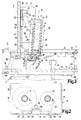
- FIG. 1 schematically shows an oblique view of a recording and reproducing device for a tape-shaped recording medium accommodated in a cassette, which has a pivotable closure cover for closing a receiving space for a cassette holder.
- FIG. 2 shows a cassette, which can be used for recording and reproducing sound signals in the device according to FIG. 3 shows in a schematic manner, according to a section along the line VV in FIG. 1, on an enlarged scale compared to FIG. 1, a part of the device according to FIG. 1 that is essential in connection with the present invention, the closure cover being open Position. 4 shows, analogously to FIG.
- FIG. 3 shows, analogously to FIGS. 3 and 4, in a section along the line VV in FIG. 1, the part of the device according to FIG. 1 essential to the invention, with the closure cover is in its closed position.
- the 1 shows a recording and reproducing device 1, which is provided for recording and reproducing voice signals and is to be referred to as a table dictation device.
- the device 1 has an inclined ceiling wall 2, in the area of which a receiving space 3 is provided for a cassette holder for receiving a cassette. Such a cassette 4 is shown in FIG. 2.
- a pivotable closure cover 5 To close the receiving space 3, the device 1 is provided with a pivotable closure cover 5.
- the device has a pivotable push button 6 which is arranged next to the closure cover and extends over its entire width.
- buttons 7 with four pushbuttons is provided in the area of the ceiling wall 2, with which the operating modes of the device “fast rewind”, “stop”, “playback” and “fast forward” can be switched on from left to right according to FIG.
- the pushbuttons of the key set 7 each interact with an electrical switching contact, each switching contact emitting a switching signal to a microprocessor provided in the device 1, which in turn effects the adjustment of the required device parts for switching on the desired operating mode in accordance with the switching signals via electromagnets or servomotors controlled by it . Since such measures are already known in such devices and are not essential in connection with the present invention, a detailed description thereof is omitted.
- the device 1 To indicate which of the aforementioned operating modes is switched on in the device 1, it has a set 8 of light-emitting diodes which are arranged next to the pushbuttons, each light-emitting diode being assigned to a pushbutton. It should be mentioned that the "recording" operating mode can be switched on from a microphone that can be connected to the device 1 via the microprocessor mentioned, but this is not shown for the sake of simplicity. Furthermore, a pushbutton 9 is provided in the area of the ceiling wall 2, which is to be pressed in order to put the device 1 into operation at all.
- the closure cover 5 of the device 1 has a transparent area through which can be seen through into the receiving space 3, wherein according to FIG. 1 there is no cassette in the receiving space 3.
- the receiving space 3 contains a pivotable cassette holder 10 for receiving a cassette and two winding mandrels 11 and 12, which can be driven by a motor in a manner not shown in detail, and a stationary stop 13 for supporting a cassette brought into an operating position for its vertical positioning.
- the cassette 4 has a cuboid housing with a first main wall 14 lying at the bottom according to FIG. 2, a second main wall 15 lying at the top according to FIG. 2, a long first side wall 16 at the front according to FIG. 2 and a long one at the back according to FIG second side wall 17 and two short side walls 18 and 19.
- a magnetizable, tape-shaped recording medium 20, hereinafter referred to as magnetic tape is housed.
- To wind up the magnetic tape 20 two juxtaposed, rotating drivable winding cores 21 and 22 are rotatably mounted in the cassette 4.
- the magnetic tape 20 is guided from the one winding core 21 via a tape guide 23 along the first side wall 16 and a further tape guide 24 to the other winding core 22. Since the cassette 4 can be inserted in the device 1 in two mutually facing positions in a known manner, the two mandrels 11 and 12 for driving the winding cores 21 and 22 through both main walls 14 and 15 of the cassette are in drive connection with the winding cores 21 and 22 bringable.
- the cassette 4 has two openings coaxial to the winding cores 21 and 22 on each main wall 14 and 15, all four of which are designated by the reference number 25 for the sake of simplicity.
- the cassette 4 has two openings 26 and 27, through which a magnetic head on the device side can be operatively connected to the magnetic tape 20.
- a magnetic head on the device side can be operatively connected to the magnetic tape 20.
- there are two pressure felts 30 fastened in the cassette 4 on a displaceable and pivotable pressure felt carrier 29 loaded with a leg spring 28 and 31 are provided.
- the cassette 4 has in the region of its first side wall 16 two positioning openings 32 and 33, into each of which a stationary positioning stop on the device side can be inserted in order to position the cassette both in its vertical position and in its lateral position with respect to the magnetic heads.
- the cassette receptacle 10 is essentially shaft-shaped and consists of a U-shaped bottom wall 34, two side walls 35 protruding from the legs of the bottom wall 34 and two protruding from the side walls 35, facing each other Ceiling strips 36.
- the cassette holder 10 can be pivoted about a pivot axis 37.
- the pivot axis 37 is defined by two bearing pins 38 which project outwardly from the side walls 35 and are each rotatably mounted in a bearing tab 39.
- the two bearing tabs 39 protrude from a chassis plate 40 delimiting the receiving space 3.
- the cassette receptacle 10 and its pivot bearing are essentially mirror-symmetrical with respect to a plane running perpendicular to their bottom wall 34 and in the shaft direction, which is indicated by an arrow 41 in FIGS. 3 to 5, with the sectional representation in FIGS only half of it can be seen.
- the cassette holder 10 can be pivoted between a loading position shown in FIG. 3 and an operating position shown in FIG.
- FIG. 3 In the loading position shown in FIG. 3, a cassette 4 with the first side wall 16 first in the shaft direction 41 can be inserted into the cassette holder 10 up to an insertion position defined by two limit stops 42 provided on the cassette holder.
- the limit stops 42 are hereby formed by the short arms of two L-shaped angles 43, the long arms of which are connected to the cover strips 36 of the cassette holder 10 and protrude from them in the shaft direction 41.
- FIGS. 3 and 4 show a cassette 4 inserted into the cassette holder 10 in its insertion position.
- an inserted into the cassette holder takes Cassette 4 an operating position, which can be seen from Fig.5.
- the winding mandrels 11 and 12 are in drive connection through the first main wall 14 of the cassette 4 with the winding cores 21 and 22.
- the magnetic heads of the device 1, of which only one magnetic head 44 can be seen in FIGS. 3 to 5 are in contact with the magnetic tape 20 through the openings 26 and 27 in the first side wall 16 of the cassette 4, the magnetic tape 20 is pressed against the magnetic heads with the pressure felts 30 and 31.
- the magnetic heads are adjustably attached to the chassis plate 40, which is not shown in detail in FIGS. 3 to 5 for the sake of simplicity.
- the cassette 4 In the operating position of the cassette 4, the same lies in the area of the first main wall 14, which adjoins the second side wall 17 opposite the first side wall 16, on the stationary stop 13 provided on the chassis plate 40 of the device, the top surface 45 of which is a stop surface for the Cassette 4 forms the same for height positioning, which engages the cassette 4 in the region of the first main wall 14 adjoining the second side wall 17. Furthermore, the cassette 4 in its operating position rests against two stationary positioning stops 46 which protrude from the chassis plate 40 and engage the cassette 4 in the region of the first side wall 16, the positioning stops 46 in the positioning openings 32 and 33 provided for this purpose in the first side wall 16 are introduced.
- the cassette 4 is adjusted against the shaft direction 41 from its insertion position in the cassette receptacle 10 and is held in its operating position in a lifted manner from the limit stops 42 on the cassette receptacle 10.
- the distance between the insertion position and the operating position of the cassette is actually about 0.2 mm; For the sake of clarity, this distance is shown somewhat larger in FIG.
- the pivotable closure cover 5 is arranged essentially adjacent to the second main wall 15 opposite the first main wall 14 of a cassette 4 inserted into the cassette holder 10.
- the closure lid 5 is essentially plate-shaped. It consists of a to Closing the receiving space 3 provided rectangular ceiling plate 47 and two side plates 48 opposite the side walls 35 of the cassette holder 10.
- the closure cover 5 can be pivoted about a pivot axis 49, which is fixed by two bearing pins 50 projecting outwards from the side plates 48, which are located in the housing walls of the Device 1 are rotatably mounted.
- the closure cover 5 and its swivel mounting are mirror-symmetrical in the same way as the cassette holder 10, only a half of which can be seen due to the sectional view in FIGS. 3 to 5.
- the closure cover 5 can be pivoted between an open position shown in FIG. 3 and a closed position shown in FIG.
- the pivoting in the direction of the closed position is limited by a stop bar 51 projecting from the ceiling wall 2 of the housing of the device.
- the pivoting in the direction of the open position is limited by a stop not shown due to the sectional view.
- the closure cover 5 is coupled to the cassette holder 10 for the joint pivoting of the two via two coupling devices 52.
- the coupling devices 52 are formed in a particularly simple manner by two pin-slot connections.
- the pin-slot connections 52 each have a pin 53 projecting outwards from the side walls 35 of the cassette holder 10 and each have a slot 54 provided in the side plates 48 of the closure cover 5, in which the pin 53 can slide with little play.
- the slots 54 have an angled course and at their closed ends a circular extension 55, in which the pins 53 are free from the slots 54, so that in the extensions 55, the position of the cassette holder 10 is relatively independent of the position of the Closure cover 5 can be fixed.
- the pin-slot connections 52 are formed by the above-mentioned choice of the course of the slots 54 so that the closure cover 5 can be pivoted between its open position and its closed position by a pivoting area which is different in size from the pivoting range of the cassette holder 10 between it Loading position and its operating position is.
- the pivoting range of the closure cap 5 is greater than that of the cassette holder 10, so that the closure cap is at a greater distance from the cassette holder in its open position than in its closed position.
- the coupling devices can also be designed differently, for example as a lever mechanism.
- a coupling device can also be designed to be detachable and have a stop surface on the cassette holder and a further stop surface on the closure cover, the two stop surfaces coming into mutual contact when the closure cover is pivoted into its closed position and the cassette holder into its operating position.
- the closure cover 5 is not only provided for closing the receiving space 3, but also forms a pivotable carrier between an initial position and a working position for two adjustable pressure devices 56 arranged on it in mirror symmetry, the open position of the closure cover shown in FIG. 3 being the starting position and the the closed position of the closure cap shown in FIG. 5 corresponds to the working position. Only one of the two pressure devices 56 can be seen in FIGS. 3 to 5 due to the sectional illustration.
- Each pressure device 56 is formed by a pressure slide which is displaceably guided on the closure cover 5 perpendicular to its pivot axis 49 with a pin-slot connection 57.
- the pressure slides can also be slidably guided in other ways, for example with guide strips sliding in guide grooves.
- Each of the two pressure slides 56 is under the action of a tension spring 58 which, on the one hand, engages at one end 59 of the pressure slide and, on the other hand, on an extension 60 projecting from the cover plate 47 of the sealing cover 5.
- An engagement point 61 is provided on each pressure slide 56, by means of which the pressure slide 56 engages the cassette 4 at a corresponding engagement point 62 in the region of the second side wall 17 opposite the first side wall 16 when the pressure slide 56 with the cassette 4 in Active connection is established.
- the pressure slides 56 are in the cassette receptacle 10 in their loading position and the closure lid 5 is in its open position due to the larger pivoting range of the closure lid outside the insertion area of a cassette 4 into the cassette receptacle 10.
- the pressure slides are taken here 56 a rest position in which they are supported under the action of the tension springs 58 acting on them, each on a stop 63 provided on the sealing cap 5.
- the pivot axis 49 of the closure cover 5 is arranged offset parallel to the pivot axis 37 of the cassette holder 10.
- the offset of the pivot axes 37 and 49 of the cassette holder 10 and the closure cover 5 against each other and the rest position of the pressure slide 56 on the closure cover 5 is selected such that the distance of the engagement point 61 provided on each pressure slide 56 from the pivot axis 37 of the cassette holder 10 on the one hand in its loading position of the cassette holder 10 and the closure cover 5 in its open position, the pressure slide 56 being in its rest position, is larger and, on the other hand, when the cassette holder 10 is in its operating position without a cassette inserted therein and the closure cover 5 being in its closed position , wherein the pressure slide 56 are also in their rest position, is smaller than the distance from the corresponding to the attack point 61 provided on each pressure slide 56, located on the cartridge 4 inserted into the cassette holder 10 Riffsstelle 62 from the pivot axis 37 of the cassette holder 10.
- the offset is made in the present device so that when the cassette holder 10 is in its operating position and the closure cover 5 is in its closed position, the normal distance of the pivot axis 49 of the closure cover 5 from the second side wall 17 of a cassette 4 inserted into the cassette holder 10 is greater than the normal distance of the pivot axis 37 of the cassette holder 10 from the second side wall 17.
- the corresponding engagement points 62 on the cassette 4 inserted into the cassette holder 10 are essentially opposite the positioning openings 32 and 33 on the first side wall 16 of the cassette 4.
- the corresponding points of attack 62 lie in the edge region of the cassette 4, into which the second side wall 17 opposite the first side wall 16 and the second main wall 15 opposite the first main wall 14 open.
- the engagement points 61 provided on the pressure slides 56 are provided on an engaging surface 64 of the pressure slides 56, which is inclined with respect to the second side wall 17 opening into this edge area and with respect to the second main wall 15 opening into this edge area.
- the cassette 4 in its operating position is in the area of the first main wall 14 adjacent to the second side wall 17 to that provided on the chassis plate 40 of the device 1 , in the area of the first main wall 14 on the cassette 4 attacking stationary Support surface 45 of the stop 13 is kept laid. Due to the above-described pressing of the cassette 4 against the positioning stops 46 and against the stop 13, the cassette 4 is securely positioned exactly in its operating position, which ensures that voice signals are recorded and reproduced correctly on the magnetic tape accommodated in the cassette by means of the magnetic heads.
- the displacement of the pivot axis 49 of the closure cover 5 and the pivot axis 37 of the cassette holder 10 against one another is selected such that the pivot axis 49 of the closure cover 5 has a larger normal distance from it first main wall 14 of a cassette 4 inserted into the cassette receptacle 10 as the points of attack 61 provided on the pressure slides 56 of the first main wall 14.
- a detachable holding device 65 is provided for holding the closure lid 5 in its closed position against the adjusting forces acting on it.
- the holding device is formed by a locking slide adjustable perpendicular to the pivot axis 49 of the closure cover 5.
- the locking slide 65 is slidably guided between the top wall 2 of the housing of the device and a guide bar 66 between a release position shown in FIGS. 3 and 4 and a locking position shown in FIG. 5, the locking slide 65 under the action of a tension spring acting on it 67 is adjustable in its locking position.
- the pushbutton 6 which has an angled extension 68, on which a return spring 69 engages, which holds the extension 68 against a stop 70 projecting from the chassis plate 40, and the free end thereof cooperate with the opposite end of the locking slide 65 is provided.
- the locking slide 65 carries in the region of its other end a locking projection 71 projecting laterally from it, which engages behind a locking shoulder 72 which is provided on that side plate 48 of the locking cover 5 when the locking cover 5 is in its closed position and the locking slide 65 is in its locked position can be seen in Figures 3 to 5. In this way, the closure cap 5 is securely held in its closed position.
- the cassette receptacle 10 is thereby securely held in its operating position in that a cassette 4 inserted into the cassette receptacle 10 is pressed against the stop 13 by the pressure slides 56 arranged on the fixed closure cover 5, the cassette 4 via the U-shaped bottom wall 34 the cassette holder 10 holds. If there is no cassette in the cassette receptacle 10, the cassette receptacle 10 is held by the latter with the closure cover 5 closed via the pin-slot connections 52, but is then not in its operating position due to the circular extensions 55 of the slots 54, which is irrelevant in this case. At this point it should be mentioned that the cassette holder 10 is held in its loading position according to FIG. 3 by the pin-slot connections 52 when the closure lid 5 is open.
- a tab 73 which is connected thereto and perpendicular to the pivot axis 49 of the closure cover 5 and on which a tension spring is attached 74 attacks, which serves to adjust the cap 5 to its fully open position.
- the free end 75 of the tab 73 has an arcuate, to the pivot axis 49 of the cover 5 coaxial course.
- the locking slide 65 has a circular arc-shaped control surface 76 corresponding to the circular end 75 of the tab 73, via which the locking slide 65 is moved from the circular end 75 of the tab 73 in when the closure cover 5 is in its open position and when the closure cover 5 is pivoted into its closed position its release position is blocked.
- the circular-arc-shaped end 75 of the tab 73 only comes out of operative connection from the circular-arc-shaped control surface 76 of the locking slide 65 before reaching its closed position and releases the locking slide 65 for adjustment into its locking position under the action of the tension spring 67 .
- the position of the locking slide 65 and consequently the function of the same is controlled in dependence on the position of the closing cover 5, so that the locking slide 65 can only come into effect when the closing cover 5 is moved into its closed position . It is furthermore achieved that, when the closure cover 5 is adjusted from its closed position, the locking slide 65 is kept adjusted in its release position, the lock slide 65 in its release position also being able to be used to control other parts of the device which are deactivated when the closure cover 5 is opened should and should be kept inoperative when the cover is open.
- a stop surface 77 is provided which transitions into the locking shoulder 72 and which has an arc-shaped course which is coaxial with the pivot axis 49 of the closure cap 5.
- the locking extension 71 of the locking slide 65 is supported on this stop surface 77 under the action of the tension spring 67 acting on the locking slide after the circular-shaped end 75 of the tab 73 has been removed from the circular-shaped control surface 76 of the locking slide 65 before reaching the closed position of the closure cover 5 is out of operative connection. In this way, proper functioning of the holding device formed by the locking slide 65 is ensured because the locking extension 71 is securely transferred from the stop surface 77 to the adjoining locking shoulder 72.
Description
Die Erfindung bezieht sich auf ein Aufzeichnungs- und/oder Wiedergabegerät für einen bandförmigen Aufzeichnungsträger, der in einer in das Gerät einsetzbaren Kassette mit zwei nebeneinanderliegenden, rotierend antreibbaren Wickelkernen für denselben untergebracht ist, mit rotierend antreibbaren, durch mindestens eine erste Hauptwand der Kassette hindurch mit den Wickelkernen in Antriebsverbindung bringbaren Wickeldornen zum Antreiben der Wickelkerne und mit einer um eine Schwenkachse verschwenkbaren, im wesentlichen schachtförmig ausgebildeten Kassettenaufnahme, die zwischen einer Ladeposition, in der eine Kassette mit einer ersten Seitenwand voran in Schachtrichtung in die Kassettenaufnahme bis in eine durch mindestens einen an der Kassettenaufnahme vorgesehenen Begrenzungsanschlag festgelegte Einführlage einführbar ist, und einer Betriebsposition verschwenkbar ist, in der eine in die Kassettenaufnahme eingeführte Kassette eine Betriebslage einnimmt, in der die Wickeldorne mit den Wickelkernen in Antriebsverbindung stehen, sowie mit mindestens einer unter der Wirkung einer Feder stehenden Andruckeinrichtung, die bei in ihrer Ladeposition befindlicher Kassettenaufnahme sich außerhalb des Einführbereiches einer Kassette in die Kassettenaufnahme befindet und die beim Verschwenken der Kassettenaufnahme in ihre Betriebsposition mit einer in dieselbe eingeführten Kassette in Wirkverbindung tritt, wobei die Andruckeinrichtung mit mindestens einer an ihr vorgesehenen Angriffsstelle an einer zu dieser korrespondierenden, im Bereich der der ersten Seitenwand gegenüberliegenden Seitenwand befindlichen Angriffsstelle an der Kassette angreift und die Kassette unter der Wirkung der auf die Andruckeinrichtung einwirkenden Feder in Schachtrichtung zu dem Begrenzungsanschlag hindrückt.The invention relates to a recording and / or reproducing device for a tape-shaped recording medium, which is accommodated in a cassette that can be inserted into the device with two adjacent, rotatably drivable winding cores for the same, with rotatably drivable through at least a first main wall of the cassette the winding cores in drive connection bringable mandrels for driving the winding cores and with a pivotable about a pivot axis, essentially shaft-shaped cassette holder, which is between a loading position in which a cassette with a first side wall in the direction of the shaft into the cassette holder into at least one the limit stop provided in the cassette receptacle can be inserted, and an operating position can be pivoted in which a cassette inserted into the cassette receptacle assumes an operating position in which the winding mandrels m with the winding cores in drive connection, as well as with at least one pressure device under the action of a spring, which, when the cassette holder is in its loading position, is located outside the insertion area of a cassette into the cassette holder and which, when the cassette holder is pivoted into its operating position, is inserted into one with the same Cassette enters into operative connection, the pressure device engaging with at least one attack point provided on it at a corresponding attack point on the cassette located in the region of the side wall opposite the first side wall and engaging the cassette in the shaft direction under the action of the spring acting on the pressure device the limit stop.
Ein solches Gerät ist aus der AT-PS 298.104 bekannt. Bei diesem bekannten Gerät ist die Andruckeinrichtung feststehend innerhalb des Gerätes angeordnet, wobei sie beim Verschwenken einer in die Kassettenaufnahme eingeführten Kassette in ihre Betriebslage, erst unmittelbar bevor die Kassette ihre Betriebslage erreicht, mit derselben in Wirkverbindung tritt. Wenn bei diesem bekannten Gerät eine Kassette vom Benützer nicht einwandfrei bis in die hier durch zwei Begrenzungsanschläge an der Kassettenaufnahme festgelegte Einführlage in die Kassettenaufnahme eingeführt wird, was beispielsweise bei ungünstigen Reibungsverhältnissen durch Verklemmen der Kassette eintreten kann, kann es beim Verschwenken der nicht einwandfrei eingeführten Kassette in ihre Betriebslage zu Störungen beim Eintauchen der zum Antreiben der beiden Wickelkerne vorgesehenen Wickeldorne in die Kassette kommen, weil dieses Eintauchen der beiden Wickeldorne schon zu einem Zeitpunkt erfolgt, zu dem die Andruckeinrichtung noch nicht mit der Kassette zusammenwirkt und daher die Kassette noch nicht in ihre Einführlage in der Kassettenaufnahme gedrückt und in derselben gehalten wird. Wenn eine Kassette nicht einwandfrei in ihre Einführlage in der Kassettenaufnahme eingeführt ist, kann sogar der Fall eintreten, daß die Kassette mit ihrer ersten Hauptwand, durch die die Wickeldorne hindurch mit den Wickelkernen in Antriebsverbindung bringbar sind, gegen die Wickeldorne stößt, wobei sie dann nicht in ihre Betriebslage verschwenkt und somit das Gerät nicht in Betrieb genommen werden kann. Weiters tritt bei dem bekannten Gerät die feststehend angeordnete Andruckeinrichtung abrupt mit einer in die Kassettenaufnahme eingeführten Kassette in Wirkverbindung, was bei der händischen Verstellung der Kassettenaufnahme vom Benützer als störend empfunden werden kann, da im Bewegungsablauf plötzlich ein Widerstand spürbar wird, und was auch zu einem erhöhten Verschleiß von sowohl der Andruckeinrichtung als auch der Kassette führen kann.Such a device is known from AT-PS 298.104. In this known device, the pressure device is arranged in a fixed manner within the device, and when a cassette inserted into the cassette holder is pivoted into its operating position, it is only immediately before the cassette reaches its operating position reached, in active connection with it. If, in this known device, a cassette is not correctly inserted into the cassette holder by the user into the insertion position defined here by two limit stops on the cassette holder, which can occur, for example, if the cassette is jammed under unfavorable frictional conditions, it can occur when the cassette which is not correctly inserted is pivoted in their operating position to disturbances when immersing the mandrels intended to drive the two winding cores into the cassette, because this immersion of the two mandrels occurs at a time when the pressure device does not yet cooperate with the cassette and therefore does not yet insert the cassette into hers Insertion position in the cassette holder is pressed and held in the same. If a cassette is not correctly inserted into its insertion position in the cassette holder, the case may even occur that the cassette with its first main wall, through which the winding mandrels can be brought into drive connection with the winding cores, abuts against the winding mandrels, in which case it does not swiveled into their operating position and thus the device cannot be put into operation. Furthermore, in the known device, the stationary pressure device abruptly interacts with a cassette inserted into the cassette holder, which can be perceived as disruptive by the user when manually adjusting the cassette holder, since resistance is suddenly felt in the sequence of movements, and what also leads to one increased wear of both the pressure device and the cassette can result.
Die Erfindung hat sich zur Aufgabe gestellt, die vorstehend angeführten Schwierigkeiten zu vermeiden und ein Gerät zu schaffen, bei dem eine in die Kassettenaufnahme eingeführte Kassette bereits zu einem relativ frühen Zeitpunkt des Schwenkvorganges der Kassettenaufnahme in ihre Betriebsposition mit Sicherheit in ihre Einführlage in der Kassettenaufnahme gedrückt und in derselben gehalten wird und bei dem ein abruptes Angreifen der Andruckeinrichtung an der Kassette vermieden ist. Hiefür ist die Erfindung dadurch gekennzeichnet, daß die Andruckeinrichtung an einem um eine Schwenkachse zwischen einer Ausgangsposition und einer Arbeitsposition verschwenkbaren Träger angeordnet ist, daß der Träger mit der Kassettenaufnahme zum zumindest teilweise gemeinsamen Verschwenken der beiden über mindestens eine Kopplungseinrichtung gekoppelt ist und daß die Schwenkachse des Trägers gegenüber der Schwenkachse der Kassettenaufnahme parallel versetzt angeordnet ist, wobei der Abstand der an der Andruckeinrichtung vorgesehenen Angriffsstelle von der Schwenkachse der Kassettenaufnahme einerseits bei in ihrer Ladeposition befindlicher Kassettenaufnahme und dabei in seiner Ausgangsposition befindlichem Träger größer und andererseits bei in ihrer Betriebsposition befindlicher Kassettenaufnahme ohne in sie eingeführter Kassette und dabei in seiner Arbeitsposition befindlichem Träger kleiner ist als der Abstand der an einer in die Kassettenaufnahme eingeführten Kassette befindlichen korrespondierenden Angriffsstelle von der Schwenkachse der Kassettenaufnahme und beim Verschwenken des Trägers von seiner Ausgangsposition in seine Arbeitsposition die an der Andruckeinrichtung vorgesehene Angriffsstelle sich zu der an einer in die Kassettenaufnahme eingeführten Kassette befindlichen korrespondierenden Angriffsstelle hin bewegt und dabei an derselben zum Angreifen kommt. Durch das Anordnen der Andruckeinrichtung an dem verschwenkbaren Träger und durch das wie angeführte gegeneinander Versetzten der Schwenkachsen der Kassettenaufnahme und des Trägers wird beim Verschwenken der beiden in ihre Betriebs- bzw. Arbeitsposition eine Relativbewegung zwischen der am Träger angebrachten Andruckeinrichtung und einer in die Kassettenaufnahme eingeführten Kassette erreicht, der zufolge die beim Verschwenken des Trägers mitbewegte Andruckeinrichtung bereits zu einem relativ frühen Zeitpunkt des Schwenkvorganges mit der Kassette in Wirkverbindung tritt, wodurch die Kassette bereits relativ früh, bevor noch der Schwenkvorgang beendet ist, sicher in ihre Einführlage in der Kassettenaufnahme gedrückt und in derselben gehalten wird, so daß die Wickeldorne mit Sicherheit ohne Schwierigkeiten in die ordnungsgemäß in ihrer Einführlage befindliche Kassette eintauchen können. Weiters ist durch die erfindungsgemäßen Maßnahmen erreicht, daß die Andruckeinrichtung kontinuierlich an eine in die Kassettenaufnahme eingeführte Kassette heranbewegt wird und dabei sanft mit dieser in Wirkverbindung tritt, wobei die von der auf die Andruckeinrichtung einwirkenden Feder auf die Kassette aufgebrachte Kraft kontinuierlich zunimmt, so daß ein gleichmäßiger Bewegungsablauf ohne von einem Benützer spürbare störende Rückwirkungen und ein besonders geringer Verschleiß für die Andruckeinrichtung und die Kassette erreicht wird.The object of the invention is to avoid the difficulties mentioned above and to provide a device in which a cassette inserted into the cassette holder is pressed into its insertion position in the cassette holder at a relatively early point in time when the cassette holder is pivoted into its operating position and is held in the same and in which an abrupt attack of the pressure device on the cassette is avoided. For this, the invention is characterized in that the pressure device on a pivot axis between a starting position and a working position pivotable carrier is arranged, that the carrier is coupled to the cassette holder for at least partially jointly pivoting the two via at least one coupling device and that the pivot axis of the carrier is arranged offset parallel to the pivot axis of the cassette holder, the distance between the at the contact point provided on the pressure device from the pivot axis of the cassette holder is larger on the one hand when the cassette holder is in its loading position and the carrier in its starting position and on the other hand is smaller than the distance when the cassette holder is in its operating position without a cassette inserted into it and the carrier in its working position the corresponding point of attack located on a cassette inserted in the cassette holder from the pivot axis of the cassette holder and when conspiring lower the carrier from its starting position into its working position, the point of attack provided on the pressing device moves towards the corresponding point of attack located on a cassette inserted into the cassette holder and thereby comes to attack the same. The arrangement of the pressure device on the pivotable carrier and the offset of the pivot axes of the cassette holder and the carrier, as mentioned, results in a relative movement between the pressure device attached to the carrier and a cassette inserted into the cassette holder when the two are pivoted into their operating or working position reached, according to which the pressure device moved during pivoting of the carrier already comes into operative connection with the cassette at a relatively early point in the pivoting process, as a result of which the cassette is pressed relatively securely into its insertion position in the cassette holder and in relatively early before the pivoting process has ended the same is held so that the winding mandrels can safely dip into the cassette properly in its insertion position with certainty. It is also achieved by the measures according to the invention that the pressure device is continuously inserted into an inserted into the cassette holder Cassette is moved up and thereby gently interacts with it, the force exerted on the cassette by the spring acting on the pressing device continuously increasing, so that a smooth movement without any noticeable interferences and a particularly low wear and tear for the pressing device and the cassette is reached.
An dieser Stelle sei erwähnt, daß aus der DE-PS 26 36 512 ein Gerät bekannt ist, bei dem mit einer verschwenkbaren Kassettenaufnahme über eine durch eine Stift-Schlitz-Verbindung gebildete Kopplungseinrichtung ein um eine zur Schwenkachse der Kassettenaufnahme parallel versetzt angeordnete Schwenkachse verschwenkbarer, hier zum Öffnen von Kassettendeckeln einer in die Kassettenaufnahme eingeführten Kassette ausgebildeter Träger gekoppelt ist. Dieses Gerät weist keine Andruckeinrichtung zum Hindrücken einer in die Kassettenaufnahme eingeführten Kassette zu mindestens einem an der Kassettenaufnahme vorgesehenen Begrenzungsanschlag auf. Bei diesem bekannten Gerät sind vielmehr an dem Träger zwei feststehende Stifte angeordnet, mit denen beim Verschwenken der Kassettenaufnahme in ihre Betriebsposition durch die hiebei auftretende, durch das gegeneinander Versetzen der Schwenkachsen der Kassettenaufnahme und des Trägers erzielte Relativbewegung, wie erwähnt, zwei Kassettendeckel einer in die Kassettenaufnahme eingeführten Kassette geöffnet werden. Dagegen ist beim erfindungsgemäßen Gerät am Träger mindestens eine unter der Wirkung einer Feder stehende Andruckeinrichtung angeordnet, die zum Hindrücken einer in die Kassettenaufnahme eingeführten Kassette zu mindestens einem an der Kassettenaufnahme vorgesehenen Begrenzungsanschlag dient. Somit handelt es sich bei dem aus der DE-PS 26 36 512 bekannten Gerät um ein sowohl hinsichtlich der konstruktiven Merkmale als auch in funktioneller Hinsicht gegenüber einem erfindungsgemäßen Gerät unterschiedliches Gerät, bei dem demgemäß die erfindungsgemäßen Vorteile nicht gegeben beziehungsweise erreichbar sind.At this point it should be mentioned that from DE-PS 26 36 512 a device is known in which, with a pivotable cassette receptacle via a coupling device formed by a pin-slot connection, a pivot axis pivotable about a pivot axis offset parallel to the pivot axis of the cassette holder, here a carrier designed for insertion of cassette covers is inserted into the cassette holder. This device does not have a pressure device for pressing a cassette inserted into the cassette holder to at least one limit stop provided on the cassette holder. Rather, in this known device, two fixed pins are arranged on the carrier, with which, when mentioned, the two movement of the cassette receptacle into its operating position due to the relative movement achieved by displacing the pivoting axes of the cassette receptacle and the carrier, as mentioned, two cassette covers into one Cassette holder inserted cassette can be opened. In contrast, in the device according to the invention, at least one pressure device, which is under the action of a spring, is arranged on the carrier and serves to press a cassette inserted into the cassette holder to at least one limit stop provided on the cassette holder. Thus, the device known from DE-PS 26 36 512 is a device which is different both in terms of design features and in terms of function compared to a device according to the invention, in which the advantages according to the invention are accordingly not given or achievable.
Bei einem erfindungsgemäßen Gerät kann beispielsweise der Träger zu der ersten Hauptwand einer in die Kassettenaufnahme eingeführten Kassette benachbart angeordnet sein. Auch können zwei beispielsweise im wesentlichen L-förmige Träger für je eine Andruckeinrichtung vorgesehen sein, von denen je einer zu einer der beiden zu der ersten Seitenwand senkrecht verlaufenden Seitenwände benachbart angeordnet ist. Als vorteilhaft hat sich aber erwiesen, wenn der Träger im wesentlichen zu der der ersten Hauptwand gegenüberliegenden Hauptwand einer in die Kassettenaufnahme eingeführten Kassette benachbart angeordnet ist. Auf diese Weise ist eine einfache und raumsparende Ausbildung erreicht.In a device according to the invention, for example, the carrier can be arranged adjacent to the first main wall of a cassette inserted into the cassette holder. Also two, for example, substantially L-shaped carriers for each a pressure device may be provided, one of which is arranged adjacent to one of the two side walls running perpendicular to the first side wall. However, it has proven to be advantageous if the carrier is arranged essentially adjacent to the main wall opposite the first main wall of a cassette inserted into the cassette holder. In this way, simple and space-saving training is achieved.
In diesem Zusammenhang hat sich als besonders vorteilhaft erwiesen, wenn der Träger im wesentlichen plattenförmig ausgebildet ist und einen Verschlußdeckel für einen die Kassettenaufnahme in ihrer Betriebsposition aufnehmenden Aufnahmeraum bildet. Hiedurch erfüllt der Träger nicht nur seine Trägerfunktion für die Andruckeinrichtung, sondern auch eine zusätzliche Verschlußfunktion für einen Aufnahmeraum für die Kassettenaufnahme in ihrer Betriebsposition, so daß sich ein separater Verschlußdeckel für einen solchen Aufnahmeraum erübrigt.In this context, it has proven to be particularly advantageous if the carrier is essentially plate-shaped and forms a closure cover for a receiving space which receives the cassette holder in its operating position. In this way, the carrier not only fulfills its carrier function for the pressure device, but also an additional closure function for a receiving space for the cassette holder in its operating position, so that a separate closure cover for such a receiving space is unnecessary.
Im Hinblick auf die Anordnung der Schwenkachse des Trägers hat sich als vorteilhaft erwiesen, wenn die Schwenkachse des Trägers einen größeren Normalabstand von der ersten Hauptwand einer in die Kassettenaufnahme eingeführten Kassette als die an der Andruckeinrichtung vorgesehene Angriffsstelle aufweist und zum Festhalten des Trägers in seiner Arbeitsposition eine lösbare Festhalteeinrichtung vorgesehen ist. Auf diese Weise ist erreicht, daß bei an einer in die Kassettenaufnahme eingeführten Kassette angreifender Andruckeinrichtung die in Reaktion auf die Federkraft der auf die Andruckeinrichtung einwirkenden Feder an der Andruckeinrichtung auftretende Reaktionskraft an dem Träger ein Drehmoment zur Folge hat, das bestrebt ist, den Träger von seiner Arbeitsposition in seine Ausgangsposition zu verschwenken. Es wird somit vorteilhafterweise die auf die Andruckeinrichtung einwirkende Feder nicht nur zum Liefern der Kraft der Andruckeinrichtung zum Hindrücken einer in die Kassettenaufnahme eingeführten Kassette zu mindestens einem an der Kassettenaufnahme vorgesehenen Begrenzungsanschlag, sondern zusätzlich auch zum Liefern einer Verstellkraft zum Verstellen des Trägers aus seiner Arbeitsposition in seine Ausgangsposition ausgenützt, wodurch das Verschwenken der Kassettenaufnahme in ihre Ladeposition und des Trägers in seine Ausgangsposition von dieser Feder unterstützt wird.With regard to the arrangement of the pivot axis of the carrier, it has proven to be advantageous if the pivot axis of the carrier has a larger normal distance from the first main wall of a cassette inserted into the cassette receptacle than the point of attack provided on the pressing device and one for holding the carrier in its working position releasable holding device is provided. In this way it is achieved that, when a pressure device engages in a cassette inserted into the cassette holder, the reaction force occurring on the pressure device in response to the spring force of the spring acting on the pressure device results in a torque on the carrier which the carrier tends to to pivot from its working position to its starting position. Thus, the spring acting on the pressing device advantageously becomes not only for supplying the force of the pressing device for pressing a cassette inserted into the cassette holder to at least one limit stop provided on the cassette holder, but also for supplying an adjusting force for moving the carrier from its working position in exploited its starting position, whereby the pivoting of the cassette holder into its loading position and the carrier into its starting position is supported by this spring.
Bei einem solchen Gerät kann als Festhalteeinrichtung beispielsweise eine lösbare Rasteinrichtung oder ein verschwenkbarer Verriegelungshebel vorgesehen sein. Als besonders vorteilhaft hat sich aber erwiesen, wenn die Festhalteeinrichtung für den Träger durch einen senkrecht zur Schwenkachse des Trägers verstellbaren Verriegelungsschieber gebildet ist, der unter der Wirkung einer Feder in seine Verriegelungslage verstellbar ist. Hiedurch ist eine besonders einfache und betriebssichere Ausbildung erreicht.In such a device, for example, a releasable locking device or a pivotable locking lever can be provided as the holding device. It has proven to be particularly advantageous, however, if the retaining device for the carrier is formed by a locking slide which is adjustable perpendicularly to the pivot axis of the carrier and which can be adjusted into its locking position under the action of a spring. A particularly simple and reliable training is achieved in this way.
Die an dem Träger angeordnete Andruckeinrichtung kann beispielsweise so wie bei dem aus der eingangs erwähnten AT-PS 298.104 bekannten Gerät aus einem an einer abgewinkelten Blattfeder angebrachten, im wesentlichen halbkugelförmigen Andrucknocken bestehen, wobei die Blattfeder am Träger befestigt ist. Auch kann die Andruckeinrichtung durch einen am Träger verschwenkbar gelagerten Andruckhebel gebildet sein. Als besonders vorteilhaft hat sich aber erwiesen, wenn die Andruckeinrichtung durch einen am Träger senkrecht zu dessen Schwenkachse verschiebbar geführten Andruckschieber gebildet ist. Hiedurch wird eine besonders einfache und betriebssichere Ausbildung erreicht, bei der die Andruckeinrichtung vorteilhafterweise über einen relativ großen Hubbereich verstellbar ist.The pressure device arranged on the carrier can, for example, as in the device known from the aforementioned AT-PS 298.104, consist of an essentially hemispherical pressure cam attached to an angled leaf spring, the leaf spring being fastened to the carrier. The pressure device can also be formed by a pressure lever mounted pivotably on the carrier. However, it has proven to be particularly advantageous if the pressure device is formed by a pressure slide that is displaceably guided on the carrier perpendicular to its pivot axis. A particularly simple and reliable design is achieved in this way, in which the pressure device can advantageously be adjusted over a relatively large stroke range.
Im Zusammenhang mit einer genauen Positionierung einer in ihrer Betriebslage befindlichen Kassette hat sich als vorteilhaft erwiesen, wenn bei in seiner Arbeitsposition befindlichem Träger mit der Andruckeinrichtung eine in ihrer Betriebslage befindliche Kassette an mindestens einen geräteseitigen, im Bereich der ersten Seitenwand an der Kassette angreifenden stationären Positionieranschlag angelegt gehalten ist, wobei die Kassette entgegen der Schachtrichtung aus ihrer Einführlage in der Kassettenaufnahme verstellt und dabei von dem Begrenzungsanschlag an der Kassettenaufnahme abgehoben in ihrer Betriebslage gehalten ist. Auf diese Weise ist erreicht, daß die Andruckeinrichtung nicht nur dafür sorgt, daß eine in die Kassettenaufnahme eingeführte Kassette beim Verschwenken der Kassettenaufnahme in ihre Betriebsposition sicher in ihre Einführlage in der Kassettenaufnahme gedrückt und in derselben während des Verschwenkens der Kassettenaufnahme gehalten wird, sondern daß die Andruckeinrichtung zusätzlich auch dafür sorgt, daß die Kassette anschließend an das Verschwenken der Kassettenaufnahme eine genau definierte Betriebslage einnimmt, die durch das Zusammenwirken ihrer ersten Seitenwand mit dem geräteseitigen stationären Positionieranschlag festgelegt ist, wie dies bei derartigen Geräten zur genauen Positionierung einer Kassette vielfach üblich ist.In connection with a precise positioning of a cassette in its operating position, it has proven to be advantageous if, with the support in its working position, the cassette in its operating position with at least one stationary positioning stop on the device, which engages the cassette in the region of the first side wall is held in place, the cassette being adjusted against the direction of the shaft from its insertion position in the cassette receptacle and being held in its operating position in a lifted manner from the limit stop on the cassette receptacle. In this way it is achieved that the pressure device not only ensures that a cassette inserted into the cassette holder when the cassette holder is pivoted into its operating position, it is securely pressed into its insertion position in the cassette holder and is held in the same during the pivoting of the cassette holder, but that the pressure device additionally also ensures that the cassette assumes a precisely defined operating position after the pivoting of the cassette holder, which is determined by the interaction of its first side wall with the device-side stationary positioning stop, as is common in such devices for the exact positioning of a cassette.
Die an dem Träger angeordnete Andruckeinrichtung kann so ausgebildet sein, daß sie mit ihrer an der korrespondierenden Angriffsstelle an einer in die Kassettenaufnahme eingeführten Kassette angreifenden Angriffsstelle eine ausschließlich in Schachtrichtung ausgerichtete Kraft auf die der ersten Seitenwand gegenüberliegende Seitenwand ausübt, wie dies bei dem aus der eingangs erwähnten AT-PS 298.104 bekannten Gerät der Fall ist. Im Zusammenhang mit einer genauen Positionierung einer in ihrer Betriebslage befindlichen Kassette hat sich aber als vorteilhaft erwiesen, wenn die an einer in die Kassettenaufnahme eingeführten Kassette befindliche korrespondierende Angriffsstelle in dem Kantenbereich der Kassette liegt, in den die der ersten Seitenwand gegenüberliegende Seitenwand und die der ersten Hauptwand gegenüberliegende Hauptwand mündet, und die an der Andruckeinrichtung vorgesehene Angriffsstelle an einer gegenüber der in diesen Kantenbereich mündenden Seitenwand und gegenüber der in diesen Kantenbereich mündenden Hauptwand geneigt verlaufenden Angriffsfläche der Andruckeinrichtung vorgesehen ist und bei in seiner Arbeitsposition befindlichem Träger mit der Andruckeinrichtung eine in ihrer Betriebslage befindliche Kassette in dem an die der ersten Seitenwand gegenüberliegende Seitenwand angrenzenden Bereich ihrer ersten Hauptwand an mindestens eine geräteseitige stationäre Auflagefläche angelegt gehalten ist. Auf diese Weise ist erreicht, daß die Andruckeinrichtung nicht nur dafür sorgt, daß eine in die Kassettenaufnahme eingeführte Kassette beim Verschwenken der Kassettenaufnahme in ihre Betriebsposition sicher in ihre Einführlage in der Kassettenaufnahme gedrückt und in derselben während des Verschwenkens der Kassettenaufnahme gehalten wird, sondern daß die Andruckeinrichtung nach dem Verschwenken der Kassettenaufnahme zusätzlich auch dafür sorgt, daß die in ihrer Betriebslage befindliche Kassette mit ihrem an die der ersten Seitenwand gegenüberliegenden Seitenwand angrenzenden Bereich ihrer ersten Hauptwand mit Sicherheit genau positioniert wird, wie dies bei derartigen Geräten zur genauen Positionierung einer Kassette ebenfalls vielfach üblich ist. Weiters ist dadurch erreicht, daß keine separate Niederhalteeinrichtung, wie beispielsweise mindestens eine an der Kassettenaufnahme angebrachte, gegen die der ersten Hauptwand gegenüberliegende Hauptwand drückende Blattfeder, zum Andrücken der Kassette an die stationäre Auflagefläche erforderlich ist, was im Hinblick auf eine einfache und preisgünstige Ausbildung vorteilhaft ist.The pressure device arranged on the carrier can be designed such that it exerts a force directed exclusively in the direction of the shaft onto the side wall opposite the first side wall, as with the one from the entrance, with its point of attack acting on the corresponding point of attack at a cassette inserted into the cassette holder AT-PS 298.104 known device is the case. In connection with a precise positioning of a cassette in its operating position, it has proven to be advantageous if the corresponding point of attack on a cassette inserted into the cassette holder lies in the edge region of the cassette into which the side wall opposite the first side wall and that of the first The main wall opposite the main wall opens, and the contact point provided on the pressure device is provided on a contact surface of the pressure device which runs inclined with respect to the side wall opening into this edge area and with respect to the main wall opening into this edge area, and with the pressure device in its working position, the support device has one in its operating position located cassette in the area of its first main wall adjacent to the side wall opposite the first side wall to at least one device-side stationary support surface is held. In this way it is achieved that the pressure device not only ensures that a cassette inserted into the cassette receptacle when the cassette receptacle is pivoted into its operating position safely into its insertion position in the cassette receptacle pressed and held in the same during the pivoting of the cassette holder, but that the pressing device after pivoting the cassette holder additionally also ensures that the cassette in its operating position with its region adjacent to the first side wall of its first main wall is certainly accurate is positioned, as is also common in such devices for precise positioning of a cassette. It is also achieved that no separate hold-down device, such as at least one leaf spring attached to the cassette receptacle, pressing against the main wall opposite the first main wall, is required to press the cassette against the stationary support surface, which is advantageous in view of a simple and inexpensive design is.
Die Erfindung wird im folgenden anhand der Zeichnungen näher beschrieben, in denen ein Ausführungsbeispiel der Erfindung dargestellt ist, auf das dieselbe jedoch nicht beschränkt sein soll. Die Fig.1 zeigt schematisch in einer Schrägansicht ein Aufzeichnungs- und Wiedergabegerät für einen in einer Kassette untergebrachten bandförmigen Aufzeichnungsträger, das zum Verschließen eines Aufnahmeraumes für eine Kassettenaufnahme einen verschwenkbaren Verschlußdeckel aufweist. Die Fig.2 zeigt in Draufsicht in etwa zweifacher Vergrößerung eine Kassette, die zum Aufzeichnen und Wiedergeben von Tonsignalen in das Gerät gemäß Figur 1 einsetzbar ist. Die Fig.3 zeigt in schematischer Weise entsprechend einem Schnitt gemäß der Linie V-V in Fig.1 in einem gegenüber Fig.1 vergrößerten Maßstab einen im Zusammenhang mit der vorliegenden Erfindung wesentlichen Teil des Gerätes gemäß Fig.1, wobei der Verschlußdeckel sich in seiner geöffneten Position befindet. Die Fig.4 zeigt analog wie die Fig.3 den erfindungswesentlichen Teil des Gerätes gemäß Fig.1, wobei der Verschlußdeckel sich in einer Zwischenposition zwischen seiner geöffneten und seiner geschlossenen Position befindet. Die Fig.5 zeigt analog wie die Figuren 3 und 4 in einem Schnitt gemäß der Linie V-V in Fig.1 den erfindungswesentlichen Teil des Gerätes gemäß Fig.1, wobei der Verschlußdeckel sich in seiner geschlossenen Position befindet.The invention is described in more detail below with reference to the drawings, in which an embodiment of the invention is shown, to which, however, the same should not be limited. 1 schematically shows an oblique view of a recording and reproducing device for a tape-shaped recording medium accommodated in a cassette, which has a pivotable closure cover for closing a receiving space for a cassette holder. FIG. 2 shows a cassette, which can be used for recording and reproducing sound signals in the device according to FIG. 3 shows in a schematic manner, according to a section along the line VV in FIG. 1, on an enlarged scale compared to FIG. 1, a part of the device according to FIG. 1 that is essential in connection with the present invention, the closure cover being open Position. 4 shows, analogously to FIG. 3, the part of the device according to FIG. 1 which is essential to the invention, the closure cover being in an intermediate position between its open and its closed position. 5 shows, analogously to FIGS. 3 and 4, in a section along the line VV in FIG. 1, the part of the device according to FIG. 1 essential to the invention, with the closure cover is in its closed position.
Die Fig.1 zeigt ein Aufzeichnungs- und Wiedergabegerät 1, das zum Aufzeichnen und Wiedergeben von Sprachsignalen vorgesehen und als Tischdiktiergerät zu bezeichnen ist. Das Gerät 1 weist eine geneigt verlaufende Deckenwand 2 auf, in deren Bereich ein Aufnahmeraum 3 für eine Kassettenaufnahme zum Aufnehmen einer Kassette vorgesehen ist. Eine solche Kassette 4 ist in der Fig. 2 dargestellt. Zum Verschließen des Aufnahmeraumes 3 ist das Gerät 1 mit einem verschwenkbaren Verschlußdeckel 5 versehen. Zum Öffnen des Verschlußdeckels 5 weist das Gerät eine neben dem Verschlußdeckel angeordnete, sich über dessen gesamte Breite erstreckende verschwenkbare Drucktaste 6 auf. Weiters ist im Bereich der Deckenwand 2 ein Tastensatz 7 mit vier Drucktasten vorgesehen , mit denen gemäß Fig.1 von links nach rechts die Betriebsarten des Gerätes "Schneller Rücklauf", "Stop" , "Wiedergabe" und "Schneller Vorlauf" einschaltbar sind. Die Drucktasten des Tastensatzes 7 wirken je mit einem elektrischen Schaltkontakt zusammen, wobei jeder Schaltkontakt ein Schaltsignal an einen im Gerät 1 vorgesehenen Mikroprozessor abgibt, der seinerseits entsprechend den Schaltsignalen über von ihm angesteuerte Elektromagnete beziehungsweise Servomotore das Verstellen der erforderlichen Geräteteile zum Einschalten der gewünschten Betriebsart bewirkt. Da solche Maßnahmen bei derartigen Geräten bereits bekannt und im Zusammenhang mit der vorliegenden Erfindung nicht wesentlich sind, wird auf eine detaillierte Beschreibung derselben verzichtet. Zum Anzeigen, welche der vorgenannten Betriebsarten im Gerät 1 eingeschaltet ist, weist dasselbe einen Satz 8 von Leuchtdioden auf, die neben den Drucktasten angeordnet sind, wobei jede Leuchtdiode einer Drucktaste zugeordnet ist. Erwähnt sei, daß die Betriebsart "Aufnahme" von einem an das Gerät 1 anschließbaren Mikrofon her über den erwähnten Mikroprozessor einschaltbar ist, was der Einfachheit halber aber nicht dargestellt ist. Weiters ist im Bereich der Deckenwand 2 noch eine Drucktaste 9 vorgesehen, die zu betätigen ist, um das Gerät 1 überhaupt in Betrieb zu setzen.1 shows a recording and reproducing
Wie aus Fig.1 ersichtlich ist, weist der Verschlußdeckel 5 des Gerätes 1 einen durchsichtigen Bereich auf, durch den hindurch in den Aufnahmeraum 3 gesehen werden kann, wobei gemäß Fig.1 sich keine Kassette in dem Aufnahmeraum 3 befindet. Der Aufnahmeraum 3 beinhaltet eine verschwenkbare Kassettenaufnahme 10 zum Aufnehmen einer Kassette und zwei auf nicht näher dargestellte Weise motorisch antreibbare Wickeldorne 11 und 12 und einen stationären Anschlag 13 zum Unterstützen einer in eine Betriebslage gebrachten Kassette zu deren höhenmäßiger Positionierung.As can be seen from FIG. 1, the
Im folgenden ist kurz auf die in Fig.2 dargestellte quaderförmige Kassette 4 näher eingegangen, die als Diktierkassette seit langem bekannt ist. Die Kassette 4 weist ein quaderförmiges Gehäuse mit einer gemäß Fig.2 unten liegenden ersten Hauptwand 14, einer gemäß Fig.2 oben liegenden zweiten Hauptwand 15, einer gemäß Fig. 2 vorne liegenden langen ersten Seitenwand 16, einer gemäß Fig.2 hinten liegenden langen zweiten Seitenwand 17 und zwei kurzen Seitenwänden 18 und 19 auf. In der Kassette 4 ist ein magnetisierbarer, bandförmiger Aufzeichnungsträger 20, der im folgenden kurz Magnetband genannt ist, untergebracht. Zum Aufwickeln des Magnetbandes 20 sind in der Kassette 4 zwei nebeneinanderliegende, rotierende antreibbare Wickelkerne 21 und 22 drehbar gelagert. Das Magnetband 20 ist von dem einen Wickelkern 21 über eine Bandführung 23 längs der ersten Seitenwand 16 und eine weitere Bandführung 24 zu dem anderen Wickelkern 22 geführt. Da die Kassette 4 in bekannter Weise in zwei zueinander gewendeten Lagen in das Gerät 1 einsetzbar ist, sind die beiden Wickeldorne 11 und 12 zum Antreiben der Wickelkerne 21 und 22 durch beide Hauptwände 14 und 15 der Kassette hindurch mit den Wickelkernen 21 und 22 in Antriebsverbindung bringbar. Hiefür weist die Kassette 4 an jeder Hauptwand 14 bzw. 15 zwei zu den Wickelkernen 21 und 22 koaxiale Öffnungen auf, die der Einfachheit halber alle vier mit dem Bezugszeichen 25 bezeichnet sind. Im Bereich der ersten Seitenwand 16 weist die Kassette 4 zwei Öffnungen 26 und 27 auf, durch die hindurch je ein geräteseitiger Magnetkopf mit dem Magnetband 20 in Wirkverbindung bringbar ist. Zum Andrücken des Magnetbandes 20 an die Magnetköpfe sind in der Kassette 4 zwei auf einem verschiebbaren und verschwenkbaren, mit einer Schenkelfeder 28 belasteten Andruckfilzträger 29 befestigte Andruckfilze 30 und 31 vorgesehen. Weiters weist die Kassette 4 im Bereich ihrer ersten Seitenwand 16 zwei Positionieröffnungen 32 und 33 auf, in die je ein geräteseitiger stationärer Positionieranschlag einführbar ist, um die Kassette sowohl in ihrer Höhenlage als auch in ihrer Seitenlage gegenüber den Magnetköpfen zu positionieren.The
Wie aus den Figuren 3 bis 5 ersichtlich ist, ist die Kassettenaufnahme 10 im wesentlichen schachtförmig ausgebildet und besteht aus einer U-förmig ausgebildeten Bodenwand 34, zwei von den Schenkeln der Bodenwand 34 abstehenden Seitenwänden 35 und zwei von den Seitenwänden 35 abstehenden, zueinander hin gerichteten Deckenleisten 36. Die Kassettenaufnahme 10 ist um eine Schwenkachse 37 verschwenkbar. Die Schwenkachse 37 ist durch zwei von den Seitenwänden 35 nach außen abstehende Lagerzapfen 38 festgelegt, die je in einem Lagerlappen 39 drehbar gelagert sind. Die beiden Lagerlappen 39 stehen von einer den Aufnahmeraum 3 begrenzenden Chassisplatte 40 ab. Die Kassettenaufnahme 10 und ihre Schwenklagerung sind bezüglich einer senkrecht zu ihrer Bodenwand 34 und in der Schachtrichtung, die in den Figuren 3 bis 5 mit einem Pfeil 41 angegeben ist, verlaufenden Ebene im wesentlichen spiegelsymmetrisch ausgebildet, wobei aufgrund der Schnittdarstellung in den Figuren 3 bis 5 nur eine Hälfte davon zu sehen ist. Die Kassettenaufnahme 10 ist zwischen einer in Fig.3 dargestellten Ladeposition und einer in Fig.5 dargestellten Betriebsposition verschwenkbar.As can be seen from FIGS. 3 to 5, the
In der in Fig.3 dargestellten Ladeposition ist eine Kassette 4 mit der ersten Seitenwand 16 voran in Schachtrichtung 41 in die Kassettenaufnahme 10 bis in eine durch zwei an der Kassettenaufnahme vorgesehene Begrenzungsanschläge 42 festgelegte Einführlage einführbar. Die Begrenzungsanschläge 42 sind hiebei durch die kurzen Arme von zwei L-förmigen Winkeln 43 gebildet, deren lange Arme mit den Deckenleisten 36 der Kassettenaufnahme 10 verbunden sind und von diesen in Schachtrichtung 41 abstehen. In den Figuren 3 und 4 ist eine in die Kassettenaufnahme 10 eingeführte Kassette 4 in ihrer Einführlage befindlich dargestellt.In the loading position shown in FIG. 3, a
In der in Fig.5 dargestellten Betriebsposition der Kassettenaufnahme 10 nimmt eine in die Kassettenaufnahme eingeführte Kassette 4 eine Betriebslage ein, die aus Fig.5 ersichtlich ist. In dieser Betriebslage der Kassette stehen die Wickeldorne 11 und 12 durch die erste Hauptwand 14 der Kassette 4 hindurch mit den Wickelkernen 21 und 22 in Antriebsverbindung. Weiters stehen die Magnetköpfe des Gerätes 1, von denen in den Figuren 3 bis 5 nur ein Magnetkopf 44 zu sehen ist, durch die Öffnungen 26 und 27 in der ersten Seitenwand 16 der Kassette 4 hindurch mit dem Magnetband 20 in Kontakt, wobei das Magnetband 20 mit den Andruckfilzen 30 und 31 gegen die Magnetköpfe gedrückt wird. Die Magnetköpfe sind an der Chassisplatte 40 justierbar befestigt, was in den Figuren 3 bis 5 der Einfachheit halber nicht im Detail dargestellt ist. In der Betriebslage der Kassette 4 liegt dieselbe in dem Bereich der ersten Hauptwand 14, der an die der ersten Seitenwand 16 gegenüberliegende zweite Seitenwand 17 angrenzt, an dem an der Chassisplatte 40 des Gerätes vorgesehenen stationären Anschlag 13 an, dessen Deckfläche 45 eine Anschlagfläche für die Kassette 4 zur Höhenpositionierung derselben bildet, die in dem an die zweite Seitenwand 17 angrenzenden Bereich der ersten Hauptwand 14 an der Kassette 4 angreift. Weiters liegt die in ihrer Betriebslage befindliche Kassette 4 an zwei von der Chassisplatte 40 abstehenden, im Bereich der ersten Seitenwand 16 an der Kassette 4 angreifenden stationären Positionieranschlägen 46 an, wobei die Positionieranschläge 46 in die hiefür in der ersten Seitenwand 16 vorgesehenen Positionieröffnungen 32 und 33 eingeführt sind. Hiebei ist die Kassette 4 entgegen der Schachtrichtung 41 aus ihrer Einführlage in der Kassettenaufnahme 10 verstellt und dabei von den Begrenzungsanschlägen 42 an der Kassettenaufnahme 10 abgehoben in ihrer Betriebslage gehalten. Der Abstand zwischen der Einführlage und der Betriebslage der Kassette beträgt tatsächlich etwa 0,2mm; der Deutlichkeit halber ist dieser Abstand in Fig.5 etwas größer dargestellt.In the operating position of the
Wie aus den Figuren 3 bis 5 weiters ersichtlich ist, ist der verschwenkbare Verschlußdeckel 5 im wesentlichen zu der der ersten Hauptwand 14 gegenüberliegenden zweiten Hauptwand 15 einer in die Kassettenaufnahme 10 eingeführten Kassette 4 benachbart angeordnet. Der Verschlußdeckel 5 ist im wesentlichen plattenförmig ausgebildet. Er besteht aus einer zum Verschließen des Aufnahmeraumes 3 vorgesehenen rechteckförmigen Deckenplatte 47 und zwei den Seitenwänden 35 der Kassettenaufnahme 10 gegenüberliegenden Seitenplatten 48. Der Verschlußdeckel 5 ist um eine Schwenkachse 49 verschwenkbar, die durch zwei von den Seitenplatten 48 nach außen abstehende Lagerzapfen 50 festgelegt ist, die in den Gehäusewänden des Gerätes 1 drehbar gelagert sind. Der Verschlußdeckel 5 und seine Schwenklagerung sind analog wie die Kassettenaufnahme 10 spiegelsymmetrisch ausgebildet, wobei aufgrund der Schnittdarstellung in den Figuren 3 bis 5 nur eine Hälfte davon zu sehen ist. Der Verschlußdeckel 5 ist zwischen einer in Fig.3 dargestellten geöffneten Position und einer in Fig.5 dargestellten geschlossenen Position verschwenkbar. Das Verschwenken in Richtung zur geschlossenen Position ist durch eine von der Deckenwand 2 des Gehäuses des Gerätes abstehende Anschlagleiste 51 begrenzt. Das Verschwenken in Richtung zur geöffneten Position ist durch einen aufgrund der Schnittdarstellung nicht gezeichneten Anschlag begrenzt.As can also be seen from FIGS. 3 to 5, the
Der Verschlußdeckel 5 ist mit der Kassettenaufnahme 10 zum gemeinsamen Verschwenken der beiden über zwei Kopplungseinrichtungen 52 gekoppelt. Die Kopplungseinrichtungen 52 sind auf besonders einfache Weise durch zwei Stift-Schlitz-Verbindungen gebildet. Die Stift-Schlitz-Verbindungen 52 weisen je einen von den Seitenwänden 35 der Kassettenaufnahme 10 nach außen abstehenden Stift 53 und je einen in den Seitenplatten 48 des Verschlußdeckels 5 vorgesehenen Schlitz 54 auf, in dem der Stift 53 mit geringem Spiel gleiten kann. Die Schlitze 54 weisen einen abgewinkelten Verlauf und an ihren geschlossenen Enden eine kreisförmige Erweiterung 55 auf, in der die Stifte 53 von den Schlitzen 54 freigestellt sind, so daß bei in den Erweiterungen 55 liegenden Stiften die Position der Kassettenaufnahme 10 relativ unabhängig von der Position des Verschlußdeckels 5 festlegbar ist. Die Stift-Schlitz-Verbindungen 52 sind durch die vorstehend angeführte Wahl des Verlaufes der Schlitze 54 so ausgebildet, daß der Verschlußdeckel 5 zwischen seiner geöffneten Position und seiner geschlossenen Position um einen Verschwenkbereich verschwenkbar ist, der unterschiedlich groß gegenüber dem Schwenkbereich der Kassettenaufnahme 10 zwischen ihrer Ladeposition und ihrer Betriebsposition ist. Bei vorliegendem Gerät ist der Schwenkbereich des Verschlußdeckels 5 größer als jener der Kassettenaufnahme 10, so daß der Verschlußdeckel in seiner geöffneten Position einen größeren Abstand von der Kassettenaufnahme einnimmt als in seiner geschlossenen Position. Die Kopplungseinrichtungen können auch anders ausgebildet sein, beispielsweise als Hebelmechanismus. Auch kann eine Kopplungseinrichtung lösbar ausgebildet sein und eine Anschlagfläche an der Kassettenaufnahme und eine weitere Anschlagfläche an dem Verschlußdeckel aufweisen, wobei die beiden Anschlagflächen beim Verschwenken des Verschlußdeckels in seine geschlossene Position und der Kassettenaufnahme in ihre Betriebsposition in gegenseitige Anlage kommen.The
Der Verschlußdeckel 5 ist nicht nur zum Verschließen des Aufnahmeraumes 3 vorgesehen, sondern bildet zusätzlich einen zwischen einer Ausgangsposition und einer Arbeitsposition verschwenkbaren Träger für zwei an ihm spiegelsymmetrisch angeordnete verstellbare Andruckeinrichtungen 56, wobei die in Fig.3 dargestellte geöffnete Position des Verschlußdeckels der Ausgangsposition und die in Fig.5 dargestellte geschlossene Position des Verschlußdeckels der Arbeitsposition entspricht. Von den beiden Andruckeinrichtungen 56 ist in den Figuren 3 bis 5 aufgrund der Schnittdarstellung nur eine zu sehen. Jede Andruckeinrichtung 56 ist durch einen am Verschlußdeckel 5 senkrecht zu dessen Schwenkachse 49 mit einer Stift-Schlitz-Verbindung 57 verschiebbar geführten Andruckschieber gebildet. Die Andruckschieber können auch auf andere Weise verschiebbar geführt sein, beispielsweise mit in Führungsnuten gleitenden Führungsleisten. Jeder der beiden Andruckschieber 56 steht unter der Wirkung einer Zugfeder 58, die einerseits an einem Ende 59 des Andruckschiebers und andererseits an einem von der Deckenplatte 47 des Verschlußdeckels 5 abstehenden Fortsatz 60 angreift. An jedem Andruckschieber 56 ist eine Angriffsstelle 61 vorgesehen, mit der der Andruckschieber 56 an einer zu derselben korrespondierenden, im Bereich der der ersten Seitenwand 16 gegenüberliegenden zweiten Seitenwand 17 befindlichen Angriffsstelle 62 an der Kassette 4 angreift, wenn der Andruckschieber 56 mit der Kassette 4 in Wirkverbindung steht.The
Wie aus Fig.3 ersichtlich ist, befinden sich die Andruckschieber 56 bei in ihrer Ladeposition befindlicher Kassettenaufnahme 10 und dabei in seiner geöffneten Position befindlichem Verschlußdeckel 5 infolge des größeren Schwenkbereiches des Verschlußdeckels außerhalb des Einführbereiches einer Kassette 4 in die Kassettenaufnahme 10. Hiebei nehmen die Andruckschieber 56 eine Ruhelage ein, in der sie sich unter der Wirkung der an ihnen angreifenden Zugfedern 58 je an einem am Verschlußdeckel 5 vorgesehenen Anschlag 63 abstützen.As can be seen from FIG. 3, the pressure slides 56 are in the
Die Schwenkachse 49 des Verschlußdeckels 5 ist gegenüber der Schwenkachse 37 der Kassettenaufnahme 10 parallel versetzt angeordnet. Die Versetzung der Schwenkachsen 37 und 49 der Kassettenaufnahme 10 und des Verschlußdeckels 5 gegeneinander und die Ruhelage der Andruckschieber 56 an dem Verschlußdeckel 5 ist so gewählt, daß der Abstand der an jedem Andruckschieber 56 vorgesehenen Angriffsstelle 61 von der Schwenkachse 37 der Kassettenaufnahme 10 einerseits bei in ihrer Ladeposition befindlicher Kassettenaufnahme 10 und dabei in seiner geöffneten Position befindlichem Verschlußdeckel 5, wobei die Andruckschieber 56 sich in ihrer Ruhelage befinden, größer ist und andererseits bei in ihrer Betriebsposition befindlicher Kassettenaufnahme 10 ohne in sie eingeführter Kassette und dabei in seiner geschlossenen Position befindlichem Verschlußdeckel 5, wobei die Andruckschieber 56 sich ebenfalls in ihrer Ruhelage befinden, kleiner ist als der Abstand der zu der an jedem Andruckschieber 56 vorgesehenen Angriffsstelle 61 korrespondierenden, an der in die Kassettenaufnahme 10 eingeführten Kassette 4 befindlichen Angriffsstelle 62 von der Schwenkachse 37 der Kassettenaufnahme 10. Die Versetzung ist dabei, wie aus Fig.5 ersichtlich ist, bei vorliegendem Gerät so getroffen, daß bei in ihrer Betriebsposition befindlicher Kassettenaufnahme 10 und dabei in seiner geschlossenen Position befindlichem Verschlußdeckel 5 der Normalabstand der Schwenkachse 49 des Verschlußdeckels 5 von der zweiten Seitenwand 17 einer in die Kassettenaufnahme 10 eingeführten Kassette 4 größer ist als der Normalabstand der Schwenkachse 37 der Kassettenaufnahme 10 von der zweiten Seitenwand 17.The
Beim gemeinsamen Verschwenken des Verschlußdeckels 5 von seiner geöffneten Position in seine geschlossene Position und der Kassettenaufnahme 10 von ihrer Ladeposition in ihre Betriebsposition bewegen sich zufolge der gewählten Versetzung ihrer beiden Schwenkachsen 49 und 37 gegeneinander die an den Andruckschiebern 56 vorgesehenen Angriffsstellen 61 am Beginn der Verstellbewegung kontinuierlich zu den an der in die Kassettenaufnahme eingeführten Kassette 4 befindlichen korrespondierenden Angriffsstellen 62 hin und kommen dabei an denselben in sanfter Weise zum Angreifen, wie dies in Fig.4 dargestellt ist. Es treten somit beim vorerwähnten Verschwenken des Verschlußdeckels 5 und der Kassettenaufnahme 10 die Andruckschieber 56 mit der eingeführten Kassette 4 in Wirkverbindung, wobei die eingeführte Kassette unter der Wirkung der an den Andruckschiebern 56 angreifenden Zugfedern 58, die nach dem Angreifen der Andruckschieber 56 an der Kassette 4 kontinuierlich zunehmend gespannt werden, in Schachtrichtung 41 zu den Begrenzungsanschlägen 42 hingedrückt wird. Auf diese Weise ist sichergestellt, daß eine Kassette 4 mit Sicherheit, auch wenn sie vom Benützer nicht ganz bis in ihre Einführlage in die Kassettenaufnahme 10 eingeführt wurde, von den Andruckschiebern 56 in ihre Einführlage gedrückt und darin gehalten wird. Wie aus Fig.4 ersichtlich ist, erfolgt das Hindrücken einer Kassette 4 zu den Begrenzungsanschlägen 42 bereits ab einem Zeitpunkt, zu dem die Wickeldorne 11 und 12 noch nicht in die Kassette 4 eintauchen, so daß bereits ab diesem Zeitpunkt die Kassette 4 mit den Andruckschiebern 56 sicher in ihre Einführlage in der Kassettenaufnahme 10 gedrückt und darin gehalten wird. Auf diese Weise ist erreicht, daß die Wickeldorne 11 und 12 mit Sicherheit ohne Störungen in die Kassette 4 eintauchen können. Infolge des kontinuierlichen Heranführens der Andruckschieber 56 an die Kassette 4 treten die Andruckschieber in sanfter Weise mit der Kassette 4 in Wirkverbindung, was im Hinblick auf einen geringen Verschleiß der Andruckschieber 56 und der Kassette 4 vorteilhaft ist. Durch das kontinuierlich zunehmende Spannen der Zugfedern 58, nachdem die Andruckschieber 56 mit der Kassette 4 in Wirkverbindung getreten sind, ist erreicht, daß für einen den Verschlußdeckel 5 händisch schließenden Benützer des Gerätes kein als störend empfundener abrupter Widerstand fühlbar ist und der Verschlußdeckel 5 ohne störende Rückwirkungen in seine geschlossene Position verstellbar ist.When pivoting the
Die an der in die Kassettenaufnahme 10 eingeführten Kassette 4 befindlichen korrespondierenden Angriffsstellen 62 liegen im wesentlichen den Positionieröffnungen 32 und 33 an der ersten Seitenwand 16 der Kassette 4 gegenüber. Wie aus den Figuren 4 und 5 ersichtlich ist, liegen die korrespondierenden Angriffsstellen 62 in dem Kantenbereich der Kassette 4, in den die der ersten Seitenwand 16 gegenüberliegende zweite Seitenwand 17 und die der ersten Hauptwand 14 gegenüberliegende zweite Hauptwand 15 mündet. Die an den Andruckschiebern 56 vorgesehenen Angriffsstellen 61 sind an einer gegenüber der in diesen Kantenbereich mündenden zweiten Seitenwand 17 und gegenüber der in diesen Kantenbereich mündenden zweiten Hauptwand 15 geneigt verlaufenden Angriffsfläche 64 der Andruckschieber 56 vorgesehen. Zufolge dieser Wahl der Angriffsstellen 61 und 62 ist erreicht, daß bei in seiner geschlossenen Position befindlichem Verschlußdeckel 5 die Andruckschieber 56 sowohl eine Kraftkomponente in der Schachtrichtung 41 als auch senkrecht zu der Schachtrichtung 41 auf die in ihrer Betriebslage befindliche Kassette ausüben. Auf diese Weise ist erreicht, daß bei in seiner geschlossenen Position befindlichem Verschlußdeckel 5 mit den Andruckschiebern 56 die hiebei in ihrer Betriebslage befindliche Kassette 4 an die beiden von der Chassisplatte 40 abstehenden, im Bereich der ersten Seitenwand 16 an der Kassette 4 angreifenden und dabei in die Positionieröffnungen 32 und 33 eingeführten stationären Positionieranschläge 46 angelegt gehalten ist, wobei, wie bereits erwähnt, die Kassette 4 entgegen der Schachtrichtung 41 aus ihrer Einführlage in der Kassettenaufnahme 10 verstellt und von den Begrenzungsanschlägen 42 an der Kassettenaufnahme 10 abgehoben in ihrer Betriebslage gehalten ist. Weiters ist auf diese Weise erreicht, daß bei in seiner geschlossenen Position befindlichem Verschlußdeckel 5 mit den Andruckschiebern 56 die in ihrer Betriebslage befindliche Kassette 4 in dem an die zweite Seitenwand 17 angrenzenden Bereich der ersten Hauptwand 14 an die an der Chassisplatte 40 des Gerätes 1 vorgesehene, im Bereich der ersten Hauptwand 14 an der Kassette 4 angreifende stationäre Auflagefläche 45 des Anschlages 13 angelegt gehalten ist. Durch das vorstehend erläuterte Andrücken der Kassette 4 an die Positionieranschläge 46 und an den Anschlag 13 ist die Kassette 4 sicher in ihrer Betriebslage exakt positioniert, wodurch ein einwandfreies Aufzeichnen und Wiedergeben von Sprachsignalen auf dem in der Kassette untergebrachten Magnetband mittels der Magnetköpfe gewährleistet ist.The corresponding engagement points 62 on the
Hinsichtlich der Versetzung der Schwenkachse 49 des Verschlußdeckels 5 und der Schwenkachse 37 der Kassettenaufnahme 10 gegeneinander ist noch zu erwähnen, daß bei vorliegendem Gerät die Versetzung der Schwenkachsen 49 und 37 gegeneinander so gewählt ist, daß die Schwenkachse 49 des Verschlußdeckels 5 einen größeren Normalabstand von der ersten Hauptwand 14 einer in die Kassettenaufnahme 10 eingeführten Kassette 4 als die an den Andruckschiebern 56 vorgesehenen Angriffsstellen 61 von der ersten Hauptwand 14 aufweist. Auf diese Weise ist erreicht, daß bei an der in die Kassettenaufnahme 10 eingeführten Kassette 4 angreifenden Andruckschiebern 56, wobei dieselben aus ihrer Ruhelage verstellt und die Zugfedern 58 gespannt sind, von der Kassette 4 auf die Andruckschieber 56 je eine Reaktionskraft ausgeübt wird, die an dem Verschlußdeckel 5 ein Drehmoment zur Folge haben, das bestrebt ist, den Verschlußdeckel 5 zu öffnen. Somit liefern die gespannten Zugfedern 58 eine Verstellkraft, die das Öffnen des Kassettendeckels 5 und das Verschwenken der Kassettenaufnahme 10 in ihre Ladeposition unterstützt.With regard to the displacement of the
Zum Festhalten des Verschlußdeckels 5 in seiner geschlossenen Position entgegen der auf ihn einwirkenden Verstellkräfte ist eine lösbare Festhalteeinrichtung 65 vorgesehen. Die Festhalteeinrichtung ist durch einen senkrecht zur Schwenkachse 49 des Verschlußdeckels 5 verstellbaren Verriegelungsschieber gebildet. Der Verriegelungsschieber 65 ist zwischen der Deckenwand 2 des Gehäuses des Gerätes und einer Führungsleiste 66 zwischen einer in den Figuren 3 und 4 dargestellten Freigabelage und einer in der Fig.5 dargestellten Verriegelungslage verschiebbar geführt, wobei der Verriegelungsschieber 65 unter der Wirkung einer an ihm angreifenden Zugfeder 67 in seine Verriegelungslage verstellbar ist. Zum Verstellen des Verriegelungsschiebers 65 aus seiner Verriegelungslage in seine Freigabelage und folglich zum Öffnen des Verschlußdeckels 5 dient die Drucktaste 6, die einen abgewinkelten Fortsatz 68 aufweist, an dem eine Rückstellfeder 69 angreift, die den Fortsatz 68 gegen einen von der Chassisplatte 40 abstehenden Anschlag 70 hält, und dessen freies Ende zum Zusammenwirken mit dem ihm gegenüberliegenden Ende des Verriegelungsschiebers 65 vorgesehen ist. Der Verriegelungsschieber 65 trägt im Bereich seines anderen Endes einen von ihm seitlich abstehenden Verriegelungsfortsatz 71, der bei in seiner geschlossenen Position befindlichem Verschlußdeckel 5 und in seiner Verriegelungslage befindlichem Verriegelungsschieber 65 eine Verriegelungsschulter 72 hintergreift, die an jener Seitenplatte 48 des Verschlußdeckels 5 vorgesehen ist, die in den Figuren 3 bis 5 zu sehen ist. Auf diese Weise wird der Verschlußdeckel 5 sicher in seiner geschlossenen Position festgehalten. Die Kassettenaufnahme 10 ist dabei dadurch sicher in ihrer Betriebsposition festgehalten, daß eine in die Kassettenaufnahme 10 eingeführte Kassette 4 von den am festgehaltenen Verschlußdeckel 5 angeordneten Andruckschiebern 56 gegen den Anschlag 13 niedergedrückt wird, wobei die Kassette 4 über die U-förmige Bodenwand 34 die Kassettenaufnahme 10 festhält. Wenn sich keine Kassette in der Kassettenaufnahme 10 befindet, dann wird die Kassettenaufnahme 10 bei geschlossenem Verschlußdeckel 5 von diesem über die Stift-Schlitz-Verbindungen 52 festgehalten, wobei sie dann aber aufgrund der kreisförmigen Erweiterungen 55 der Schlitze 54 sich nicht in ihrer Betriebsposition befindet, was aber in diesem Fall unerheblich ist. An dieser Stelle sei erwähnt, daß die Kassettenaufnahme 10 bei geöffnetem Verschlußdeckel 5 von diesem über die Stift-Schlitz-Verbindungen 52 in ihrer Ladeposition gemäß Fig.3 festgehalten wird.A
An der von der Kassettenaufnahme 10 abgewandten Außenseite jener Seitenplatte 48 des Verschlußdeckels 5, die in den Figuren 3 bis 5 zu sehen ist, ist ein mit derselben verbundener, senkrecht zur Schwenkachse 49 des Verschlußdeckels 5 von demselben abstehender Lappen 73 vorgesehen, an dem eine Zugfeder 74 angreift, die dazu dient, den Verschlußdeckel 5 bis in seine vollständig geöffnete Position zu verstellen. Das freie Ende 75 des Lappens 73 weist einen kreisbogenförmigen, zur Schwenkachse 49 des Verschlußdeckels 5 koaxialen Verlauf auf. Der Verriegelungsschieber 65 weist eine zum kreisbogenförmigen Ende 75 des Lappens 73 korrespondierende kreisbogenförmige Steuerfläche 76 auf, über die bei in seiner geöffneten Position befindlichem Verschlußdeckel 5 und beim Verschwenken des Verschlußdeckels 5 in seine geschlossene Position der Verriegelungsschieber 65 von dem kreisbogenförmigen Ende 75 des Lappens 73 in seiner Freigabelage blockiert ist. Beim Verschwenken des Verschlußdeckels 5 in seine geschlossene Position tritt das kreisbogenförmige Ende 75 des Lappens 73 von der kreisbogenförmigen Steuerfläche 76 des Verriegelungsschiebers 65 erst vor Erreichen seiner geschlossenen Position außer Wirkverbindung und gibt den Verriegelungsschieber 65 zur Verstellung in seine Verriegelungsposition unter der Wirkung der Zugfeder 67 frei. Auf diese Weise ist erreicht, daß die Lage des Verriegelungsschiebers 65 und folglich die Funktion desselben in Abhängigkeit von der Position des Verschlußdeckels 5 gesteuert wird, so daß der Verriegelungsschieber 65 nur dann zur Wirkung kommen kann, wenn der Verschlußdeckel 5 in seine geschlossene Position verstellt ist. Weiters ist dadurch erreicht, daß bei aus seiner geschlossenen Position verstelltem Verschlußdeckel 5 der Verriegelungsschieber 65 in seiner Freigabelage verstellt gehalten bleibt, wobei der Verriegelungsschieber 65 in seiner Freigabelage zusätzlich zur Steuerung weiterer Geräteteile herangezogen werden kann, die beim Öffnen des Verschlußdeckels 5 außer Funktion gesetzt werden sollen und bei geöffnetem Verschlußdeckel außer Funktion gehalten bleiben sollen.On the outside of the
An jener Seitenplatte 48 des Verschlußdeckels 5, die in den Figuren 3 bis 5 zu sehen ist, ist eine in die Verriegelungsschulter 72 überleitende Anschlagfläche 77 vorgesehen, die einen kreisbogenförmigen, zur Schwenkachse 49 des Verschlußdeckels 5 koaxialen Verlauf aufweist. An dieser Anschlagfläche 77 stützt sich der Verriegelungsfortsatz 71 des Verriegelungsschiebers 65 unter der Wirkung der an dem Verriegelungsschieber angreifenden Zugfeder 67 ab, nachdem das kreisbogenförmige Ende 75 des Lappens 73 von der kreisbogenförmigen Steuerfläche 76 des Verriegelungsschiebers 65 vor Erreichen der geschlossenen Position des Verschlußdeckels 5 außer Wirkverbindung getreten ist. Auf diese Weise ist eine einwandfreie Funktion der durch den Verriegelungsschieber 65 gebildeten Festhalteeinrichtung gewährleistet, weil der Verriegelungsfortsatz 71 sicher von der Anschlagfläche 77 auf die sich daran anschließende Verriegelungsschulter 72 übergeführt wird.On that
Claims (8)
- A recording and/or reproducing apparatus 1 for a record carrier 20 in the form of a tape accommodated in a cassette 1 which can be inserted into the apparatus 1 and which comprises two juxtaposed rotatably drivable reel hubs 21, 22 for said record carrier, which apparatus comprises rotatably drivable reel spindles 11, 12, which are engageable with the reel hubs 21, 22 through at least a first main wall 14 of the cassette 4 to drive the reel hubs 21, 22, a substantially tray-shaped cassette holder 10 which is pivotable about a pivotal axis 37 between a loading position, in which a cassette 4 can be inserted into the cassette holder 10 with a first side wall 16 facing forward in the insertion direction 41 up to an insertion position defined by at least one limiting stop 42 provided on the cassette holder 10, and an operating position, in which a cassette 4 inserted into the cassette holder 10 occupies an operating position in which the reel spindles 11, 12 engage with the reel hubs 21, 22, and at least one pressure device 56 which is loaded by a spring 58, which pressure device is situated outside the area of insertion of a cassette 4 into the cassette holder 10 when the cassette holder 10 is in its loading position, and enters into cooperation with a cassette 4 inserted into the cassette holder 10 when said holder is pivoted into its operating position, the pressure device 56 having at least one contact point 61 with which it acts upon a contact point 62 provided on the cassette 4 in the area of the side wall 17 opposite the first side wall 16 and corresponding to the first-mentioned contact point, to press the cassette 4 in the insertion direction 41 towards the limiting stop 42 under the influence of the spring 58 acting on the pressure device 56, characterised in that the pressure device 56 is arranged on a support 5 which is pivotable about a pivotal axis 49 between an initial position and an operational position, the support 5 is coupled to the cassette holder 10 via at least one coupling device 52 for the at least partly common pivotal movement of said support and said holder, and the pivotal axis 49 of the support 5 is in a spaced-apart parallel relationship to the pivotal axis 37 of the cassette holder 10, the distance from the contact point 61 on the pressure device 37 to the pivotal axis 37 of the cassette holder 10 while the cassette holder 10 is in its loading position and the support 5 is in its initial position being larger than and, conversely, while the cassette holder 10 is in its operating position without a cassette and the support 5 is in its operational position being smaller than the distance from the corresponding contact point 62 on a cassette 4 in the cassette holder 10 to the pivotal axis 37 of the cassette holder 10, and the contact contact point 61 on the pressure device 56 being moved towards and engaging with the corresponding contact point 62 on a cassette 4 situated in the cassette holder 10 when the support 5 is pivoted from its initial position into its operational position.
- An apparatus as claimed in Claim 1, characterised in that the support 5 is arranged substantially adjacent the main wall 15 opposite the first main wall 14 of a cassette 4 inserted into the cassette holder 10 (Figs. 3, 4, 5).
- An apparatus as claimed in Claim 2, characterised in that the support 5 is substantially plate-shaped and forms a cover for a compartment which receives the cassette holder 10 in its operating position (Figs. 3, 4, 5).
- An apparatus as claimed in any one of the preceding Claims, characterised in that the pivotal axis 49 of the support 5 has a larger normal distance from the first main wall 14 of a cassette 4 situated in the cassette holder 10 than the contact point 61 on the pressure device 56, and a disengageable latching device 65 has been provided to latch the support 5 in its operational position (Figs. 3, 4, 5).
- An apparatus as claimed in Claim 4, characterised in that the latching device 65 for the support 5 is formed by a latching slide which is movable perpendicularly to the pivotal axis 49 of the support 5, which latching slide is movable into its latched position under the influence of a spring 67 (Figs. 3, 4, 5).
- An apparatus as claimed in any one of the preceding Claims, characterised in that the pressure device 56 is formed by a pressure slide which is guided on the support 5 so as to be movable perpendicularly to the pivotal axis 49 of said support (Figs. 3, 4, 5).
- An apparatus as claimed in any one of the preceding Claims, characterised in that with the support 5 in its operational position the pressure device 56 holds a cassette 4 in its operating position against at least one stationary positioning stop 46 on the apparatus, which stop engages with the cassette 4 in the area of the first side wall 16, the cassette 4 being moved out of its insertion position in the cassette holder 10 in a direction opposite to the insertion direction 41 and being held in its operating position, lifted off the limiting stop 42 on the cassette holder 10 (Figs. 3, 4, 5).
- An apparatus as claimed in any one of the preceding Claims, characterised in that the corresponding contact point 62 on a cassette 4 present in the cassette holder 4 is situated in the edge area of the cassette 4 where the side wall 17 opposite the first side wall 16 and the main wall 15 opposite the first main wall 14 adjoin one another, the contact point 61 on the pressure device 56 is arranged on a contact surface 64 of the pressure device 56, which surface is inclined relative to the side wall 17 and the main wall 15 which adjoin one another in said edge area, and when the support 5 is in its operational position the pressure device 56 holds a cassette 4 in its operating position positioned against at least one stationary contact surface 45 on the apparatus in the area of its first main wall 14 which adjoins the side wall 17 opposite the first side wall 16 (Figs. 3, 4, 5).
Applications Claiming Priority (2)
| Application Number | Priority Date | Filing Date | Title |
|---|---|---|---|
| AT3417/87 | 1987-12-23 | ||
| AT0341787A AT388825B (en) | 1987-12-23 | 1987-12-23 | RECORDING AND / OR REPLAYING DEVICE FOR A TAPE-SHAPED RECORDING CARRIER |
Publications (3)
| Publication Number | Publication Date |
|---|---|
| EP0322056A2 EP0322056A2 (en) | 1989-06-28 |
| EP0322056A3 EP0322056A3 (en) | 1990-11-22 |
| EP0322056B1 true EP0322056B1 (en) | 1993-04-21 |
Family
ID=3550218
Family Applications (1)
| Application Number | Title | Priority Date | Filing Date |
|---|---|---|---|
| EP88202930A Expired - Lifetime EP0322056B1 (en) | 1987-12-23 | 1988-12-19 | Recording and/or reproducing apparatus for a tape-like record carrier |
Country Status (6)
| Country | Link |
|---|---|
| US (1) | US4984112A (en) |
| EP (1) | EP0322056B1 (en) |
| JP (1) | JPH01201855A (en) |
| KR (1) | KR890010857A (en) |
| AT (1) | AT388825B (en) |
| DE (1) | DE3880458D1 (en) |
Families Citing this family (6)
| Publication number | Priority date | Publication date | Assignee | Title |
|---|---|---|---|---|
| JP2644888B2 (en) * | 1989-04-24 | 1997-08-25 | 株式会社日立製作所 | Cassette mounting device |
| JPH0434755A (en) * | 1990-05-30 | 1992-02-05 | Sony Corp | Magnetic recording and reproducing device |
| EP0628962B1 (en) * | 1993-06-08 | 1999-01-27 | Matsushita Electric Industrial Co., Ltd. | Cassette tape player having cassette guide |
| US5909335A (en) * | 1997-01-17 | 1999-06-01 | Tandberg Data Asa | Tape drive start up and stop tape speed control |
| JPH11238272A (en) * | 1998-02-23 | 1999-08-31 | Alps Electric Co Ltd | Magnetic recording/reproducing device |
| US7362564B2 (en) * | 2005-02-22 | 2008-04-22 | Infocus Corporation | Docking assembly for coupling a nonvolatile memory device to an electronic device |
Family Cites Families (14)
| Publication number | Priority date | Publication date | Assignee | Title |
|---|---|---|---|---|
| AT259257B (en) * | 1965-08-25 | 1968-01-10 | Philips Nv | Recording and playback device |
| DE1233160B (en) * | 1966-03-22 | 1967-01-26 | Grundig Emv | Cassette magnetic tape recorder |
| JPS5535655Y2 (en) * | 1975-04-22 | 1980-08-22 | ||
| JPS5221812A (en) * | 1975-08-13 | 1977-02-18 | Sony Corp | Cassette loading device of a recording reproduction equipment |
| US4150410A (en) * | 1977-04-15 | 1979-04-17 | Tokyo Shibaura Electric Co., Ltd. | Cassette tape loading device |
| JPS57135467A (en) * | 1981-02-14 | 1982-08-21 | Sony Corp | Cassette loading device |
| AT374950B (en) * | 1982-06-11 | 1984-06-12 | Philips Nv | RECORDING AND / OR PLAYING DEVICE |
| JPS6120249A (en) * | 1984-07-06 | 1986-01-29 | Sanyo Electric Co Ltd | Cassette type tape recorder |
| JPS6132259A (en) * | 1984-07-23 | 1986-02-14 | Sony Corp | Recording and reproducing device |
| JPH0831233B2 (en) * | 1985-03-27 | 1996-03-27 | 株式会社日立製作所 | Cassette holder |
| DE3679450D1 (en) * | 1985-05-27 | 1991-07-04 | Sony Corp | CHARGER FOR THE CASSETTE OF A RECORDING MEDIA. |
| KR870006567A (en) * | 1985-12-09 | 1987-07-13 | 허신구 | Cover connection of cassette holder |
| DE3644284A1 (en) * | 1985-12-23 | 1987-06-25 | Gold Star Co | Tape-cassette loading mechanism for a cassette video-tape machine |
| JPS63149857A (en) * | 1986-12-13 | 1988-06-22 | Sony Corp | Tape cassette loading device |
-
1987
- 1987-12-23 AT AT0341787A patent/AT388825B/en not_active IP Right Cessation
-
1988
- 1988-10-03 US US07/253,275 patent/US4984112A/en not_active Expired - Fee Related
- 1988-12-19 DE DE8888202930T patent/DE3880458D1/en not_active Expired - Fee Related
- 1988-12-19 EP EP88202930A patent/EP0322056B1/en not_active Expired - Lifetime
- 1988-12-20 JP JP63319693A patent/JPH01201855A/en active Pending
- 1988-12-21 KR KR1019880017087A patent/KR890010857A/en not_active Application Discontinuation
Also Published As
| Publication number | Publication date |
|---|---|
| ATA341787A (en) | 1989-01-15 |
| DE3880458D1 (en) | 1993-05-27 |
| EP0322056A3 (en) | 1990-11-22 |
| AT388825B (en) | 1989-09-11 |
| US4984112A (en) | 1991-01-08 |
| KR890010857A (en) | 1989-08-11 |
| EP0322056A2 (en) | 1989-06-28 |
| JPH01201855A (en) | 1989-08-14 |
Similar Documents
| Publication | Publication Date | Title |
|---|---|---|
| DE3205339C2 (en) | ||
| DE3338744C2 (en) | ||
| DE4231574C2 (en) | Tape cassette loading device | |
| DE2452647A1 (en) | CASSETTE-TYPE RECORDING AND / OR PLAYBACK DEVICE | |
| DE1522984C3 (en) | ||
| EP0237117B1 (en) | Recording and/or reproducing apparatus | |
| DE3146594C2 (en) | Small video cassette and associated adapter | |
| DE2516415B2 (en) | Cassette tape recorder | |
| DE1961508A1 (en) | Magnetic recording and playback device | |
| EP0234660B1 (en) | Recording and/or reproducing apparatus | |
| DE3435006C2 (en) | ||
| EP0322056B1 (en) | Recording and/or reproducing apparatus for a tape-like record carrier | |
| DE2145361C2 (en) | Device for recording and / or reproducing signals on or from a magnetic tape contained in a cassette | |
| DE2721286C3 (en) | Tape-cassette player with automatic shut-off at the end of the tape | |
| DE69938419T2 (en) | RECORDING AND / OR REPRODUCING DEVICE COMPRISING A BAND EXTRACTION ELEMENT, A COUPLING ELEMENT AND A GUIDANCE DEVICE FOR SUCH ELEMENTS | |
| EP0096924B1 (en) | Recording and/or reproducing apparatus | |
| EP0434143A2 (en) | Arrangement comprising a magnetic tape cassette apparatus with a drive unit and a load mechanism for magnetic tape cassettes, and a magnetic tape cassette | |
| DE2941437C2 (en) | Cassette tape recorder with automatic rewind | |
| DE3004621A1 (en) | CASSETTE RECORDER | |
| DE2916164C3 (en) | Device for switching the operating mode of a cassette tape recorder | |
| DE3050313C2 (en) | Dust protection device for use in a magnetic tape recorder | |
| DE1932804A1 (en) | Miniature cassette tape recorder | |
| DE3610803C2 (en) | ||
| AT390153B (en) | RECORDING AND / OR REPLAYING DEVICE FOR A TAPE-SHAPED RECORDING CARRIER | |
| EP0480515B1 (en) | Cassette for a record carrier |
Legal Events
| Date | Code | Title | Description |
|---|---|---|---|
| PUAI | Public reference made under article 153(3) epc to a published international application that has entered the european phase |
Free format text: ORIGINAL CODE: 0009012 |
|
| AK | Designated contracting states |
Kind code of ref document: A2 Designated state(s): DE FR GB |
|
| PUAL | Search report despatched |
Free format text: ORIGINAL CODE: 0009013 |
|
| AK | Designated contracting states |
Kind code of ref document: A3 Designated state(s): DE FR GB |
|
| 17P | Request for examination filed |
Effective date: 19910516 |
|
| 17Q | First examination report despatched |
Effective date: 19920421 |
|
| GRAA | (expected) grant |
Free format text: ORIGINAL CODE: 0009210 |
|
| AK | Designated contracting states |
Kind code of ref document: B1 Designated state(s): DE FR GB |
|
| REF | Corresponds to: |
Ref document number: 3880458 Country of ref document: DE Date of ref document: 19930527 |
|
| GBT | Gb: translation of ep patent filed (gb section 77(6)(a)/1977) |
Effective date: 19930525 |
|
| ET | Fr: translation filed | ||
| PG25 | Lapsed in a contracting state [announced via postgrant information from national office to epo] |
Ref country code: GB Effective date: 19931219 |
|
| PLBE | No opposition filed within time limit |
Free format text: ORIGINAL CODE: 0009261 |
|
| STAA | Information on the status of an ep patent application or granted ep patent |
Free format text: STATUS: NO OPPOSITION FILED WITHIN TIME LIMIT |
|
| 26N | No opposition filed | ||
| GBPC | Gb: european patent ceased through non-payment of renewal fee |
Effective date: 19931219 |
|
| PG25 | Lapsed in a contracting state [announced via postgrant information from national office to epo] |
Ref country code: FR Effective date: 19940831 |
|
| REG | Reference to a national code |
Ref country code: FR Ref legal event code: ST |
|
| PGFP | Annual fee paid to national office [announced via postgrant information from national office to epo] |
Ref country code: DE Payment date: 19950222 Year of fee payment: 7 |
|
| PG25 | Lapsed in a contracting state [announced via postgrant information from national office to epo] |
Ref country code: DE Effective date: 19960903 |