EP0099466B2 - Schmutzsauger - Google Patents
Schmutzsauger Download PDFInfo
- Publication number
- EP0099466B2 EP0099466B2 EP83105740A EP83105740A EP0099466B2 EP 0099466 B2 EP0099466 B2 EP 0099466B2 EP 83105740 A EP83105740 A EP 83105740A EP 83105740 A EP83105740 A EP 83105740A EP 0099466 B2 EP0099466 B2 EP 0099466B2
- Authority
- EP
- European Patent Office
- Prior art keywords
- air
- vacuum cleaner
- blower
- cleaner according
- canal
- Prior art date
- Legal status (The legal status is an assumption and is not a legal conclusion. Google has not performed a legal analysis and makes no representation as to the accuracy of the status listed.)
- Expired - Lifetime
Links
Images
Classifications
-
- A—HUMAN NECESSITIES
- A47—FURNITURE; DOMESTIC ARTICLES OR APPLIANCES; COFFEE MILLS; SPICE MILLS; SUCTION CLEANERS IN GENERAL
- A47L—DOMESTIC WASHING OR CLEANING; SUCTION CLEANERS IN GENERAL
- A47L9/00—Details or accessories of suction cleaners, e.g. mechanical means for controlling the suction or for effecting pulsating action; Storing devices specially adapted to suction cleaners or parts thereof; Carrying-vehicles specially adapted for suction cleaners
- A47L9/0081—Means for exhaust-air diffusion; Means for sound or vibration damping
-
- G—PHYSICS
- G10—MUSICAL INSTRUMENTS; ACOUSTICS
- G10K—SOUND-PRODUCING DEVICES; METHODS OR DEVICES FOR PROTECTING AGAINST, OR FOR DAMPING, NOISE OR OTHER ACOUSTIC WAVES IN GENERAL; ACOUSTICS NOT OTHERWISE PROVIDED FOR
- G10K2210/00—Details of active noise control [ANC] covered by G10K11/178 but not provided for in any of its subgroups
- G10K2210/10—Applications
- G10K2210/112—Ducts
Definitions
- the invention relates to a vacuum cleaner with a housing and with a fan, which is arranged in the housing cover and is driven by a motor, according to the preamble of patent claim 1.
- Such a vacuum cleaner is already known from DE-PS 556 550.
- constrictions in the manner of radial intermediate pieces are provided in the outlet path, which bring about throttling, the exhaust air additionally being deflected in an arc shape in the region of deflection plates.
- the exhaust air is thereby accelerated or decelerated in various areas in the course of the exhaust air path, but without a noticeably improved sound insulation occurring, because a characteristic whistling occurs in particular in the start-up and outlet area of the motor of the vacuum cleaner.
- the invention is therefore based on the object of proposing a vacuum cleaner with the features mentioned at the outset, which is distinguished by a noticeably improved sound insulation.
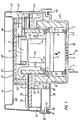
- a motor housing 3 is mounted on a carrier plate 1 with the aid of rubber sealing lips or foam strips 2.
- the motor housing 3 consists of a wide turbine part 3a and a narrower motor 36, on the top of which a radial fan 4 is arranged. This radial fan sucks in the cooling air in the direction of arrow 5, which is blown out at a blow-out opening 5a and in the direction of arrow 6 on the wall of an intermediate plate to be described later.
- the blower 7 also has a multi-stage turbine wheel with which the suction air is sucked in via the suction connection, not shown in detail via a suction hose, through a filter and flows in the direction of the arrow 8 via a suction opening 9 on the underside of the blower 7.
- This suction air is now soundproofed according to the invention, essentially the mass.
- an air grille 10 which has a mesh size of 3-8 mm and consists of square plastic rods, this grille showing the essential advantage that the suction air inflow drawn in in the direction of the arrow 8 is evened out. Above all, harmful eddies are avoided at the edges of the suction opening 9, which lead to corresponding whistling noises.
- the square ribs of this plastic grille are rounded on the intake side
- the blower 7 has radial Ausblasöffnun gene 11 through which the exhaust air flows in the direction of arrow 12 through a channel 13.
- the channel 13 is formed by an upwardly projecting flange 14 of the carrier plate 1, this channel wall being lined with a sound-absorbing mat 15. It is essential that the channel narrows in cross section 13a, so that the air flowing through it receives a substantial acceleration.
- the other side of the channel is formed by the wall 16 of a clamping plate 18, the air being deflected at an edge 17 to the front side of the clamping plate 18 lined with sound-absorbing mat 15.
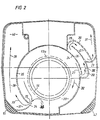
- the air flow is introduced into an annular channel 20 in the direction of arrow 19 (cf. FIG. 2).
- the ring channel 20 runs semicircularly around the housing. It is formed by two partial ring channels, which are approximately symmetrical to each other, as shown in Fig. 1 on the right side.
- the ring channels 20 are not exactly symmetrical to each other. They differ from each other in the radii.
- the ring channel on the left in FIG. 1 is described below with reference to FIG. 2. It can be seen that the air flows in the direction of arrow 21 into an outlet opening 22, which can also be seen in FIG. 1.
- This outlet opening 22 is partitioned off by a web 24 of the clamping plate 18, so that the air flows in the direction of arrow 25 through a channel 26, 27 designed as a chicane in the direction of arrow 28, is again deflected in the direction of arrow 29 on a web 30 of the clamping plate, and in the direction of the arrow 31 flows out of an exhaust air opening in the carrier plate and exits the housing there.
- the air can also flow further in the annular channel 20 in the direction of the arrow 32 and enter an opening 33 in a chamber 37 in the direction of the arrow 3b.
- the outlet opening 33 is formed by a rib 34 of the clamping plate and an adjacent rib 35.
- the chamber 37 leads into a further sound-damped channel 38, all the surfaces lying in the drawing plane in FIG. 2 being lined with foam mats.
- the air then flows in the direction of arrow 39 and then reaches a blow-out opening 40, which is arranged in a hood 41, on a very long path in the region of the channel 38.
- a triple-deflected baffle was therefore chosen on the right, upper side of FIG. 2 in order to obtain relatively the same silenced path as on the left-hand side with the channel 38, which only requires a single baffle, but a long, straight damped path.
- suction takes place via the suction opening 42 according to FIG. 2, which is located in FIG. 1 approximately in the area below this plate.
- the air passes through a relatively wide duct 44, which is lined with appropriate soundproofing mats, into a chamber 45, where it is deflected in the direction of arrow 43, and is fed via a radially extending duct 46 to the radial fan 4 of the drive motor.
- chamber 47 is also heavily damped with sound absorption mats, so that all air-contacting paths of the cooling air are lined with corresponding sound absorption mats.
- the radial fan 4 now draws in the cooling air, directs this cooling air via the motor windings in the direction of the arrow 48, which then enters a chamber 50 via a blow-out opening 49 (not shown) on the motor housing and there in the direction of the arrow 6 via an annular duct 51 and a wall 52 is deflected, which has a breakthrough that cannot be seen in FIG. 1. From there, the air enters an annular space 53 (arrow direction 54), which extends practically over 270 degrees of the housing, wherein in this annular space 53 electronic components of the device are advantageously arranged, which are acted upon by this cooling air and thereby be cooled.
- the electronic components consist, for example, of a triac for an automatic on / off switch with an associated suppressor choke and similar parts which generate a significant amount of waste heat and which are also cooled as a result.
- the air then flows out of the clamping plate via a housing opening 55 according to FIG. 2.
- This housing opening 55 lies below the horizontal part 56 of the carrier plate 1 and cannot be seen in FIG.
- the sound-absorbing mats preferably consist of a foam or a closed-cell foam rubber, a layer of bitumen mats 57 preferably being underlaid in order to ensure broadband noise damping.
- the housing hood 41 and the clamping plate 18 are made of injection-molded plastic parts, as is the bearing plate 56. It is also important in the present invention that a downwardly open channel 58 is arranged on the horizontal part 56 of the carrier plate 1 by a U-shaped one profiled seal 59 is arranged, in whose downwardly open U-profile the edge of the upwardly open vacuum cleaner container is inserted. As a result, further noise reduction is achieved and at the same time a seal and thus a simultaneous centering of the bearing plate 1 to the dirt suction container, i.e. no solid parts touch, vibration transmission is avoided.
- the soundproofing measures according to the invention are extremely inexpensive to manufacture because all parts consist of injection molded parts that only have corresponding soundproofing measures on the inside, i.e. sound absorption mats and bitumen mats must be lined.
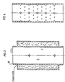
- Helmholtz - it is also possible, according to FIGS. 3 and 4, and according to FIGS. 5 and 6, to arrange either a silencer lined with mineral wool or an absorption damper or reflection damper (according to FIGS. 5 and 6) in the intake area of the engine, namely in the area of the air grille 10 and the suction opening 9.
- a plug-in collar is arranged flush with the outer edge of the suction opening 9, with which the silencers shown in FIGS. 3-6 with their associated collars 60, 61 are inserted.
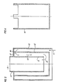
- FIG. 6 shows the inner part for the silencer according to FIG. 5.
- the inner part 62 is inserted axially into the part 63 according to FIG. 5, as is indicated in pencil in FIG. 5.
- the air is drawn in in the direction of arrow 65, deflected via the tabs 66 in the direction of arrow 67, guided downward in the direction of arrow 68 and in the direction of arrow 69 over the inner pot 70 of the muffler to the suction opening 9 of the carrier plate 1.
- a narrow copper conductor 71 In the area of the U-shaped sealing lip 59 there is a narrow copper conductor 71, the shape of which is adapted to the U-profile and which is seated on the metal edge of the vacuum cleaner container in an electrically conductive manner.
- This copper conductor is connected according to FIG. 1 via a conductor lug 72 and a connecting line 73 to the protective conductor of the mains voltage, so that the electrostatic charges arising on the vacuum cleaner container are discharged via this copper conductor 71 to the connection 73.
- the low-vibration fastening of the blower and the soft rubber rings effecting the blower motor must have a corresponding Shore hardness and dimension and at the same time be designed in such a way that the turbine is secured against twisting.
- the dimensions of the air gaps and air chambers must also be adjusted accordingly, essentially as shown in the drawing.
- the parameters channel width, channel height and channel length are important.
- the coordination of the sound absorption mats and the placement of the mats in the right place are also essential.
- the sucked-in and blown-out cooling air must also be guided, as explained above, in order to keep the sound pressure level as low as possible.
Landscapes
- Engineering & Computer Science (AREA)
- Mechanical Engineering (AREA)
- Exhaust Silencers (AREA)
- Motor Or Generator Cooling System (AREA)
- Electric Suction Cleaners (AREA)
- Soundproofing, Sound Blocking, And Sound Damping (AREA)
- Structures Of Non-Positive Displacement Pumps (AREA)
- Filters For Electric Vacuum Cleaners (AREA)
- Addition Polymer Or Copolymer, Post-Treatments, Or Chemical Modifications (AREA)
- Bridges Or Land Bridges (AREA)
- Golf Clubs (AREA)
- Prevention Of Fouling (AREA)
Description
- Die Erfindung betrifft einen Schmutzsauger mit einem Gehäuse und mit einem,im Gehäusedeckel angeordneten von einem Motor angetriebenen Gebläse nach dem Oberbegriff des Patentanspruchs 1.
- Ein derartiger Schmutzsauger ist bereits aus der DE-PS 556 550 bekannt. Dort sind im Auslaßweg Verengungen nach Art von radialen Zwischenstücken vorgesehen, die eine Drosselung bewirken, wobei zusätzlich die Abluft im Bereich von Umlenkblechen bogenförmig umgelenkt wird. Die Abluft wird hierdurch im Laufe des Abluftweges in verschiedenen Bereichen beschleunigt bzw. verzögert, ohne daß jedoch eine fühlbar verbesserte Schalldämmung eintritt, weil insbesondere im An- und Auslaufbereich des Motors des Schmutzsaugers ein charakteristisches Pfeifen auftritt.
- Ein weiterer Schmutzsauger ist aus der DE-A 3 023 630 bekannt. Der dort vorgesehene Auslaßweg ist spiralig und vergrößert sich in seinem Querschnitt stetig vom Einlaß zum Auslaß hin, ohne daß hierbei eine wesentliche Strömungslenkung gegeben ist. Es liegt hier also ein relativ langer Auslaßweg mit nur geringer Krümmung vor, bei dem weder Umlenkungen über scharfe Kanten gegeben sind, noch der im Auslaßweg strömende Luftstrom beschleunigt wird. Die Schalldämpfung dieses bekannten Schmutzsaugers dürfte der heutigen Anforderung nicht mehr genügen.
- Der Erfindung liegt daher die Aufgabe zugrunde, einen Schmutzsauger mit den eingangs genannten Merkmalen vorzuschlagen, der sich durch eine fühlbar verbesserte Schalldämmung auszeichnet.
- Zur Lösung der Aufgabe sind die Merkmale des kennzeichnenden Teils des Patentanspruchs 1 vorgesehen.
- Durch diese Merkmale wird die in die Auslasswege eintretende Luft abwechselnd mehrfach beschleunigt bzw. verlangsamt. Verbunden mit der erwähnten mehrfachen Umlenkung an den scharfen Kanten ergibt sich in überraschenderweise eine fühlbare und unerwartete Verringerung des Schallpegels. Versuche haben ergeben, dass der erfindungsgemässe Schmutzsauger einen Schallpegel von etwa 60 dB A hat. Diese Angabe ist naturgemäss von der jeweils getroffenen Dimensionierung des Schmutzsaugers insgesamt abhängig und daher in keiner Weise einschränkend zu verstehen.
- Vorteilhafte Ausgestaltungen der Erfindung sind durch die abhängigen Ansprüche definiert.
- Die Erfindung wird im folgenden anhand von Ausführungsbeispielen näher erläutert. Es zeigt:
- Fig. 1 einen Längsschnitt durch den oberen Teil eines Schmutzsaugers nach der Erfindung mit Gebläse, Gebläsemotor und schalldämpfenden Massnahmen;
- Fig. 2 eine Schnittansicht in Richtung des Pfeiles II von Figur 1;
- Fig. 3 in einem Längsschnitt einen mit Mineralwolle ausgekleideten Schalldämpfer,
- Fig. 4 einen Absorptionsdämpfer, ebenfalls im Längsschnitt;
- Fig. 5 einen Reflektionsdämpfer im Längsschnitt;
- Fig. 6 das Innenteil des Reflektionsdämpfers nach Fig. 5.
- Auf einer Trägerplatte 1 ist mit Hilfe von Gummidichtlippen oder Schaumstoffstreifen 2 ein Motorgehäuse 3 gelagert. Das Motorgehäuse 3 besteht aus einem breiten Turbinenteil 3a und einem schmaleren Motor 36 an dessen Oberseite ein Radial-Ventilator 4 angeordnet ist Dieser Radial-Ventilator saugt in Pfeilrichtung 5 die Kühlluft an, die an einer Ausblasöffnung 5a ausgeblasen wird und in Pfeilrichtung 6 an der Wandung einer noch später zu beschreibenden Zwischenplatte hochsteigt.
- Das Gebläse 7 besitzt ferner ein mehrstufiges Turbinonrad mit dem die Saugluft über den Sauganschluss nicht näher dargestellten Sauggehäuse über einen Saugschlauch über ein Filter angesaugt wird und in Pfeilrichtung 8 über eine Ansaugöffnung 9 an der Unterseite des Gebläses 7 einströmt. Diese Saugluft wird nun erfindungs-gemäss im wesentlichen Masse schallgedämpft.
- In der Ansaugöffnung 9 ist ein Luftgitter 10 vorhanden, das etwa eine Maschenweite von 3-8 mm aufweist und aus Vierkantkunststoffstäben besteht, wobei dieses Gitter den wesentlichen Vorteil zeigt, dass eine Vergleichmässigung des in Pfeilrichtung 8 eingesaugten Saugluftzustromes erfolgt. Es werden vor allem schädliche Wirbelbildungen an den Kanten der Ansaugöffnung 9 vermieden, die zu entsprechenden Pfeifgeräuschen führen. Die Vierkantrippen dieses Kunststoffgitters sind an der Ansaugseite entsprechend abgerundet
- Das Gebläse 7 weist radiale Ausblasöffnun gen 11 auf, durch die die Abluft in Pfeilrichtung 12 über einen Kanal 13 strömt. Der Kanal 13 wird durch einen nach oben ragenden Flansch 14 der Trägerplatte 1 gebildet, wobei diese Kanalwandung mit einer Schallschluck matte 15 ausgekleidet ist. Wesentlich ist, dass der Kanal sich im Querschnitt 13a verengt, so dass die hier hindurchströmende Luft eine wesentliche Beschleunigung erhält. Die andere Seite des Kanals wird durch die Wandung 16 einer Spannplatte 18 gebildet, wobei die Luft an einer Kante 17 an die mit Schallschluckmatte 15 ausgekleidete Stirnseite der Spannplatte 18 umgelenkt wird. Die Luftströmung wird in Pfeilrichtung 19 in einen Ringkanal 20 eingeleitet (vgl. Fig. 2).
- Der Ringkanal 20 läuft halbkreisförmig um das Gehäuse herum. Er wird von zwei Teil-Ringkanälen gebildet, die zueinander etwa symmetrisch sind, wie es in Fig. 1 auf der rechten Seite dargestellt ist.
- Die Ringkanäle 20 sind nicht genau zueinander symmetrisch. Sie weichen in den Radien voneinander ab. Im folgenden wird der Ringkanal links in Fig. 1 anhand von Fig. 2 beschrieben. Man sieht, dass die Luft in Pfeilrichtung 21 in eine Auslaß öffnung 22 einströmt, die auch in Fig. 1 zu sehen ist. Diese Auslaß Öffnung 22 wird durch einen Steg 24 der Spannplatte 18 abgeteilt, so dass die Luft in Pfeilrichtung 25 einen als Schikane ausgebildeten Kanal 26, 27 in Pfeilrichtung 28 durchströmt, in Pfeilrichtung 29 wiederum an einem Steg 30 der Spannplatte umgelenkt wird, und in Pfeilrichtung 31 aus einer Abluftöffnung in der Trägerplatte entströmt und dort aus dem Gehäuse austritt.
- Die Luft kann aber ebenso, anstatt in Pfeilrichtung 21 in die Öffnung 22 einzuströmen, in Pfeilrichtung 32 weiter im Ringkanal 20 entlangströmen und in Pfeilrichtung 3b über eine Auslaß öffnung 33 in einer Kammer 37 eintreten.
- Die Auslaß öffnung 33 ist durch eine Rippe 34 der Spannplatte und eine benachbarte Rippe 35 gebildet. Die Kammer 37 führt in einen weiteren schallgedämpften Kanal 38, wobei sämtliche in Fig. 2 in der Zeichenebene liegenden Flächen mit Schaumstoffmatten ausgekleidet sind. Die Luft strömt dann in Pfeilrichtung 39 weiter und gelangt dann auf einem sehr langen Weg im Bereich des Kanals 38 zu einer Ausblasöffnung 40, die in einer Haube 41 angeordnet ist.
- Auf der rechten, oberen Seite von Fig. 2 wurde eine dreifach umgelenkte Schikane deshalb gewählt, um relativ den gleichen schallgedämpften Weg zu gewinnen, wie auf der linken Seite mit der Kanel 38, die nur mit einer einzigen Umlenkschikane auskommt, dafür aber einen langen, geraden gedämpften Weg aufweist.
- Weiter wesentlich für den Erfolg der Schallschutzmassnahme ist, dass die Luft, die mit grossem Volumen in den Ringkanal 20 eintritt, zunächst an den Umlenkschikanen sehr stark beschleunigtwird, um dann in danach geschalteten Ausdehnungsräumen wieder verlangsamt zu werden. Hierdurch gelingt es, eine breitbandige Schalldämpfung zu erreichen, nachdem sämtliche Deckflächen, die in Fig. 2 in der Zeichenebene liegen, mit Schallschutzmatten ausgekleidet sind.
- Im folgenden wird die Schalldämpfung der Motorkühlluft anhand von Fig. 1 erläutert.
- In Fig. 1 wird über die Ansaugöffnung 42 gemäss Fig. 2 angesaugt, die sich in Fig.1 etwa im Bereich unterhalb dieser Platte befindet. Die Luft gelangt über einen relativ breiten Kanal 44, der mit entsprechenden Schallschutzmatten ausgekleidet ist, in eine Kammer 45, wo sie in Pfeilrichtung 43 umgelenkt wird, und über einen radial sich erstreckenden Kanal 46 zum Radial-Ventilator 4 des Antriebsmotors zugeführt wird. Wichtig ist hierbei, dass auch die Kammer 47 sehr stark mit Schallschluckmatten bedämpft ist, so dass sämtliche luftberührten Wege der Kühlluft mit entsprechenden Schallschluckmatten ausgekleidet sind. Der Radial-Ventilator 4 saugt nun die Kühlluft an, leitet diese Kühlluft über die Motorwicklungen in Pfeilrichtung 48, die dann über eine nicht näher dargestellte Ausblasöffnung 49 am Motorgehäuse in eine Kammer 50 eintritt und dort in Pfeilrichtung 6 über einen Ringkanal 51 und eine Wand 52 umgelenkt wird, die einen Durchbruch aufweist, der in Fig. 1 nicht zu entnehmen ist. Von dort gelangt die Luft in einen Ringraum 53 hinein (Pfeilrichtung 54), der sich praktisch über 270 Grad des Gehäuses erstreckt, wobei in diesen Ringraum 53 in vorteilhafter Weise noch Elektronik-Komponenten des Geräts angeordnet sind, die von dieser Kühlluft mit beaufschlagt und dadurch gekühlt werden. Die Elektronik-Komponenten bestehen beispielsweise aus einem Triak für eine Ein-Ausschalt-Automatik mit einer zugeordneten Entstördrossel und ähnlichen Teilen, die eine wesentliche Abwärme erzeugen und die hierdurch auch gekühlt werden. Die Luft entströmt dann über eine Gehäuseöffnung 55 gemäss Fig. 2 aus der Spannplatte heraus.
- Diese Gehäuseöffnung 55 iiegt unterhalb des horizontalen Teils 56 der Trägerplatte 1 und ist in Fig.1 nicht zu erkennen.
- Wesentlich ist auch hier, dass bei der Motorkühlluft sämtliche luftberührten Räume schallgedämpft sind, und die Luft mehrfach über Schikanen umgelenkt wird, so dass hier auch eine wesentliche Geräuschdämpfung der Motorkühlluft erfolgt.
- Die Schallschluckmatten bestehen vorzugsweise aus einem Schaumstoff oder aus einem geschlossenporigen Moosgummi, wobei bevorzugt noch eine Schicht von Bitumenmatten 57 unterlegt ist, um eine breitbandige Geräuschdämpfung zu gewährleisten.
- Die Gehäusehaube 41 und die Spannplatte 18 bestehen aus Kunststoff-Spritzgussteilen, ebenso die Lagerplatte 56. Wesentlich bei der vorliegenden Erfindung ist auch, dass am horizontalen Teil 56 der Trägerplatte 1 ein nach unten geöffneter Kanal 58 radial umlaufend angeordnet ist, indem eine U-förmige profilierte Dichtung 59 angeordnet ist, in deren nach unten offenem U-Profil der Rand des nach oben offenen Schmutzsaugerbehälters eingesetzt wird. Hierdurch wird eine weitere Geräuschdämpfung erzielt und gleichzeitig eine Abdichtung und damit eine gleichzeitige Zentrierung von Lagerplatte 1 zu dem Schmutzsaugerbehälter, d.h. es berühren sich keine festen Teile, eine Schwingungsübertragung wird vermieden.
- Die Schalldämpfungsmassnahmen nach der Erfindung sind ausserordentlich kostengünstig herzustellen, weil sämtliche Teile aus Spritzgussteilen bestehen, die nur innen mit entsprechenden Schallschutzmassnahmen, d.h. also Schallschluckmatten und Bitumenmatten ausgekleidet werden müssen.
- Es ist möglich, zusätzlich Helmholtz-Resonatoren zu verwenden; ebenso ist es möglich, gemäss Fig. 3 und Fig. 4, sowie gemäss Fig. 5 und Fig. 6, entweder einen mit Mineralwolle ausgekleideten Schalldämpfer oder einen Absorptionsdämpfer bzw. Reflektionsdämpfer (gemäss Fig. 5 und 6) im Ansaugbereich des Motors anzuordnen, nämlich im Bereich des Luftgitters 10 und der Ansaugöffnung 9. In diesem Fall ist bündig mit dem Aussenrand der Ansaugöffnung 9 ein Steckkragen angeordnet, mit dem die in den Fig. 3-6 gezeigten Schalldämpfer mit ihren zugeordneten Kragen 60, 61 eingesteckt werden.
- Fig. 6 zeigt das Innenteil für den Schalldämpfer nach Fig. 5. Das Innenteil 62 wird axial in das Teil 63 nach Fig. 5 eingesteckt, so wie es in Fig. 5 mit Bleistift angedeutet ist. Die Luft wird in Pfeilrichtung 65 angesaugt, über die Laschen 66 in Pfeilrichtung 67 umgelenkt, in Pfeilrichtung 68 nach unten geführt und in Pfeilrichtung 69 über den inneren Topf 70 des Schalldämpfers zur Ansaugöffnung 9 der Träger platte 1 geführt.
- Ähnliche Verhältnisse bestehen auch bei der Fig. 3, wo ein bedämpfter Schalldämpfer verwendet wird. Ebenso ist es möglich, auf der Motor-kühlluftseite einen bedämpften Helmholtz-Resonator einzubauren, der bevorzugt im Bereich der Kammer 45 angeordnet ist, der nicht selbst von Luft durchströmt ist, sondern der als Hohlkörper an seinen Aussenwandungen in das inneführende Bohrungen genau festgelegten Durchmessers und Abstandes aufweist, so dass die angesaugte Kühlluft mit der Oberfläche hinweggeführt wird und über den Bohrungsrand dieser Bohrungen strömt und hierdurch ebenfalls ein Dämpfungseffekt erzielt wird.
- Im Bereich der U-profilierten Dichtlippe 59 ein schmaler Kupferleiter 71 angeordnet ist, der in seiner Formgebung dem U-profil angepasst ist und der elektrisch leitfähig auf dem Metallrand des Schmutzsaugerbehälters aufsitzt. Dieser Kupferleiter ist gemäss Fig. 1 über eine Leiterfahne 72 und eine Anschluss leitung 73 mit dem Schutzleiter der netzspannung verbunden, so dass die am Schmutzsaugerbehälter entstehenden, elecktrostatischen Aufladungen über diesen Kupferleiter 71 an die Anscheuß 73 abgeleitet werden.
- Die schwingungsarme Befestigung des Gebläses und des Gebläsemotors bewirkenden Weichgummiringe müssen eine entsprechende Shore-Härte und Abmessung haben und gleichzeitig so ausgeführt sein, dass die Turbine gegen ein Verdrehen gesichert ist. Die Luftstrecken und Luftkammern müssen in ihren Dimensionierungen ebenfalls entsprechend abgestimmt werden, im wesentlichen wie zeichnerisch dargestellt. Wichtig sind die Parameter Kanalbreite, Kanalhöhe und Kanallänge. Auch die Abstimmung der Schallschluckmatten sowie die Einbringung der Matten an der richtigen Stelle sind wesentlich. Die angesaugte und ausgeblasene Kühlluft muss ebenfalls, wie vorstehend erläutert, geführt werden, um auch hier den Schalldruckpegel möglichst gering zu halten.
Claims (9)
Priority Applications (1)
| Application Number | Priority Date | Filing Date | Title |
|---|---|---|---|
| AT83105740T ATE29654T1 (de) | 1982-07-06 | 1983-06-11 | Schmutzsauger. |
Applications Claiming Priority (2)
| Application Number | Priority Date | Filing Date | Title |
|---|---|---|---|
| DE3225258A DE3225258C2 (de) | 1982-07-06 | 1982-07-06 | Schmutzsauger |
| DE3225258 | 1982-07-06 |
Publications (3)
| Publication Number | Publication Date |
|---|---|
| EP0099466A1 EP0099466A1 (de) | 1984-02-01 |
| EP0099466B1 EP0099466B1 (de) | 1987-09-16 |
| EP0099466B2 true EP0099466B2 (de) | 1991-12-18 |
Family
ID=6167758
Family Applications (1)
| Application Number | Title | Priority Date | Filing Date |
|---|---|---|---|
| EP83105740A Expired - Lifetime EP0099466B2 (de) | 1982-07-06 | 1983-06-11 | Schmutzsauger |
Country Status (5)
| Country | Link |
|---|---|
| US (1) | US4665581A (de) |
| EP (1) | EP0099466B2 (de) |
| AT (1) | ATE29654T1 (de) |
| DE (2) | DE3225258C2 (de) |
| ZA (1) | ZA834398B (de) |
Cited By (1)
| Publication number | Priority date | Publication date | Assignee | Title |
|---|---|---|---|---|
| DE102004005500A1 (de) * | 2004-01-30 | 2005-08-18 | Alfred Kärcher Gmbh & Co. Kg | Staubsauger |
Families Citing this family (52)
| Publication number | Priority date | Publication date | Assignee | Title |
|---|---|---|---|---|
| GB8703295D0 (en) * | 1987-02-13 | 1987-03-18 | Smith A G | Vacuum cleaner system |
| JPH0665332B2 (ja) * | 1987-05-06 | 1994-08-24 | 株式会社日立製作所 | 電気掃除機 |
| JPH01305916A (ja) * | 1988-06-06 | 1989-12-11 | Hitachi Ltd | 電気掃除機 |
| DE3904392A1 (de) * | 1989-02-14 | 1990-08-16 | Mauz & Pfeiffer Progress | Staubsauger |
| DE3928313A1 (de) * | 1989-08-26 | 1991-02-28 | Wap Reinigungssysteme | Schmutzsauger |
| US4997342A (en) * | 1989-11-13 | 1991-03-05 | Conger William W Iv | Air blower with flexible housing |
| US5143524A (en) * | 1990-02-20 | 1992-09-01 | The Scott Fetzer Company | Electrostatic particle filtration |
| US5376168A (en) * | 1990-02-20 | 1994-12-27 | The L. D. Kichler Co. | Electrostatic particle filtration |
| US5405434A (en) * | 1990-02-20 | 1995-04-11 | The Scott Fetzer Company | Electrostatic particle filtration |
| US4970753A (en) * | 1990-02-23 | 1990-11-20 | Ryobi Motor Products Corp. | Vacuum cleaner noise reducing arrangement |
| JP3047984B2 (ja) * | 1990-04-18 | 2000-06-05 | 株式会社日立製作所 | 電気掃除機 |
| US5067584A (en) * | 1990-04-25 | 1991-11-26 | Williams William H | Low cost replaceable type sound dampening unit for vacuum cleaning machine |
| KR930001867A (ko) * | 1991-07-26 | 1993-02-22 | 배순훈 | 저소음 진공청소기 |
| KR940000714B1 (ko) * | 1991-11-25 | 1994-01-28 | 삼성전자 주식회사 | 전기 소제기 |
| US5353469A (en) * | 1992-07-01 | 1994-10-11 | National Super Service Company | Wet/dry vacuum cleaner with noise reducing housing structure |
| US5400463A (en) * | 1993-02-16 | 1995-03-28 | Beam Of Canada, Inc. | Noise dampened canister vacuum cleaner |
| US5513417A (en) * | 1993-07-19 | 1996-05-07 | Samsung Electronics Co., Ltd. | Silencing device for vacuum cleaner |
| US5526805A (en) * | 1993-11-03 | 1996-06-18 | Dryden Engineering Company, Inc. | In-line silencer for clean room breathing apparatus |
| DE4408278A1 (de) * | 1994-03-11 | 1995-09-14 | Gaggenau Werke | Dunstabzugshaube mit wenigstens teilweiser Auslöschung des Lüftergeräusches |
| KR970009718A (ko) * | 1995-08-31 | 1997-03-27 | 배순훈 | 진공 청소기의 배기 유로를 길게한 흡음방 |
| US5765257A (en) * | 1996-08-01 | 1998-06-16 | Emerson Electric Co. | Muffler |
| DE19741545A1 (de) * | 1997-09-20 | 1999-03-25 | Proair Geraetebau Gmbh | Naßreinigungsgerät |
| US6003200A (en) * | 1997-11-14 | 1999-12-21 | Overhead Door Corporation | Powerhead housing assembly for vacuum cleaner |
| US5979013A (en) * | 1998-03-10 | 1999-11-09 | The Toro Company | Portable blower with noise reduction |
| US6158082A (en) | 1998-03-10 | 2000-12-12 | The Toro Company | Portable blower with blower tube noise reduction |
| US6219880B1 (en) | 1998-09-17 | 2001-04-24 | Pullman-Holt Corporation | Vacuum cleaner |
| AU2001242317B2 (en) * | 2000-03-24 | 2004-11-11 | Nilfisk-Advance A/S | A silencer for an air flow generator |
| EP1172059A1 (de) * | 2000-07-14 | 2002-01-16 | Nilfisk Advance A/S | Staubsauger mit Schalldämmungsmittel |
| US6499183B1 (en) * | 2000-09-29 | 2002-12-31 | Oreck Holdings, Llc | Low-profile and highly-maneuverable vacuum cleaner having a headlight, a sidelight, anti-ingestion bars, side brushes, a squeegee, and a scent cartridge |
| CA2332195A1 (en) | 2001-01-24 | 2002-07-24 | Alexandre Plomteux | Quiet central vacuum power unit |
| US6807709B2 (en) * | 2002-02-07 | 2004-10-26 | Koblenz Electrica, S.A. De C.V. | Vacuum cleaner cooling system |
| DE10247550A1 (de) * | 2002-10-11 | 2004-04-22 | Werner, Jürgen | Radialgebläse für Laub- und Abfallsauger, Laubbläser oder Laubladegeräte |
| KR100555205B1 (ko) * | 2003-12-31 | 2006-03-03 | 삼성광주전자 주식회사 | 진공청소기 |
| US7461430B2 (en) * | 2005-01-10 | 2008-12-09 | Broan-Nutone Llc | Vacuum system and method |
| US20080016646A1 (en) * | 2005-01-10 | 2008-01-24 | Martin Gagnon | Housing assembly for a vacuum |
| USD534697S1 (en) | 2005-01-10 | 2007-01-02 | Broan-Nutone Llc | Vacuum system |
| US7406744B2 (en) * | 2005-01-20 | 2008-08-05 | Marc Bruneau | Central vacuum system with secondary airflow path |
| CA2545977A1 (en) * | 2005-05-09 | 2006-11-09 | Emerson Electric Co. | Noise-reduced vacuum appliance |
| US7690077B2 (en) * | 2005-09-28 | 2010-04-06 | Electrolux Home Care Products, Ltd. | Central vacuum units with an acoustic damping pathway |
| US20070174992A1 (en) * | 2005-09-30 | 2007-08-02 | Murray Christopher W | Quiet vacuum cleaner |
| KR101212291B1 (ko) * | 2005-12-30 | 2012-12-12 | 삼성전자주식회사 | 진공청소기 |
| DE102006058840B4 (de) * | 2006-12-13 | 2021-01-14 | Pfeiffer Vacuum Gmbh | Vakuumpumpe |
| DE102008046941A1 (de) * | 2008-09-08 | 2010-03-11 | Alfred Kärcher Gmbh & Co. Kg | Staubsauger |
| DE102010040669A1 (de) * | 2010-09-13 | 2012-03-15 | Alfred Kärcher Gmbh & Co. Kg | Saugreinigungsvorrichtung |
| JP5728338B2 (ja) * | 2011-09-07 | 2015-06-03 | 株式会社マキタ | 電動工具用集塵装置及び電動工具 |
| US20130133155A1 (en) * | 2011-11-28 | 2013-05-30 | Julio C. Perez | Vacuum cleaner incorporating noise suppression system |
| WO2014005586A1 (en) * | 2012-07-04 | 2014-01-09 | Nilfisk-Advance A/S | A silencer system for a vacuum motor in a suction cleaner |
| JP5903544B2 (ja) * | 2012-09-25 | 2016-04-13 | パナソニックIpマネジメント株式会社 | 電気掃除機 |
| EP3207846B1 (de) * | 2016-02-19 | 2019-01-09 | Nilfisk A/S | Motorgehäuse mit schalldämpfer für eine staubsaugvorrichtung |
| DK3238592T3 (da) | 2016-04-27 | 2021-07-19 | Diversey Inc | Støvsuger |
| US11560904B2 (en) * | 2018-09-25 | 2023-01-24 | Abb Schweiz Ag | Modular low-noise motor |
| EP4129134B1 (de) * | 2021-08-03 | 2025-05-14 | Vorwerk & Co. Interholding GmbH | Haushaltsgerät mit einer schalldämpfungseinrichtung |
Family Cites Families (11)
| Publication number | Priority date | Publication date | Assignee | Title |
|---|---|---|---|---|
| DE7126226U (de) * | 1971-12-16 | Siemens Gmbh | Gebläselagerung in Staubsaugern oder ähnlichen Geräten | |
| DE7238517U (de) * | 1973-01-18 | Chemische Werke Worms Gmbh | Staubsauger | |
| US1565932A (en) * | 1921-05-24 | 1925-12-15 | Motor Player Corp | Means for actuating player pianos |
| DE556550C (de) * | 1929-09-03 | 1932-08-10 | Siemens Schuckertwerke Akt Ges | Einrichtung zur Verminderung des Geraeusches von Geblaesen, insbesondere fuer elektrisch angetriebene Staubsauger |
| US2884185A (en) * | 1956-06-29 | 1959-04-28 | American Lincoln Corp | Suction tank head |
| DE1628835A1 (de) * | 1966-04-02 | 1971-06-16 | Altenburg Elektrowaerme | Einrichtung zur Geraeuschminderung an elektromotorisch angetriebenen Geraeten |
| DE2615507A1 (de) * | 1976-04-09 | 1977-10-20 | Mauz & Pfeiffer Progress | Staubsauger, insbesondere elektrisch betriebener haushaltstaubsauger |
| CA1082407A (en) * | 1977-05-13 | 1980-07-29 | Alan J. Brazier | Apparatus for cleaning floors, carpets and the like |
| US4195969A (en) * | 1978-01-05 | 1980-04-01 | Clarke-Gravely Corporation | Vacuum cleaner |
| US4330899A (en) * | 1980-04-18 | 1982-05-25 | Shop-Vac Corporation | Noise reducing blower motor housing means for vacuum cleaner, or the like |
| US4435877A (en) * | 1982-09-30 | 1984-03-13 | Shop-Vac Corporation | Noise reducing means for vacuum cleaner |
-
1982
- 1982-07-06 DE DE3225258A patent/DE3225258C2/de not_active Expired
-
1983
- 1983-06-11 EP EP83105740A patent/EP0099466B2/de not_active Expired - Lifetime
- 1983-06-11 AT AT83105740T patent/ATE29654T1/de not_active IP Right Cessation
- 1983-06-11 DE DE8383105740T patent/DE3373618D1/de not_active Expired
- 1983-06-15 ZA ZA834398A patent/ZA834398B/xx unknown
-
1986
- 1986-01-08 US US06/816,967 patent/US4665581A/en not_active Expired - Lifetime
Cited By (1)
| Publication number | Priority date | Publication date | Assignee | Title |
|---|---|---|---|---|
| DE102004005500A1 (de) * | 2004-01-30 | 2005-08-18 | Alfred Kärcher Gmbh & Co. Kg | Staubsauger |
Also Published As
| Publication number | Publication date |
|---|---|
| DE3225258C2 (de) | 1985-11-28 |
| DE3373618D1 (en) | 1987-10-22 |
| ATE29654T1 (de) | 1987-10-15 |
| US4665581A (en) | 1987-05-19 |
| ZA834398B (en) | 1984-03-28 |
| EP0099466A1 (de) | 1984-02-01 |
| EP0099466B1 (de) | 1987-09-16 |
| DE3225258A1 (de) | 1984-01-12 |
Similar Documents
| Publication | Publication Date | Title |
|---|---|---|
| EP0099466B2 (de) | Schmutzsauger | |
| EP2267373B1 (de) | Externes Gebläse für Dunstabzugsvorrichtung | |
| EP0791135B1 (de) | Schalldämpfer | |
| DE60011339T2 (de) | Motorkühlung und schalldämmendes System | |
| DE69605796T2 (de) | Abzugssystem für küchen | |
| DE19802111B4 (de) | Zentrifugalgebläse mit einer Vielzahl von Nebenschaufeln | |
| DE3402603A1 (de) | Staubsauger | |
| DE10160465C2 (de) | Elektrogerät mit Schalldämpfer | |
| DE69713561T2 (de) | Küchenventilator | |
| DE19846666C2 (de) | Schalldämpfende Leitung | |
| DE3120569A1 (de) | "kuechendunstabzugshaube" | |
| DE2362013A1 (de) | Wirbelluftreinigeranordnung mit einer schalldaempfungseinrichtung | |
| DE3027701A1 (de) | Staubsauger | |
| EP1656061B1 (de) | Staubsauger mit abluftströmungskanälen | |
| EP3499046B1 (de) | Verfahren zur herstellung eines gebläsegehäuses | |
| DE4326837A1 (de) | Absaugvorrichtung | |
| DE102017210758A1 (de) | Gebläse | |
| EP0392453B1 (de) | Fliehkraftabscheider | |
| DE102023115294B4 (de) | Gebläse für einen Staubsauger | |
| DE2854860C2 (de) | Elektroquirl | |
| BE1030803B1 (de) | In ein Kochfeld baulich integrierbare Dunstabzugsvorrichtung und Kochfeld | |
| EP0542178B1 (de) | Schalldämpfung der von einem Verdichter angesaugten Luft | |
| DE2543530B1 (de) | Axialkuehlluftgeblaese mit einem leitrad fuer eine luftgekuehlte brennkraftmaschine | |
| EP1217308B1 (de) | Dunstabzugshaube | |
| DE2917094B1 (de) | Vorrichtung zur Schalldaemmung in einem Staubsauger |
Legal Events
| Date | Code | Title | Description |
|---|---|---|---|
| PUAI | Public reference made under article 153(3) epc to a published international application that has entered the european phase |
Free format text: ORIGINAL CODE: 0009012 |
|
| AK | Designated contracting states |
Designated state(s): AT BE CH DE FR GB IT LI LU NL SE |
|
| 17P | Request for examination filed |
Effective date: 19840514 |
|
| RAP1 | Party data changed (applicant data changed or rights of an application transferred) |
Owner name: WAP REINIGUNGSSYSTEME GMBH & CO. |
|
| GRAA | (expected) grant |
Free format text: ORIGINAL CODE: 0009210 |
|
| AK | Designated contracting states |
Kind code of ref document: B1 Designated state(s): AT BE CH DE FR GB IT LI LU NL SE |
|
| PG25 | Lapsed in a contracting state [announced via postgrant information from national office to epo] |
Ref country code: NL Effective date: 19870916 Ref country code: BE Effective date: 19870916 |
|
| REF | Corresponds to: |
Ref document number: 29654 Country of ref document: AT Date of ref document: 19871015 Kind code of ref document: T |
|
| REF | Corresponds to: |
Ref document number: 3373618 Country of ref document: DE Date of ref document: 19871022 |
|
| ITF | It: translation for a ep patent filed | ||
| GBT | Gb: translation of ep patent filed (gb section 77(6)(a)/1977) | ||
| ET | Fr: translation filed | ||
| NLV1 | Nl: lapsed or annulled due to failure to fulfill the requirements of art. 29p and 29m of the patents act | ||
| PG25 | Lapsed in a contracting state [announced via postgrant information from national office to epo] |
Ref country code: AT Effective date: 19880611 |
|
| PLBI | Opposition filed |
Free format text: ORIGINAL CODE: 0009260 |
|
| PG25 | Lapsed in a contracting state [announced via postgrant information from national office to epo] |
Ref country code: LU Free format text: LAPSE BECAUSE OF NON-PAYMENT OF DUE FEES Effective date: 19880630 Ref country code: LI Effective date: 19880630 Ref country code: CH Effective date: 19880630 |
|
| 26 | Opposition filed |
Opponent name: SIEMENS AKTIENGESELLSCHAFT, BERLIN UND MUENCHEN Effective date: 19880614 Opponent name: DUEPRO AG Effective date: 19880615 |
|
| REG | Reference to a national code |
Ref country code: CH Ref legal event code: PL |
|
| PUAH | Patent maintained in amended form |
Free format text: ORIGINAL CODE: 0009272 |
|
| STAA | Information on the status of an ep patent application or granted ep patent |
Free format text: STATUS: PATENT MAINTAINED AS AMENDED |
|
| 27A | Patent maintained in amended form |
Effective date: 19911218 |
|
| AK | Designated contracting states |
Kind code of ref document: B2 Designated state(s): AT BE CH DE FR GB IT LI LU NL SE |
|
| ITF | It: translation for a ep patent filed | ||
| ET3 | Fr: translation filed ** decision concerning opposition | ||
| GBTA | Gb: translation of amended ep patent filed (gb section 77(6)(b)/1977) | ||
| ITTA | It: last paid annual fee | ||
| EAL | Se: european patent in force in sweden |
Ref document number: 83105740.1 |
|
| PGFP | Annual fee paid to national office [announced via postgrant information from national office to epo] |
Ref country code: GB Payment date: 20000511 Year of fee payment: 18 |
|
| PGFP | Annual fee paid to national office [announced via postgrant information from national office to epo] |
Ref country code: SE Payment date: 20000628 Year of fee payment: 18 Ref country code: FR Payment date: 20000628 Year of fee payment: 18 |
|
| PGFP | Annual fee paid to national office [announced via postgrant information from national office to epo] |
Ref country code: DE Payment date: 20010516 Year of fee payment: 19 |
|
| PG25 | Lapsed in a contracting state [announced via postgrant information from national office to epo] |
Ref country code: GB Free format text: LAPSE BECAUSE OF NON-PAYMENT OF DUE FEES Effective date: 20010611 |
|
| PG25 | Lapsed in a contracting state [announced via postgrant information from national office to epo] |
Ref country code: SE Free format text: LAPSE BECAUSE OF NON-PAYMENT OF DUE FEES Effective date: 20010612 |
|
| GBPC | Gb: european patent ceased through non-payment of renewal fee |
Effective date: 20010611 |
|
| EUG | Se: european patent has lapsed |
Ref document number: 83105740.1 |
|
| PG25 | Lapsed in a contracting state [announced via postgrant information from national office to epo] |
Ref country code: FR Free format text: LAPSE BECAUSE OF NON-PAYMENT OF DUE FEES Effective date: 20020228 |
|
| PG25 | Lapsed in a contracting state [announced via postgrant information from national office to epo] |
Ref country code: DE Free format text: LAPSE BECAUSE OF NON-PAYMENT OF DUE FEES Effective date: 20030101 |