EP0099076B1 - Bogenstranggiessanlage mit bogenförmigem, starrem Anfahrstrang und Verfahren zum Betrieb einer solchen Anlage - Google Patents
Bogenstranggiessanlage mit bogenförmigem, starrem Anfahrstrang und Verfahren zum Betrieb einer solchen Anlage Download PDFInfo
- Publication number
- EP0099076B1 EP0099076B1 EP83106665A EP83106665A EP0099076B1 EP 0099076 B1 EP0099076 B1 EP 0099076B1 EP 83106665 A EP83106665 A EP 83106665A EP 83106665 A EP83106665 A EP 83106665A EP 0099076 B1 EP0099076 B1 EP 0099076B1
- Authority
- EP
- European Patent Office
- Prior art keywords
- starting
- head
- arc
- strand
- curved
- Prior art date
- Legal status (The legal status is an assumption and is not a legal conclusion. Google has not performed a legal analysis and makes no representation as to the accuracy of the status listed.)
- Expired
Links
- 238000009749 continuous casting Methods 0.000 title claims abstract description 11
- 238000000034 method Methods 0.000 title claims description 9
- 230000008878 coupling Effects 0.000 claims abstract description 22
- 238000010168 coupling process Methods 0.000 claims abstract description 22
- 238000005859 coupling reaction Methods 0.000 claims abstract description 22
- 238000005266 casting Methods 0.000 claims abstract description 12
- 230000000717 retained effect Effects 0.000 claims 1
- 238000009434 installation Methods 0.000 abstract 1
- 229910000831 Steel Inorganic materials 0.000 description 3
- 238000005452 bending Methods 0.000 description 3
- 239000010959 steel Substances 0.000 description 3
- 238000001816 cooling Methods 0.000 description 2
- 238000003780 insertion Methods 0.000 description 2
- 230000037431 insertion Effects 0.000 description 2
- 238000000926 separation method Methods 0.000 description 2
- 230000002730 additional effect Effects 0.000 description 1
- 238000010276 construction Methods 0.000 description 1
- 230000003247 decreasing effect Effects 0.000 description 1
- 230000007257 malfunction Effects 0.000 description 1
- 239000002184 metal Substances 0.000 description 1
- 238000003825 pressing Methods 0.000 description 1
- 239000007921 spray Substances 0.000 description 1
- 239000007858 starting material Substances 0.000 description 1
Images
Classifications
-
- B—PERFORMING OPERATIONS; TRANSPORTING
- B22—CASTING; POWDER METALLURGY
- B22D—CASTING OF METALS; CASTING OF OTHER SUBSTANCES BY THE SAME PROCESSES OR DEVICES
- B22D11/00—Continuous casting of metals, i.e. casting in indefinite lengths
- B22D11/08—Accessories for starting the casting procedure
- B22D11/081—Starter bars
- B22D11/083—Starter bar head; Means for connecting or detaching starter bars and ingots
Definitions
- the invention relates to a continuous sheet caster with an arcuate, rigid start-up strand, wherein in the area of the straightening machine a roll that can be adjusted towards the strand path separates the cast strand from the start-up strand while maintaining the position of the longitudinal axis of the moving rigid start-up strand and a method for operating such a system.
- a start-up line is required to start up a continuous caster.
- the head of the start-up strand which is provided with a coupling part, closes the mold on its underside and creates a connection with the cast strand at the start of casting so that it can be pulled out of the mold and inserted into the driver.
- the start-up strand can be composed, for example, of individual links or constructed from other flexible constructions, or can consist of a rigid, arc-shaped piece of steel, which is generally approximately the length of a quarter circle.
- the starting strand moving along its longitudinal axis remains on its path of motion.
- the start-up head connected to the cast strand runs through the shears and is only separated from the end of the shear after the cropping cut and is reused.
- a new screw must be inserted in the cold strand head as a coupling element for the subsequent casting.
- This continuous caster has several disadvantages.
- the start-up head remaining at the end of the crimp which must be manually separated after each casting, provided with a new coupling part before each reuse, coupled to the start-up line and secured against falling out, causes additional costs.
- the top end cannot be properly aligned. be tet, because the strand does not lie on the straight roller bed during the time of the pressing process. Inaccurately directed top ends on the cast strand often cause disturbances when entering a subsequent pair of shears.
- a continuous sheet caster which describes a start-up line which consists of a rigid and a flexible part composed of links.
- the rigid and the flexible part each have a length of approximately half the circular strand guide.
- the start-up head of this start-up line is provided with a permanent coupling part, the uncoupling being effected by a relative movement between the cast strand and the start-up head transversely to the longitudinal axis of the line.
- this starting strand is only about half rigid, it fulfills two essential requirements of the rigid starting strand group.
- the uncoupling between the cast strand and the start-up strand is carried out on the non-directional warm strand and the rigid part of the start-up strand bridges larger sections of the secondary cooling zone below the mold that are not guided by the strand.
- This start-up strand which is rigid over half its length, is therefore to be assigned to the group of rigid start-up lines in terms of its function. Even with such systems, the top end of the cast strand cannot be properly directed during the uncoupling time. Depending on the force required to separate the cast coupling part from the start-up head, the start-up strand can suffer permanent deformation, which can cause difficulties when re-inserting the start-up strand into the mold.
- the invention is based on the object of using a rigid start-up line with a permanent coupling device in a continuous casting machine, which on the one hand ensures trouble-free decoupling between the permanent coupling part and the cast line, prevents bending of the rigid start-up line during decoupling, even at high casting speeds and at large casting speed changes of the strand caused by non-controllable spouts on the tundish, the uncoupling of the cast strand from Anfahrkopt does not cause any malfunctions and a perfect straightening of the head of the cast strand guarantees precise introduction into a subsequent pair of scissors.
- a start-up head provided with a permanent coupling part which can be released by pivoting movement is pivoted on the start-up line about an axis arranged transversely to the direction of the line run, and the employable roller exerts the force for decoupling the permanent clutch device on the pivotable start-up head in such a way that the latter starts up during the casting operation from its axial position pivoted away from the arcuate longitudinal axis of the starting strand.
- the process for operating this continuous sheet caster is characterized in that the contact force of the adjustable roller for decoupling is applied to a start-up head part which can be pivoted outward from the curved line with a permanent coupling and is released from the cast strand by pivoting the start-up head and that the decoupled start-up head is pivoted back in the direction of the longitudinal axis of the start-up line during the further movement of the start-up line.
- the arrangement according to the invention further reduces the bending forces acting on the rigid starting strand by the pivoting movement of the starting head when uncoupling, which serves to maintain its precise shape and increases the resulting accuracy of insertion into the mold. Furthermore, the distances covered during the decoupling process, which are caused by different casting speeds, can be eliminated as a disturbing factor within wide limits.
- the straightening process can also begin before the adjustable roller presses on the cast strand. When the hot strand reaches the positionable roll, the uncoupling has taken place and the roll only has the function of a straightening roll.
- the swiveling start-up head also facilitates insertion into the mold if, after a long period of operation, the guide precision for the start-up strand on the drive rollers has decreased due to natural wear and tear.
- the swiveling start-up head can also be inserted into the mold without problems under such circumstances.
- the swiveling start-up head can be swiveled back manually into the starting position and secured in the starting position with a shear bolt that can be sheared off by small forces.
- the starting head be assigned a device for automatic pivoting back into a position in alignment with the curved longitudinal axis of the rigid starting line.
- a device for the automatic pivoting back of the tilted head can consist, for example, of a counterweight attached to the head.
- Another advantageous device for the automatic pivoting back of the tilted start-up head can also consist of a deflection roller arranged at the cold-strand cassette entrance and a resilient snap-in element between the start-up head and the start-up strand. Both solutions ensure an axial positioning of the swiveling start-up head as the start-up line enters the strand guide and the mold.
- the specified time for the release process between the cast strand and the start-up head by the adjustable roller can be influenced by the choice of the length of the start-up head part that can be pivoted outwards. It is therefore particularly advantageous if the start-up head part, which can be pivoted outwards from the curved line, is at least 300 mm long.
- the starting head In the case of continuous casting plants, the lateral guidance of which for the rigid starting strand has become imprecise, for example due to wear, it can be advantageous if the starting head is arranged such that it can be moved about a plane perpendicular to the pivoting plane.
- the advantages of a start-up head movably connected by two swivel planes or by two mutually perpendicular shifting planes can also be exploited if the start-up head is provided with a conical, removable centering piece during the movement into the mold.
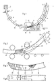
- Fig. 1, 2 is a mold of a sheet continuous caster, preferably for steel billets.
- the secondary cooling is indicated with spray nozzles.
- a few guide rollers 4 guide the cast strand 6 along the arcuate strand guide into a driving straightener 7.
- a rigid starting strand 9, which can be moved for example via a cable 8, has reached the decoupling position with its starting head 10.
- a roll 12 that can be adjusted in the direction of an arrow 11 toward the continuous track starts to separate the cast strand 6 from the starting head 10.
- the starting support 9 moves along its longitudinal axis 14 during the uncoupling.
- the starting head 10 can be detached from the cast strand 6 by a pivoting movement in the direction of arrow 15.
- a curved cavity is provided as the coupling part 16 in the end face of the starting head 10, in which a corresponding coupling hook made of the cast metal solidifies at the start of casting.
- the starting head 10 is articulated on the rigid starting strand 9 about an axis 19 arranged transversely to the strand running direction 18.
- the adjustable roller 12 presses in the direction of arrow 11 onto the start-up head 10 and pivots it from the arcuate longitudinal axis 14 of the start-up strand 9 away to the outside.
- the start-up line 9 is supported by a support frame 17, which can be arranged near the roller 12, in order to avoid bending on the start-up line 9.
- Fig. 2 20 is shown a starting head with a coupling part 21 in the form of a bent finger.
- a solid line shows a situation immediately before the separation process and a dash-dotted line shows a situation during the separation process.
- An adjustable roller 23 presses on the moving start-up head 20. It first releases the cast coupling, then it separates the start-up head 20 from the cast strand 22 and begins during the separating process before the roller 23 touches the cast strand 22, the latter in the horizontal position to push and judge.
- the counterweight head 20 is provided with a counterweight 24 for the automatic swiveling back of the starter head 20 after complete decoupling into the aligned position with respect to the axial longitudinal axis.
- a start-up strand cassette is indicated, which is preceded by a roller 27.
- a resilient latching element 31 is shown between a starting head 30 and a starting strand 32 in the form of a spring-loaded ball. So that the starting head 30 is pivoted back into the axial position from the pivoted position during the return journey into a cold-strand cassette, the roller 27 (FIG. 2) arranged at the entrance of the cold-strand cassette 26 (FIG. 2) takes over the task of tipping back.
- the start-up head 30 can on the one hand be arranged so as to be movable about a pivoting plane defined by axis 33 and on the other hand about a plane perpendicular to the pivoting plane. This additional mobility is made possible by axis 34 in the example shown. But it can also be achieved by other means. To move such a start-up head into the mold, it is advantageous if a conical centering piece, which can be removed after the entry, is placed over the coupling part.
- the continuous caster according to the invention can also advantageously be used for blooms.
Landscapes
- Engineering & Computer Science (AREA)
- Mechanical Engineering (AREA)
- Continuous Casting (AREA)
- Casting Devices For Molds (AREA)
Priority Applications (1)
| Application Number | Priority Date | Filing Date | Title |
|---|---|---|---|
| AT83106665T ATE18727T1 (de) | 1982-07-16 | 1983-07-07 | Bogenstranggiessanlage mit bogenfoermigem, starrem anfahrstrang und verfahren zum betrieb einer solchen anlage. |
Applications Claiming Priority (2)
| Application Number | Priority Date | Filing Date | Title |
|---|---|---|---|
| CH4342/82 | 1982-07-16 | ||
| CH4342/82A CH658210A5 (de) | 1982-07-16 | 1982-07-16 | Bogenstranggiessanlage mit bogenfoermigem, starrem anfahrstrang und verfahren zum betrieb einer solchen anlage. |
Publications (3)
| Publication Number | Publication Date |
|---|---|
| EP0099076A2 EP0099076A2 (de) | 1984-01-25 |
| EP0099076A3 EP0099076A3 (en) | 1984-07-18 |
| EP0099076B1 true EP0099076B1 (de) | 1986-03-26 |
Family
ID=4274296
Family Applications (1)
| Application Number | Title | Priority Date | Filing Date |
|---|---|---|---|
| EP83106665A Expired EP0099076B1 (de) | 1982-07-16 | 1983-07-07 | Bogenstranggiessanlage mit bogenförmigem, starrem Anfahrstrang und Verfahren zum Betrieb einer solchen Anlage |
Country Status (8)
| Country | Link |
|---|---|
| US (1) | US4561490A (enExample) |
| EP (1) | EP0099076B1 (enExample) |
| JP (1) | JPS5924557A (enExample) |
| AT (1) | ATE18727T1 (enExample) |
| CA (1) | CA1211272A (enExample) |
| CH (1) | CH658210A5 (enExample) |
| DE (1) | DE3362684D1 (enExample) |
| ES (1) | ES524548A0 (enExample) |
Cited By (1)
| Publication number | Priority date | Publication date | Assignee | Title |
|---|---|---|---|---|
| DE102015210865A1 (de) | 2015-05-06 | 2016-11-10 | Sms Group Gmbh | Gieß-Walz-Anlage und Verfahren zu deren Betrieb |
Families Citing this family (5)
| Publication number | Priority date | Publication date | Assignee | Title |
|---|---|---|---|---|
| JPS63237495A (ja) * | 1987-03-26 | 1988-10-03 | 古河電気工業株式会社 | 複合回路基板 |
| CH675975A5 (enExample) * | 1988-03-18 | 1990-11-30 | Concast Standard Ag | |
| CH679650A5 (enExample) * | 1989-04-24 | 1992-03-31 | Concast Standard Ag | |
| JP2542493B2 (ja) * | 1995-04-28 | 1996-10-09 | 古河電気工業株式会社 | 複合回路基板 |
| CN110252982B (zh) * | 2019-06-28 | 2021-05-04 | 上海二十冶建设有限公司 | 方坯连铸机扇形段安装调整方法 |
Family Cites Families (6)
| Publication number | Priority date | Publication date | Assignee | Title |
|---|---|---|---|---|
| US3080625A (en) * | 1958-02-21 | 1963-03-12 | British Iron Steel Research | Continuous casting apparatus |
| US3344844A (en) * | 1964-08-10 | 1967-10-03 | Koppers Co Inc | Apparatus for handling a curved continuous casting starting bar |
| AT347057B (de) * | 1976-07-08 | 1978-12-11 | Voest Ag | Stranggiessanlage |
| DE2714338C3 (de) * | 1977-03-31 | 1984-08-02 | Mannesmann AG, 4000 Düsseldorf | Anfahrstrang-Transportvorrichtung |
| US4291748A (en) * | 1980-02-25 | 1981-09-29 | Concast Incorporated | Dummy bar for a continuous casting machine |
| SU923731A1 (ru) * | 1980-09-19 | 1982-04-30 | Nii Tyazhelogo Mash | Устройство для отделения затравки от слитка машины непрерывного литья заготовок • 1 |
-
1982
- 1982-07-16 CH CH4342/82A patent/CH658210A5/de not_active IP Right Cessation
-
1983
- 1983-07-05 US US06/510,964 patent/US4561490A/en not_active Expired - Lifetime
- 1983-07-07 EP EP83106665A patent/EP0099076B1/de not_active Expired
- 1983-07-07 AT AT83106665T patent/ATE18727T1/de not_active IP Right Cessation
- 1983-07-07 DE DE8383106665T patent/DE3362684D1/de not_active Expired
- 1983-07-13 JP JP58126292A patent/JPS5924557A/ja active Granted
- 1983-07-15 ES ES524548A patent/ES524548A0/es active Granted
- 1983-07-15 CA CA000432517A patent/CA1211272A/en not_active Expired
Cited By (1)
| Publication number | Priority date | Publication date | Assignee | Title |
|---|---|---|---|---|
| DE102015210865A1 (de) | 2015-05-06 | 2016-11-10 | Sms Group Gmbh | Gieß-Walz-Anlage und Verfahren zu deren Betrieb |
Also Published As
| Publication number | Publication date |
|---|---|
| JPS5924557A (ja) | 1984-02-08 |
| DE3362684D1 (en) | 1986-04-30 |
| CA1211272A (en) | 1986-09-16 |
| ES8405651A1 (es) | 1984-06-16 |
| US4561490A (en) | 1985-12-31 |
| CH658210A5 (de) | 1986-10-31 |
| JPH0440101B2 (enExample) | 1992-07-01 |
| ATE18727T1 (de) | 1986-04-15 |
| EP0099076A3 (en) | 1984-07-18 |
| ES524548A0 (es) | 1984-06-16 |
| EP0099076A2 (de) | 1984-01-25 |
Similar Documents
| Publication | Publication Date | Title |
|---|---|---|
| CH345121A (de) | Verfahren zum kontinuierlichen Giessen eines Metallstranges und Stranggiessanlage zur Durchführung dieses Verfahrens | |
| EP0711724A1 (de) | Trenneinrichtung zum Abtrennen perforierter Schlauchabschnitte | |
| EP0099076B1 (de) | Bogenstranggiessanlage mit bogenförmigem, starrem Anfahrstrang und Verfahren zum Betrieb einer solchen Anlage | |
| DE3433685A1 (de) | Vorrichtung zum entgraten von werkstuecken | |
| DE3501716C2 (de) | Verfahren und Einrichtung zum Verstellen der Schmalseitenplatten einer Stranggießkokille beim Stranggießen von Metallen, insbesondere von Stahl | |
| DE3626638C2 (enExample) | ||
| CH658009A5 (de) | Verfahren und plattenkokille zum kuehlen und stuetzen eines stranges in einer plattenkokille einer stahlstranggiessanlage. | |
| DE2208635B2 (de) | Verfahren und vorrichtung zum einfahren des anfahrstranges in eine stranggiesskokille | |
| DE2714338C3 (de) | Anfahrstrang-Transportvorrichtung | |
| DE2758514C3 (de) | Stahlstranggießkokille für Knüppel- und Vorblockstränge | |
| EP0060484B1 (de) | Führungseinrichtung für einen starren Kaltstrang | |
| EP0332939B1 (de) | Bogenstranggiessanlage für Knüppelstränge | |
| DE3219161C1 (de) | Verfahren und Einrichtung zum Entkuppeln des Anfahrstrangs vom Gußstrang bei Stranggießen von Metall, insbesondere von Stahl | |
| EP3377245B1 (de) | Angiessvorrichtung einer stranggiessanlage und deren betrieb | |
| DE3113037C2 (enExample) | ||
| EP0990504A1 (de) | Vorrichtung zum Extrudieren von Kunststoffrohren oder Profilen | |
| EP0334800A2 (de) | Anfahrkopf für eine Horizontal-Stranggiessanlage | |
| EP0110153B1 (de) | Brennschneidmaschine | |
| EP0128328B1 (de) | Verfahren zum Abtrennen des Schopfendes eines gegossenen Stranges mittels einer Schere in einer Stranggiessanlage | |
| DE2928783A1 (de) | Einrichtung zum trennen des anfahrstranges vom warmstrang in der strangfuehrungsbahn einer stranggiessanlage | |
| DE3840633C2 (de) | Vorrichtung zur Führung und Überleitung des durch Saum- bzw. Streifenscheren von einem Band abgetrennten Bandsaumes zur Saumteilschere | |
| EP0365776B1 (de) | Anordnung von Klemmbacken einer Brennschneidmaschine auf einer Stranggiessanlage | |
| EP0080998B1 (de) | Vorrichtung zum horizontalen Stranggiessen von Metallen oder Legierungen | |
| DE2636356C3 (de) | Vorrichtung zum Entfleischen von Tierhäuten | |
| DE3018052A1 (de) | Vorrichtung zum ziehen von rohren |
Legal Events
| Date | Code | Title | Description |
|---|---|---|---|
| PUAI | Public reference made under article 153(3) epc to a published international application that has entered the european phase |
Free format text: ORIGINAL CODE: 0009012 |
|
| AK | Designated contracting states |
Designated state(s): AT BE DE FR GB IT |
|
| PUAL | Search report despatched |
Free format text: ORIGINAL CODE: 0009013 |
|
| AK | Designated contracting states |
Designated state(s): AT BE DE FR GB IT |
|
| 17P | Request for examination filed |
Effective date: 19840614 |
|
| ITF | It: translation for a ep patent filed | ||
| GRAA | (expected) grant |
Free format text: ORIGINAL CODE: 0009210 |
|
| AK | Designated contracting states |
Kind code of ref document: B1 Designated state(s): AT BE DE FR GB IT |
|
| REF | Corresponds to: |
Ref document number: 18727 Country of ref document: AT Date of ref document: 19860415 Kind code of ref document: T |
|
| ET | Fr: translation filed | ||
| REF | Corresponds to: |
Ref document number: 3362684 Country of ref document: DE Date of ref document: 19860430 |
|
| PLBE | No opposition filed within time limit |
Free format text: ORIGINAL CODE: 0009261 |
|
| STAA | Information on the status of an ep patent application or granted ep patent |
Free format text: STATUS: NO OPPOSITION FILED WITHIN TIME LIMIT |
|
| 26N | No opposition filed | ||
| REG | Reference to a national code |
Ref country code: GB Ref legal event code: 732 |
|
| ITPR | It: changes in ownership of a european patent |
Owner name: CESSIONE;CONCAST STANDARD AG |
|
| ITTA | It: last paid annual fee | ||
| PGFP | Annual fee paid to national office [announced via postgrant information from national office to epo] |
Ref country code: AT Payment date: 20000612 Year of fee payment: 18 |
|
| PGFP | Annual fee paid to national office [announced via postgrant information from national office to epo] |
Ref country code: GB Payment date: 20000622 Year of fee payment: 18 |
|
| PGFP | Annual fee paid to national office [announced via postgrant information from national office to epo] |
Ref country code: BE Payment date: 20000704 Year of fee payment: 18 |
|
| PGFP | Annual fee paid to national office [announced via postgrant information from national office to epo] |
Ref country code: FR Payment date: 20010611 Year of fee payment: 19 |
|
| PGFP | Annual fee paid to national office [announced via postgrant information from national office to epo] |
Ref country code: DE Payment date: 20010625 Year of fee payment: 19 |
|
| PG25 | Lapsed in a contracting state [announced via postgrant information from national office to epo] |
Ref country code: GB Free format text: LAPSE BECAUSE OF NON-PAYMENT OF DUE FEES Effective date: 20010707 Ref country code: AT Free format text: LAPSE BECAUSE OF NON-PAYMENT OF DUE FEES Effective date: 20010707 |
|
| PG25 | Lapsed in a contracting state [announced via postgrant information from national office to epo] |
Ref country code: BE Free format text: LAPSE BECAUSE OF NON-PAYMENT OF DUE FEES Effective date: 20010731 |
|
| BERE | Be: lapsed |
Owner name: CONCAST STANDARD A.G. Effective date: 20010731 |
|
| GBPC | Gb: european patent ceased through non-payment of renewal fee |
Effective date: 20010707 |
|
| PG25 | Lapsed in a contracting state [announced via postgrant information from national office to epo] |
Ref country code: DE Free format text: LAPSE BECAUSE OF NON-PAYMENT OF DUE FEES Effective date: 20030201 |
|
| PG25 | Lapsed in a contracting state [announced via postgrant information from national office to epo] |
Ref country code: FR Free format text: LAPSE BECAUSE OF NON-PAYMENT OF DUE FEES Effective date: 20030331 |
|
| REG | Reference to a national code |
Ref country code: FR Ref legal event code: ST |