EP0099076B1 - Curved continuous-casting plant with curved rigid dummy bar and method of operating such a plant - Google Patents
Curved continuous-casting plant with curved rigid dummy bar and method of operating such a plant Download PDFInfo
- Publication number
- EP0099076B1 EP0099076B1 EP83106665A EP83106665A EP0099076B1 EP 0099076 B1 EP0099076 B1 EP 0099076B1 EP 83106665 A EP83106665 A EP 83106665A EP 83106665 A EP83106665 A EP 83106665A EP 0099076 B1 EP0099076 B1 EP 0099076B1
- Authority
- EP
- European Patent Office
- Prior art keywords
- starting
- head
- arc
- strand
- curved
- Prior art date
- Legal status (The legal status is an assumption and is not a legal conclusion. Google has not performed a legal analysis and makes no representation as to the accuracy of the status listed.)
- Expired
Links
Images
Classifications
-
- B—PERFORMING OPERATIONS; TRANSPORTING
- B22—CASTING; POWDER METALLURGY
- B22D—CASTING OF METALS; CASTING OF OTHER SUBSTANCES BY THE SAME PROCESSES OR DEVICES
- B22D11/00—Continuous casting of metals, i.e. casting in indefinite lengths
- B22D11/08—Accessories for starting the casting procedure
- B22D11/081—Starter bars
- B22D11/083—Starter bar head; Means for connecting or detaching starter bars and ingots
Definitions
- the invention relates to a continuous sheet caster with an arcuate, rigid start-up strand, wherein in the area of the straightening machine a roll that can be adjusted towards the strand path separates the cast strand from the start-up strand while maintaining the position of the longitudinal axis of the moving rigid start-up strand and a method for operating such a system.
- a start-up line is required to start up a continuous caster.
- the head of the start-up strand which is provided with a coupling part, closes the mold on its underside and creates a connection with the cast strand at the start of casting so that it can be pulled out of the mold and inserted into the driver.
- the start-up strand can be composed, for example, of individual links or constructed from other flexible constructions, or can consist of a rigid, arc-shaped piece of steel, which is generally approximately the length of a quarter circle.
- the starting strand moving along its longitudinal axis remains on its path of motion.
- the start-up head connected to the cast strand runs through the shears and is only separated from the end of the shear after the cropping cut and is reused.
- a new screw must be inserted in the cold strand head as a coupling element for the subsequent casting.
- This continuous caster has several disadvantages.
- the start-up head remaining at the end of the crimp which must be manually separated after each casting, provided with a new coupling part before each reuse, coupled to the start-up line and secured against falling out, causes additional costs.
- the top end cannot be properly aligned. be tet, because the strand does not lie on the straight roller bed during the time of the pressing process. Inaccurately directed top ends on the cast strand often cause disturbances when entering a subsequent pair of shears.
- a continuous sheet caster which describes a start-up line which consists of a rigid and a flexible part composed of links.
- the rigid and the flexible part each have a length of approximately half the circular strand guide.
- the start-up head of this start-up line is provided with a permanent coupling part, the uncoupling being effected by a relative movement between the cast strand and the start-up head transversely to the longitudinal axis of the line.
- this starting strand is only about half rigid, it fulfills two essential requirements of the rigid starting strand group.
- the uncoupling between the cast strand and the start-up strand is carried out on the non-directional warm strand and the rigid part of the start-up strand bridges larger sections of the secondary cooling zone below the mold that are not guided by the strand.
- This start-up strand which is rigid over half its length, is therefore to be assigned to the group of rigid start-up lines in terms of its function. Even with such systems, the top end of the cast strand cannot be properly directed during the uncoupling time. Depending on the force required to separate the cast coupling part from the start-up head, the start-up strand can suffer permanent deformation, which can cause difficulties when re-inserting the start-up strand into the mold.
- the invention is based on the object of using a rigid start-up line with a permanent coupling device in a continuous casting machine, which on the one hand ensures trouble-free decoupling between the permanent coupling part and the cast line, prevents bending of the rigid start-up line during decoupling, even at high casting speeds and at large casting speed changes of the strand caused by non-controllable spouts on the tundish, the uncoupling of the cast strand from Anfahrkopt does not cause any malfunctions and a perfect straightening of the head of the cast strand guarantees precise introduction into a subsequent pair of scissors.
- a start-up head provided with a permanent coupling part which can be released by pivoting movement is pivoted on the start-up line about an axis arranged transversely to the direction of the line run, and the employable roller exerts the force for decoupling the permanent clutch device on the pivotable start-up head in such a way that the latter starts up during the casting operation from its axial position pivoted away from the arcuate longitudinal axis of the starting strand.
- the process for operating this continuous sheet caster is characterized in that the contact force of the adjustable roller for decoupling is applied to a start-up head part which can be pivoted outward from the curved line with a permanent coupling and is released from the cast strand by pivoting the start-up head and that the decoupled start-up head is pivoted back in the direction of the longitudinal axis of the start-up line during the further movement of the start-up line.
- the arrangement according to the invention further reduces the bending forces acting on the rigid starting strand by the pivoting movement of the starting head when uncoupling, which serves to maintain its precise shape and increases the resulting accuracy of insertion into the mold. Furthermore, the distances covered during the decoupling process, which are caused by different casting speeds, can be eliminated as a disturbing factor within wide limits.
- the straightening process can also begin before the adjustable roller presses on the cast strand. When the hot strand reaches the positionable roll, the uncoupling has taken place and the roll only has the function of a straightening roll.
- the swiveling start-up head also facilitates insertion into the mold if, after a long period of operation, the guide precision for the start-up strand on the drive rollers has decreased due to natural wear and tear.
- the swiveling start-up head can also be inserted into the mold without problems under such circumstances.
- the swiveling start-up head can be swiveled back manually into the starting position and secured in the starting position with a shear bolt that can be sheared off by small forces.
- the starting head be assigned a device for automatic pivoting back into a position in alignment with the curved longitudinal axis of the rigid starting line.
- a device for the automatic pivoting back of the tilted head can consist, for example, of a counterweight attached to the head.
- Another advantageous device for the automatic pivoting back of the tilted start-up head can also consist of a deflection roller arranged at the cold-strand cassette entrance and a resilient snap-in element between the start-up head and the start-up strand. Both solutions ensure an axial positioning of the swiveling start-up head as the start-up line enters the strand guide and the mold.
- the specified time for the release process between the cast strand and the start-up head by the adjustable roller can be influenced by the choice of the length of the start-up head part that can be pivoted outwards. It is therefore particularly advantageous if the start-up head part, which can be pivoted outwards from the curved line, is at least 300 mm long.
- the starting head In the case of continuous casting plants, the lateral guidance of which for the rigid starting strand has become imprecise, for example due to wear, it can be advantageous if the starting head is arranged such that it can be moved about a plane perpendicular to the pivoting plane.
- the advantages of a start-up head movably connected by two swivel planes or by two mutually perpendicular shifting planes can also be exploited if the start-up head is provided with a conical, removable centering piece during the movement into the mold.
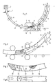
- Fig. 1, 2 is a mold of a sheet continuous caster, preferably for steel billets.
- the secondary cooling is indicated with spray nozzles.
- a few guide rollers 4 guide the cast strand 6 along the arcuate strand guide into a driving straightener 7.
- a rigid starting strand 9, which can be moved for example via a cable 8, has reached the decoupling position with its starting head 10.
- a roll 12 that can be adjusted in the direction of an arrow 11 toward the continuous track starts to separate the cast strand 6 from the starting head 10.
- the starting support 9 moves along its longitudinal axis 14 during the uncoupling.
- the starting head 10 can be detached from the cast strand 6 by a pivoting movement in the direction of arrow 15.
- a curved cavity is provided as the coupling part 16 in the end face of the starting head 10, in which a corresponding coupling hook made of the cast metal solidifies at the start of casting.
- the starting head 10 is articulated on the rigid starting strand 9 about an axis 19 arranged transversely to the strand running direction 18.
- the adjustable roller 12 presses in the direction of arrow 11 onto the start-up head 10 and pivots it from the arcuate longitudinal axis 14 of the start-up strand 9 away to the outside.
- the start-up line 9 is supported by a support frame 17, which can be arranged near the roller 12, in order to avoid bending on the start-up line 9.
- Fig. 2 20 is shown a starting head with a coupling part 21 in the form of a bent finger.
- a solid line shows a situation immediately before the separation process and a dash-dotted line shows a situation during the separation process.
- An adjustable roller 23 presses on the moving start-up head 20. It first releases the cast coupling, then it separates the start-up head 20 from the cast strand 22 and begins during the separating process before the roller 23 touches the cast strand 22, the latter in the horizontal position to push and judge.
- the counterweight head 20 is provided with a counterweight 24 for the automatic swiveling back of the starter head 20 after complete decoupling into the aligned position with respect to the axial longitudinal axis.
- a start-up strand cassette is indicated, which is preceded by a roller 27.
- a resilient latching element 31 is shown between a starting head 30 and a starting strand 32 in the form of a spring-loaded ball. So that the starting head 30 is pivoted back into the axial position from the pivoted position during the return journey into a cold-strand cassette, the roller 27 (FIG. 2) arranged at the entrance of the cold-strand cassette 26 (FIG. 2) takes over the task of tipping back.
- the start-up head 30 can on the one hand be arranged so as to be movable about a pivoting plane defined by axis 33 and on the other hand about a plane perpendicular to the pivoting plane. This additional mobility is made possible by axis 34 in the example shown. But it can also be achieved by other means. To move such a start-up head into the mold, it is advantageous if a conical centering piece, which can be removed after the entry, is placed over the coupling part.
- the continuous caster according to the invention can also advantageously be used for blooms.
Abstract
Description
Die Erfindung betrifft eine Bogenstranggiessanlage mit bogenförmigem, starrem Anfahrstrang, wobei im Bereich der Richtmaschine eine zur Strangbahn hin anstellbare Rolle den gegossenen Strang vom Anfahrstrang unter Beibehaltung der Position der Längsachse des sich bewegenden starren Anfahrstranges trennt und ein Verfahren zum Betrieb einer solchen Anlage.The invention relates to a continuous sheet caster with an arcuate, rigid start-up strand, wherein in the area of the straightening machine a roll that can be adjusted towards the strand path separates the cast strand from the start-up strand while maintaining the position of the longitudinal axis of the moving rigid start-up strand and a method for operating such a system.
Zum Anfahren einer Stranggiessanlage ist ein Anfahrstrang notwendig. Der mit einem Kupplungsteil versehene Kopf des Anfahrstranges verschliesst dabei die Kokille auf ihrer Unterseite und erzeugt bei Giessbeginn eine Verbindung mit dem gegossenen Strang, damit dieser aus der Kokille ausgezogen und in den Treiber eingeführt werden kann.A start-up line is required to start up a continuous caster. The head of the start-up strand, which is provided with a coupling part, closes the mold on its underside and creates a connection with the cast strand at the start of casting so that it can be pulled out of the mold and inserted into the driver.
Bei Bogenstranggiessanlagen kann der Anfahrstrang beispielsweise aus einzelnen Gliedern zusammengesetzt bzw. aus anderen flexiblen Konstruktionen aufgebaut sein oder aber aus einem starren bogenförmigen, in der Regel etwa die Länge eines Viertelkreises aufweisenden Stahlstückes bestehen.In continuous sheet casting systems, the start-up strand can be composed, for example, of individual links or constructed from other flexible constructions, or can consist of a rigid, arc-shaped piece of steel, which is generally approximately the length of a quarter circle.
Aus der US-A-3 344 844 ist die Anwendung eines bogenförmigen, starren Anfahrstranges in einer Kreisbogen-Stranggiessanlage bekannt. Dieser Anfahrstrang ist mit einem lösbaren Anfahrkopf versehen. Als Kupplungsteil weist der Anfahrkopf eine einsetzbare Schraube auf, die beim Angiessen vom flüssigen Stahl umgossen wird. Der Anfahrkopf selbst ist mit einem zweiten Kupplungselement versehen, das eine Ankupplung des Kopfes an den Anfahrstrang erlaubt. Im Bereich der Richtmaschine dieser Anlage ist eine zur Strangbahn hin anstellbare Rolle angeordnet. Für die Trennung des gegossenen Stranges vom Anfahrstrang drückt die anstellbäre Rolle auf den gegossenen Strang und klinkt dabei die Kupplung zwischen dem Anfahrkopf und dem Anfahrstrang aus. Während der Entkupplung verbleibt der sich entlang seiner Längsachse bewegende Anfahrstrang auf seiner Bewegungsbahn. Der mit dem gegossenen Strang verbundene Anfahrkopf läuft durch die Schere und wird erst nach dem Schopfenden-Schnitt vom Schopfende getrennt sowie einer Wiederverwendung zugeführt. Als Kupplungselement für den folgenden Guss muss eine neue Schraube in den Kaltstrangkopf eingesetzt werden. Diese Stranggiessanlage weist verschiedene Nachteile auf. Der am Schopfende verbleibende Anfahrkopf, der nach jedem Guss manuell getrennt, vor jedem Wiedergebrauch mit einem neuen Kupplungsteil versehen, am Anfahrstrang wieder angekuppelt und gegen ein Wegfallen gesichert werden muss, verursacht zusätzliche Kosten. Im weiteren kann bei dieser Anlage auch bei einem genauen Schaltimpuls für das Anstellen der Abdrückrolle an den gegossenen Strang das Schopfende nicht einwandfrei gerich- . tet werden, weil während der Zeit des Abdrückvorganges der Strang nicht auf dem geraden Rollenbett aufliegt. Ungenau gerichtete Schopfenden am gegossenen Strang verursachen häufig Störungen beim Einlauf in eine nachfolgende Schere.From US-A-3 344 844 the use of an arcuate, rigid start-up strand in a circular arc continuous caster is known. This start-up line is provided with a releasable start-up head. As a coupling part, the start-up head has an insertable screw, which is cast around by the molten steel during casting. The start-up head itself is provided with a second coupling element which allows the head to be coupled to the start-up line. In the area of the straightening machine of this system, a roll that can be adjusted towards the strand path is arranged. To separate the cast strand from the start-up strand, the adjustable roller presses on the cast strand and disengages the coupling between the start-up head and the start-up strand. During the uncoupling, the starting strand moving along its longitudinal axis remains on its path of motion. The start-up head connected to the cast strand runs through the shears and is only separated from the end of the shear after the cropping cut and is reused. A new screw must be inserted in the cold strand head as a coupling element for the subsequent casting. This continuous caster has several disadvantages. The start-up head remaining at the end of the crimp, which must be manually separated after each casting, provided with a new coupling part before each reuse, coupled to the start-up line and secured against falling out, causes additional costs. Furthermore, with this system, even with a precise switching impulse for placing the push-off roller on the cast strand, the top end cannot be properly aligned. be tet, because the strand does not lie on the straight roller bed during the time of the pressing process. Inaccurately directed top ends on the cast strand often cause disturbances when entering a subsequent pair of shears.
Aus der US-A-4 291 748 ist weiter eine Bogenstranggiessanlage bekannt, die einen Anfahrstrang beschreibt, der aus einem starren und einem gliederartig zusammengesetzten flexiblen Teil besteht. Der starre und der flexible Teil weisen je eine Länge von etwa der Hälfte der kreisförmigen Strangführung auf. Der Anfahrkopf dieses Anfahrstranges ist mit einem permanenten Kupplungsteil versehen, wobei die Entkupplung durch eine Relativbewegung zwischen dem gegossenen Strang und dem Anfahrkopf quer zur Stranglängsachse erfolgt. Obwohl dieser Anfahrstrang nur etwa zur Hälfte starr ist, erfüllt er zwei wesentliche Forderungen der Gruppe der starren Anfahrstränge. Die Entkupplung zwischen dem gegossenen Strang und dem Anfahrstrang wird am ungerichteten Warmstrang vorgenommen und der starre Anfahrstrangteil überbrückt grössere strangführungslose Abschnitte der Sekundärkühlzone unterhalb der Kokille. Dieser auf seiner halben Länge starre Anfahrstrang ist deshalb von seiner Funktion her gesehen der Gruppe der starren Anfahrstränge zuzuordnen. Auch bei solchen Anlagen kann während der Entkupplungszeit das Schopfende des gegossenen Stranges nicht einwandfrei gerichtet werden. Je nach der erforderlichen Kraft für die Trennung des gegossenen Kupplungsteiles vom Anfahrkopf kann der Anfahrstrang eine bleibende Verformung erleiden, was Schwierigkeiten beim Wiedereinführen des Anfahrstranges in die Kokille auslösen kann.From US-A-4 291 748 a continuous sheet caster is also known which describes a start-up line which consists of a rigid and a flexible part composed of links. The rigid and the flexible part each have a length of approximately half the circular strand guide. The start-up head of this start-up line is provided with a permanent coupling part, the uncoupling being effected by a relative movement between the cast strand and the start-up head transversely to the longitudinal axis of the line. Although this starting strand is only about half rigid, it fulfills two essential requirements of the rigid starting strand group. The uncoupling between the cast strand and the start-up strand is carried out on the non-directional warm strand and the rigid part of the start-up strand bridges larger sections of the secondary cooling zone below the mold that are not guided by the strand. This start-up strand, which is rigid over half its length, is therefore to be assigned to the group of rigid start-up lines in terms of its function. Even with such systems, the top end of the cast strand cannot be properly directed during the uncoupling time. Depending on the force required to separate the cast coupling part from the start-up head, the start-up strand can suffer permanent deformation, which can cause difficulties when re-inserting the start-up strand into the mold.
Der Erfindung liegt die Aufgabe zugrunde, in einer Bogenstranggiessanlage einen starren Anfahrstrang mit einer permanenten Ankupplungseinrichtung einzusetzen, der einerseits ein störungsfreies Entkuppeln zwischen dem permanenten Kupplungsteil und dem gegossenen Strang sicherstellt, eine Verbiegung des starren Anfahrstranges während des Entkuppelns vermeidet, auch bei hohen Giessgeschwindigkeiten und bei grossen, durch nicht regelbare Ausgüsse am Tundish verursachte Giessgeschwindigkeits- änderungen des Stranges das Entkuppeln des gegossenen Stranges von Anfahrkopt keine Störungen verursacht und ein einwandfreies Richten des Kopfes des gegossenen Stranges für eine präzise Einführung in eine nachfolgende Schere garantiert.The invention is based on the object of using a rigid start-up line with a permanent coupling device in a continuous casting machine, which on the one hand ensures trouble-free decoupling between the permanent coupling part and the cast line, prevents bending of the rigid start-up line during decoupling, even at high casting speeds and at large casting speed changes of the strand caused by non-controllable spouts on the tundish, the uncoupling of the cast strand from Anfahrkopt does not cause any malfunctions and a perfect straightening of the head of the cast strand guarantees precise introduction into a subsequent pair of scissors.
Nach der Erfindung wird dies dadurch erreicht, dass am Anfahrstrang ein mit einem durch Schwenkbewegung lösbaren permanenten Kupplungsteil versehener Anfahrkopf um eine quer zur Stranglaufrichtung angeordnete Achse schwenkbar angelenkt ist und die anstellbare Rolle die Kraft zum Entkuppeln der permanenten Kupplungseinrichtung auf den verschwenkbaren Anfahrkopf aufbringt, dass dieser während des Giessbetriebes aus seiner achsialen Lage von der bogenförmigen Längsachse des Anfahrstranges weg nach ausseh verschwenkt.According to the invention, this is achieved in that a start-up head provided with a permanent coupling part which can be released by pivoting movement is pivoted on the start-up line about an axis arranged transversely to the direction of the line run, and the employable roller exerts the force for decoupling the permanent clutch device on the pivotable start-up head in such a way that the latter starts up during the casting operation from its axial position pivoted away from the arcuate longitudinal axis of the starting strand.
Das Verfahren zum Betrieb dieser Bogenstranggiessanlage zeichnet sich dadurch aus, dass die Anstellkraft der anstellbaren Rolle zum Entkuppeln auf einen von der Bogenlinie weg nach aussen verschwenkbaren Anfahrkopfteil mit einer permanenten Kupplung aufgebracht und durch Verschwenkung der Anfahrkopf direkt vom gegossenen Strang gelöst wird und dass der entkuppelte Anfahrkopf während der Weiterbewegung des Anfahrstranges wieder in Richtung der Stranglängsachse des Anfahrstranges zurückgeschwenkt wird.The process for operating this continuous sheet caster is characterized in that the contact force of the adjustable roller for decoupling is applied to a start-up head part which can be pivoted outward from the curved line with a permanent coupling and is released from the cast strand by pivoting the start-up head and that the decoupled start-up head is pivoted back in the direction of the longitudinal axis of the start-up line during the further movement of the start-up line.
Durch die Anwendung eines permanenten Anfahrkopfes können gegenüber der Anwendung von nicht permanenten Anfahrköpfen alle zusätzlichen Umtriebe und Kosten vermieden werden. Die erfindungsgemässe Anordnung reduziert im weiteren durch die Schwenkbewegung des Anfahrkopfes beim Entkuppeln die auf den starren Anfahrstrang wirkenden Biegekräfte, was zur Erhaltung seiner genauen Formgebung dient und die dadurch bedingte Einführgenauigkeit in die Kokille erhöht. Im weiteren können die während des Entkupplungsvorganges zurückgelegten Wegstrecken, die durch untersqhiedliche Giessgeschwindigkeiten verursacht werden, als Störfaktor in weiten Grenzen ausgeschaltet werden. Auch der Richtvorgang kann beginnen, bevor die anstellbare Rolle auf den gegossenen Strang drückt. Wenn der Warmstrang die anstellbare Rolle erreicht, hat die Entkupplung stattgefunden, und die Rolle hat nur noch die Funktion einer Richtrolle zu erfüllen. Dies erzeugt ein einwandfreies Richten des, gegossenen Stranganfanges, was eine störungsfreie Einfahrt zwischen eng eingestellte Scherenmesser einer nachfolgenden Schere ermöglicht. In der Praxis hat sich im weiteren gezeigt, dass der schwenkbare Anfahrkopf auch das Einführen in die Kokille erleichtert, wenn sich nach langer Betriebszeit die Führungspräzision für den Anfahrstrang an den Treibrollen durch natürlichen Verschleiss verkleinert hat. Der verschwenkbare Anfahrkopf kann auch unter solchen Umständen störungsfrei in die Kokille eingefahren werden.By using a permanent start-up head, all additional activities and costs can be avoided compared to the use of non-permanent start-up heads. The arrangement according to the invention further reduces the bending forces acting on the rigid starting strand by the pivoting movement of the starting head when uncoupling, which serves to maintain its precise shape and increases the resulting accuracy of insertion into the mold. Furthermore, the distances covered during the decoupling process, which are caused by different casting speeds, can be eliminated as a disturbing factor within wide limits. The straightening process can also begin before the adjustable roller presses on the cast strand. When the hot strand reaches the positionable roll, the uncoupling has taken place and the roll only has the function of a straightening roll. This creates a perfect straightening of the cast strand beginning, which enables trouble-free entry between narrowly set shear blades of a subsequent shear. In practice it has also been shown that the swiveling start-up head also facilitates insertion into the mold if, after a long period of operation, the guide precision for the start-up strand on the drive rollers has decreased due to natural wear and tear. The swiveling start-up head can also be inserted into the mold without problems under such circumstances.
Nach einer Entkupplung zwischen dem Anfahrkopf und dem gegossenen Strang kann der verschwenkbare Anfahrkopf manuell in die Ausgangslage zurückgeschwenkt und mit einem durch kleine Kräfte abscherbaren Scherbolzen in der Ausgangslage gesichert werden. Gemäss einem weiteren Merkmal wird vorgeschlagen, dem Anfahrkopf eine Einrichtung für eine selbsttätige Rückverschwenkung in eine Position fluchtend zur gebogenen Längsachse des starren Anfahrstrangs zuzuordnen. Eine solche Einrichtung für die selbsttätige Rückverschwenkung des gekippten Anfahrkopfes kann beispielsweise aus einem am Anfahrkopf befestigten Gegengewicht bestehen. Eine weitere vorteilhafte Einrichtung für die selbsttätige Rückverschwenkung des gekippten Anfahrkopfes kann auch aus einer, am Kaltstrangkassetteneingang angeordneten Umlenkrolle und einem federnden Einrastelement zwischen dem Anfahrkopf und dem Anfahrstrang bestehen. Beide Lösungen stellen eine achsiale Positionierung des verschwenkbaren Anfahrkopfes während der Einfahrt des Anfahrstranges in die Strangführung und in die Kokille sicher.After uncoupling between the start-up head and the cast strand, the swiveling start-up head can be swiveled back manually into the starting position and secured in the starting position with a shear bolt that can be sheared off by small forces. According to a further feature, it is proposed that the starting head be assigned a device for automatic pivoting back into a position in alignment with the curved longitudinal axis of the rigid starting line. Such a device for the automatic pivoting back of the tilted head can consist, for example, of a counterweight attached to the head. Another advantageous device for the automatic pivoting back of the tilted start-up head can also consist of a deflection roller arranged at the cold-strand cassette entrance and a resilient snap-in element between the start-up head and the start-up strand. Both solutions ensure an axial positioning of the swiveling start-up head as the start-up line enters the strand guide and the mold.
Die Vorgabezeit für den Lösevorgang zwischen dem gegossenen Strang und dem Anfahrkopf durch die anstellbare Rolle kann durch die Wahl der Länge des nach aussen verschwenkbaren Anfahrkopfteiles beeinflusst werden. Es ist deshalb von besonderem Vorteil, wenn der von der Bogenlinie weg nach aussen verschwenkbare Anfahrkopfteil mindestens 300 mm lang ist.The specified time for the release process between the cast strand and the start-up head by the adjustable roller can be influenced by the choice of the length of the start-up head part that can be pivoted outwards. It is therefore particularly advantageous if the start-up head part, which can be pivoted outwards from the curved line, is at least 300 mm long.
Bei Stranggiessanlagen, deren seitliche Führung für den starren Anfahrstrang beispielsweise durch Verschleiss ungenau geworden ist, kann es von Vorteil sein, wenn der Anfahrkopf um eine zur Verschwenkebene rechtwinklig stehende Ebene beschränkt bewegbar angeordnet ist. Die Vorteile eines um zwei Schwenkebenen oder um zwei rechtwinklig zueinander stehende Verschiebeebenen beweglich verbundenen Anfahrkopfes können zusätzlich ausgenützt werden, wenn der Anfahrkopf während der Einfahrbewegung in die Kokille mit einem konischen, abhebbaren Zentrierstück versehen ist.In the case of continuous casting plants, the lateral guidance of which for the rigid starting strand has become imprecise, for example due to wear, it can be advantageous if the starting head is arranged such that it can be moved about a plane perpendicular to the pivoting plane. The advantages of a start-up head movably connected by two swivel planes or by two mutually perpendicular shifting planes can also be exploited if the start-up head is provided with a conical, removable centering piece during the movement into the mold.
Im Nachfolgenden werden anhand von Figuren Ausführungsbeispiele beschrieben. Dabei zeigen :
- Figur 1 eine schematische Seitenansicht einer Bogenstranggiessanlage,
Figur 2 eine schematische Seitenansicht einer Treibrichtmaschine,- Figur 3 eine Seitenansicht eines Anfahrkopfes und
Figur 4 eine Draufsicht auf Fig. 3.
- FIG. 1 shows a schematic side view of a continuous sheet caster,
- FIG. 2 shows a schematic side view of a driving leveler,
- Figure 3 is a side view of a start head and
- FIG. 4 shows a top view of FIG. 3.
In Fig. 1 ist mit 2 eine Kokille einer Bogenstranggiessanlage, vorzugsweise für Stahlknüppel, dargestellt. Mit Sprühdüsen ist die Sekundärkühlung angedeutet. Einige wenige Führungsrollen 4 führen den gegossenen Strang 6 entlang der bogenförmigen Strangführung in eine Treibrichtmaschine 7. Ein starrer Anfahrstrang 9, der beispielsweise über ein Kabel 8 bewegt werden kann, hat mit seinem Anfahrkopf 10 die Entkupplungsposition erreicht. Eine in Richtung eines Pfeiles 11 zur-Strangbahn hin anstellbare Rolle 12 beginnt den gegossenen Strang 6 vom Anfahrkopf 10 zu trennen. Der Anfahrstrag 9 bewegt sich während der Entkupplung entlang seiner Längsachse 14.In Fig. 1, 2 is a mold of a sheet continuous caster, preferably for steel billets. The secondary cooling is indicated with spray nozzles. A
Der Anfahrkopf 10 ist durch eine Schwenkbewegung in Richtung des Pfeiles 15 vom gegossenen Strang 6 lösbar. in diesem Beispiel ist als Kupplungsteil 16 ein gebogener Hohlraum in der Stirnseite des Anfahrkopfes 10 vorgesehen, in welchem bei Giessbeginn ein entsprechender Kupplungshaken aus dem Giessmetall erstarrt. Der Anfahrkopf 10 ist um eine quer zur Stranglaufrichtung 18 angeordnete Achse 19 schwenkbar am starren Anfahrstrang 9 angelenkt. Zum Entkuppeln des Anfahrkopfes 10 vom gegossenen Strang 6 drückt die anstellbare Rolle 12 in Richtung des Pfeiles 11 auf den Anfahrkopf 10 und verschwenkt dabei diesen von der bogenförmigen Längsachse 14 des Anfahrstranges 9 weg nach aussen. Der Anfahrstrang 9 wird durch einen Stützbock 17, der nahe der Rolle 12 angeordnet sein kann, abgestützt, um Verbiegungen am Anfahrstrang 9 zu vermeiden.The starting
In Fig. 2 ist mit 20 ein Anfahrkopf mit einem Kupplungsteil 21 in der Form eines gebogenen Fingers dargestellt. Mit ausgezogenen Linien ist eine Situation unmittelbar vor Beginn des Trennvorganges und mit strichpunktierten Linien ist eine Situation während des Trennvorganges dargestellt. Eine anstellbare Rolle 23 drückt auf den sich bewegenden Anfahrkopf 20. Sie löst zuerst die gegossene Kupplung, anschliessend trennt sie den Anfahrkopf 20 vom gegossenen Strang 22 und beginnt während des Trennvorganges, bevor die Rolle 23 den gegossenen Strang 22 berührt, diesen in die waagrechte Lage zu drücken und zu richten. Für die selbsttätige Rückschwenkung des Anfahrkopfes 20 nach vollständiger Entkupplung in die fluchtende Position zur achsialen Längsachse ist der Anfahrkopf 20 mit einem Gegengewicht 24 versehen. Dieses um eine Achse 25 eine Rückschwenkbewegung erzeugende Gegengewicht 24 hält den Anfahrkopf 20 eines starren Anfahrstranges 28 auch während einer Einfahrbewegung in die Kokille in seiner achsialen Lage fest. Mit 26 ist eine Anfahrstrangkassette angedeutet, welcher eine Rolle 27 vorgeordnet ist.In Fig. 2, 20 is shown a starting head with a
In Fig. 3 und 4 ist als Alternative zum Gegengewicht 24 (Fig. 2) ein federndes Einrastelement 31 zwischen einem Anfahrkopf 30 und einem Anfahrstrang 32 in Form einer abgefederten Kugel dargestellt. Damit der Anfahrkopf 30 aus der verschwenkten Position während der Rückfahrt in eine Kaltstrangkassette wieder in die achsiäle Lage zurückverschwenkt wird, übernimmt die am Eingang der Kaltstrangkassette 26 (Fig. 2) angeordnete Rolle 27 (Fig. 2) die Aufgabe des Rückkippens. Wenn für die Einführung des Anfahrkopfes 30 in die Kokille eine beschränkte allseitige Beweglichkeit des Anfahrkopfes 30 erwünscht ist, kann der Anfahrkopf 30 einerseits um eine durch Achse 33 definierte Verschwenkebene und anderseits um eine rechtwinklig zur Verschwenkebene stehende Ebene beschränkt bewegbar angeordnet werden. Diese zusätzliche Bewegbarkeit wird im gezeichneten Beispiel durch Achse 34 ermöglicht. Sie kann aber auch durch andere Mittel erreicht werden. Zum Einfahren eines solchen Anfahrkopfes in die Kokille ist es von Vorteil, wenn diesem über dem Kupplungsteil ein konisches, nach der Einfahrt abnehmbares Zentrierstück aufgesetzt wird.3 and 4, as an alternative to the counterweight 24 (FIG. 2), a
Anstelle der in den Beispielen beschriebenen Anfahrköpfe können auch andere, durch Schwenk- oder Kippbewegungen lösbare permanente Kupplungen verwendet werden.Instead of the starting heads described in the examples, other permanent couplings which can be released by swiveling or tilting movements can also be used.
Die erfindungsgemässe Stranggiessanlage kann mit Vorteil auch für Vorblockformate eingesetzt werden.The continuous caster according to the invention can also advantageously be used for blooms.
Claims (7)
Priority Applications (1)
| Application Number | Priority Date | Filing Date | Title |
|---|---|---|---|
| AT83106665T ATE18727T1 (en) | 1982-07-16 | 1983-07-07 | ARC CONTINUOUS CASTING PLANT WITH ARCH-FORMED, RIGID LAUNCH STREAM AND METHOD FOR OPERATING SUCH A PLANT. |
Applications Claiming Priority (2)
| Application Number | Priority Date | Filing Date | Title |
|---|---|---|---|
| CH4342/82 | 1982-07-16 | ||
| CH4342/82A CH658210A5 (en) | 1982-07-16 | 1982-07-16 | ARC CONTINUOUS CASTING SYSTEM WITH ARC-SHAPED, RIGID START-UP STRAND AND METHOD FOR OPERATING SUCH A SYSTEM. |
Publications (3)
| Publication Number | Publication Date |
|---|---|
| EP0099076A2 EP0099076A2 (en) | 1984-01-25 |
| EP0099076A3 EP0099076A3 (en) | 1984-07-18 |
| EP0099076B1 true EP0099076B1 (en) | 1986-03-26 |
Family
ID=4274296
Family Applications (1)
| Application Number | Title | Priority Date | Filing Date |
|---|---|---|---|
| EP83106665A Expired EP0099076B1 (en) | 1982-07-16 | 1983-07-07 | Curved continuous-casting plant with curved rigid dummy bar and method of operating such a plant |
Country Status (8)
| Country | Link |
|---|---|
| US (1) | US4561490A (en) |
| EP (1) | EP0099076B1 (en) |
| JP (1) | JPS5924557A (en) |
| AT (1) | ATE18727T1 (en) |
| CA (1) | CA1211272A (en) |
| CH (1) | CH658210A5 (en) |
| DE (1) | DE3362684D1 (en) |
| ES (1) | ES524548A0 (en) |
Cited By (1)
| Publication number | Priority date | Publication date | Assignee | Title |
|---|---|---|---|---|
| DE102015210865A1 (en) | 2015-05-06 | 2016-11-10 | Sms Group Gmbh | Casting-rolling plant and method for its operation |
Families Citing this family (5)
| Publication number | Priority date | Publication date | Assignee | Title |
|---|---|---|---|---|
| JPS63237495A (en) * | 1987-03-26 | 1988-10-03 | 古河電気工業株式会社 | Composite circuit board |
| CH675975A5 (en) * | 1988-03-18 | 1990-11-30 | Concast Standard Ag | |
| CH679650A5 (en) * | 1989-04-24 | 1992-03-31 | Concast Standard Ag | |
| JP2542493B2 (en) * | 1995-04-28 | 1996-10-09 | 古河電気工業株式会社 | Composite circuit board |
| CN110252982B (en) * | 2019-06-28 | 2021-05-04 | 上海二十冶建设有限公司 | Method for installing and adjusting fan-shaped section of billet continuous casting machine |
Family Cites Families (6)
| Publication number | Priority date | Publication date | Assignee | Title |
|---|---|---|---|---|
| US3080625A (en) * | 1958-02-21 | 1963-03-12 | British Iron Steel Research | Continuous casting apparatus |
| US3344844A (en) * | 1964-08-10 | 1967-10-03 | Koppers Co Inc | Apparatus for handling a curved continuous casting starting bar |
| AT347057B (en) * | 1976-07-08 | 1978-12-11 | Voest Ag | CONTINUOUS CASTING PLANT |
| DE2714338C3 (en) * | 1977-03-31 | 1984-08-02 | Mannesmann AG, 4000 Düsseldorf | Start-up line transport device |
| US4291748A (en) * | 1980-02-25 | 1981-09-29 | Concast Incorporated | Dummy bar for a continuous casting machine |
| SU923731A1 (en) * | 1980-09-19 | 1982-04-30 | Nii Tyazhelogo Mash | Metal continuous casting machine apparatus for separating dummy bar from ingot |
-
1982
- 1982-07-16 CH CH4342/82A patent/CH658210A5/en not_active IP Right Cessation
-
1983
- 1983-07-05 US US06/510,964 patent/US4561490A/en not_active Expired - Lifetime
- 1983-07-07 DE DE8383106665T patent/DE3362684D1/en not_active Expired
- 1983-07-07 EP EP83106665A patent/EP0099076B1/en not_active Expired
- 1983-07-07 AT AT83106665T patent/ATE18727T1/en not_active IP Right Cessation
- 1983-07-13 JP JP58126292A patent/JPS5924557A/en active Granted
- 1983-07-15 CA CA000432517A patent/CA1211272A/en not_active Expired
- 1983-07-15 ES ES524548A patent/ES524548A0/en active Granted
Cited By (1)
| Publication number | Priority date | Publication date | Assignee | Title |
|---|---|---|---|---|
| DE102015210865A1 (en) | 2015-05-06 | 2016-11-10 | Sms Group Gmbh | Casting-rolling plant and method for its operation |
Also Published As
| Publication number | Publication date |
|---|---|
| CA1211272A (en) | 1986-09-16 |
| JPH0440101B2 (en) | 1992-07-01 |
| US4561490A (en) | 1985-12-31 |
| ES8405651A1 (en) | 1984-06-16 |
| EP0099076A3 (en) | 1984-07-18 |
| CH658210A5 (en) | 1986-10-31 |
| DE3362684D1 (en) | 1986-04-30 |
| ES524548A0 (en) | 1984-06-16 |
| JPS5924557A (en) | 1984-02-08 |
| ATE18727T1 (en) | 1986-04-15 |
| EP0099076A2 (en) | 1984-01-25 |
Similar Documents
| Publication | Publication Date | Title |
|---|---|---|
| CH345121A (en) | Process for the continuous casting of a metal strand and continuous casting plant for carrying out this process | |
| EP0099076B1 (en) | Curved continuous-casting plant with curved rigid dummy bar and method of operating such a plant | |
| DE3433685A1 (en) | DEVICE FOR DEBURRING WORKPIECES | |
| DE3626638C2 (en) | ||
| DE2208635B2 (en) | METHOD AND DEVICE FOR RETRACTING THE DRIVE LINE INTO A CONTINUOUS CASTING GRILL | |
| DE2714338C3 (en) | Start-up line transport device | |
| DE2758514C3 (en) | Continuous steel casting mold for billet and bloom strands | |
| EP0332939B1 (en) | Bow-type continuous casting plant for billets | |
| EP0060484B1 (en) | Installation for guiding a rigid starting bar | |
| DE3219161C1 (en) | Method and device for decoupling the dummy bar from the cast strand in the continuous casting of metal, especially steel | |
| DE4032787A1 (en) | DEVICE FOR CONNECTING A PIPE TO THE SPOUT OF A METAL MELTING CONTAINER | |
| EP1285741A1 (en) | Apparatus for use in a calender for producing a plastic sheet and process to change an endless belt | |
| EP3377245B1 (en) | Casting starting device of a continuous casting line and operation thereof | |
| DE3113037C2 (en) | ||
| EP0110153B1 (en) | Torch cutting device | |
| EP0128328B1 (en) | Method of separating the crop end of a cast strand by a shear in a continuous-casting plant | |
| EP0035988A1 (en) | Arrangement for separating a starter bar from a cast strand in a continuous casting plant | |
| DE2928783A1 (en) | DEVICE FOR SEPARATING THE STARTING STRAND FROM THE WARM STRING IN THE STRAND GUIDE OF A CONTINUOUS CASTING SYSTEM | |
| DE3840633C2 (en) | Device for guiding and transferring the band hem, which is separated from a band by hem or strip scissors, to the parting scissors | |
| DE2629453A1 (en) | Flexible starting bar - for continuous casting apparatus, is gear-rack supported in storage position | |
| EP0080998B1 (en) | Installation for the horizontal continuous casting of metals or alloys | |
| EP0334800A2 (en) | Dummy bar head for a horizontal continuous casting plant | |
| DE3018052A1 (en) | DEVICE FOR PULLING TUBES | |
| DE3150175A1 (en) | Apparatus for the continuous casting of metals | |
| DE2748690C2 (en) | Device for releasing the starting head of a starting strand in a continuous caster |
Legal Events
| Date | Code | Title | Description |
|---|---|---|---|
| PUAI | Public reference made under article 153(3) epc to a published international application that has entered the european phase |
Free format text: ORIGINAL CODE: 0009012 |
|
| AK | Designated contracting states |
Designated state(s): AT BE DE FR GB IT |
|
| PUAL | Search report despatched |
Free format text: ORIGINAL CODE: 0009013 |
|
| AK | Designated contracting states |
Designated state(s): AT BE DE FR GB IT |
|
| 17P | Request for examination filed |
Effective date: 19840614 |
|
| ITF | It: translation for a ep patent filed |
Owner name: BARZANO' E ZANARDO MILANO S.P.A. |
|
| GRAA | (expected) grant |
Free format text: ORIGINAL CODE: 0009210 |
|
| AK | Designated contracting states |
Kind code of ref document: B1 Designated state(s): AT BE DE FR GB IT |
|
| REF | Corresponds to: |
Ref document number: 18727 Country of ref document: AT Date of ref document: 19860415 Kind code of ref document: T |
|
| ET | Fr: translation filed | ||
| REF | Corresponds to: |
Ref document number: 3362684 Country of ref document: DE Date of ref document: 19860430 |
|
| PLBE | No opposition filed within time limit |
Free format text: ORIGINAL CODE: 0009261 |
|
| STAA | Information on the status of an ep patent application or granted ep patent |
Free format text: STATUS: NO OPPOSITION FILED WITHIN TIME LIMIT |
|
| 26N | No opposition filed | ||
| REG | Reference to a national code |
Ref country code: GB Ref legal event code: 732 |
|
| ITPR | It: changes in ownership of a european patent |
Owner name: CESSIONE;CONCAST STANDARD AG |
|
| ITTA | It: last paid annual fee | ||
| PGFP | Annual fee paid to national office [announced via postgrant information from national office to epo] |
Ref country code: AT Payment date: 20000612 Year of fee payment: 18 |
|
| PGFP | Annual fee paid to national office [announced via postgrant information from national office to epo] |
Ref country code: GB Payment date: 20000622 Year of fee payment: 18 |
|
| PGFP | Annual fee paid to national office [announced via postgrant information from national office to epo] |
Ref country code: BE Payment date: 20000704 Year of fee payment: 18 |
|
| PGFP | Annual fee paid to national office [announced via postgrant information from national office to epo] |
Ref country code: FR Payment date: 20010611 Year of fee payment: 19 |
|
| PGFP | Annual fee paid to national office [announced via postgrant information from national office to epo] |
Ref country code: DE Payment date: 20010625 Year of fee payment: 19 |
|
| PG25 | Lapsed in a contracting state [announced via postgrant information from national office to epo] |
Ref country code: GB Free format text: LAPSE BECAUSE OF NON-PAYMENT OF DUE FEES Effective date: 20010707 Ref country code: AT Free format text: LAPSE BECAUSE OF NON-PAYMENT OF DUE FEES Effective date: 20010707 |
|
| PG25 | Lapsed in a contracting state [announced via postgrant information from national office to epo] |
Ref country code: BE Free format text: LAPSE BECAUSE OF NON-PAYMENT OF DUE FEES Effective date: 20010731 |
|
| BERE | Be: lapsed |
Owner name: CONCAST STANDARD A.G. Effective date: 20010731 |
|
| GBPC | Gb: european patent ceased through non-payment of renewal fee |
Effective date: 20010707 |
|
| PG25 | Lapsed in a contracting state [announced via postgrant information from national office to epo] |
Ref country code: DE Free format text: LAPSE BECAUSE OF NON-PAYMENT OF DUE FEES Effective date: 20030201 |
|
| PG25 | Lapsed in a contracting state [announced via postgrant information from national office to epo] |
Ref country code: FR Free format text: LAPSE BECAUSE OF NON-PAYMENT OF DUE FEES Effective date: 20030331 |
|
| REG | Reference to a national code |
Ref country code: FR Ref legal event code: ST |