EP0098527A2 - Véhicule routier du type fourgon bâché - Google Patents
Véhicule routier du type fourgon bâché Download PDFInfo
- Publication number
- EP0098527A2 EP0098527A2 EP83106365A EP83106365A EP0098527A2 EP 0098527 A2 EP0098527 A2 EP 0098527A2 EP 83106365 A EP83106365 A EP 83106365A EP 83106365 A EP83106365 A EP 83106365A EP 0098527 A2 EP0098527 A2 EP 0098527A2
- Authority
- EP
- European Patent Office
- Prior art keywords
- tarpaulin
- rope
- road vehicle
- vehicle according
- hook
- Prior art date
- Legal status (The legal status is an assumption and is not a legal conclusion. Google has not performed a legal analysis and makes no representation as to the accuracy of the status listed.)
- Granted
Links
Images
Classifications
-
- B—PERFORMING OPERATIONS; TRANSPORTING
- B60—VEHICLES IN GENERAL
- B60J—WINDOWS, WINDSCREENS, NON-FIXED ROOFS, DOORS, OR SIMILAR DEVICES FOR VEHICLES; REMOVABLE EXTERNAL PROTECTIVE COVERINGS SPECIALLY ADAPTED FOR VEHICLES
- B60J7/00—Non-fixed roofs; Roofs with movable panels, e.g. rotary sunroofs
- B60J7/08—Non-fixed roofs; Roofs with movable panels, e.g. rotary sunroofs of non-sliding type, i.e. movable or removable roofs or panels, e.g. let-down tops or roofs capable of being easily detached or of assuming a collapsed or inoperative position
- B60J7/10—Non-fixed roofs; Roofs with movable panels, e.g. rotary sunroofs of non-sliding type, i.e. movable or removable roofs or panels, e.g. let-down tops or roofs capable of being easily detached or of assuming a collapsed or inoperative position readily detachable, e.g. tarpaulins with frames, or fastenings for tarpaulins
- B60J7/102—Readily detachable tarpaulins, e.g. for utility vehicles; Frames therefor
- B60J7/104—Fastening means for tarpaulins
Definitions
- the innovation relates to a road vehicle with an open box body, which is covered by a tarpaulin optionally placed over a frame or over a bow, the tarpaulin being lashed to the outside of the upper edges of the box body by means of a removable fastening.
- Tarpaulin fastenings in road vehicles are often designed such that holes are arranged on the lower edges of the tarpaulin covering the side walls of the box body, for example holes or the like via plug-in eyelets stuck to the box body. pulled and secured, for example, by means of a rope pulled through the eyelets.
- the only advantage of such tarpaulin attachments is that the tarpaulin is secured and can also be sealed. Attaching the tarpaulin and pulling in the rope take a lot of work and thus also time, as well as when loosening the tarpaulin. With such tarpaulin fastenings it is also not ensured that the tarpaulin, which can expand or distort in use, is lashed down with the greatest possible tension.
- a road vehicle of the generic type is characterized in that an elastic rope is stretched between the rope holders attached to both ends of the edge side underneath the upper edge on the outer sides of the box side and parallel to the edge adjacent lower edge of the tarpaulin one or more hooks are fastened at intervals from one another, to which retaining lugs on the box wall are assigned offset in the course of the tensioned rope.
- the elastic rope In a road vehicle with a tarpaulin attachment of the aforementioned type, the elastic rope is permanently and captively connected to the box body. A rope can be stretched for one side of the box - however, there is the option of tensioning the rope over two or more assembly sides with appropriate guidance around the corner edges. Opening and closing the tarpaulin on any side is easily and quickly possible at any time by obliquely bracing the elastic rope firmly connected at its ends to the box structure, namely obliquely bracing between opposite hooks or retaining lugs arranged on the box structure and tarpaulin. This has the advantage that each The tarpaulin side can be opened quickly and easily completely or only partially and closed.
- a partial closing is interesting when some elongated parts, such as strips or pipes, are to be transported that protrude beyond the box structure.
- Another advantage is achieved that due to the tension with an elastic rope the tarpaulin is kept constantly under tension in the closed state and also if it stretches or warps over time due to the elastic rope tension firmly to the base or the Bow is tightened. Even during the journey, the elastic tensioning reduces or even completely prevents the curvature of the tarpaulin, which can often be observed under the influence of the wind, at various points.
- the elastic rope is provided at its ends with a thickening with which it is inserted into a receiving cavity of a rope holder.
- the rope holder is advantageously essentially designed as a box open to the support surface for receiving the final thickening of the rope, on a narrow wall it is provided with a recess for receiving the rope cross-section.
- the rope holder is also advantageously provided with a projection of its outer cover beyond a narrow side, so that it can also serve as a retaining lug.
- the hooks attached to the tarpaulin are provided with their part opposite the hook curvature with a bearing surface which lies in the outer end plane of the hook end and is preferably connected to the tarpaulin by gluing, welding or the like. connected.
- the hooks attached to the tarpaulin can have a T-shaped plan at the ends of the crossbar with perforations for receiving the connecting means with the tarpaulin for example in the form of rivets.
- the hooks attached to the tarpaulin are arranged with their insertion opening facing the tarpaulin.
- the hooks attached to the tarpaulin in the hook area can be provided with a curvature corresponding to the deflection bend of the inserted rope.
- the hooks attached to the tarpaulin can be provided with a retaining device, preferably in the form of an elastic tongue covering the insert opening for the inserted rope.
- the hooks attached to the tarpaulin are provided with a protrusion outside the hook curvature which essentially extends beyond the hook curvature in continuation of the hook handle.
- the above-described design and arrangement of the hooks facilitates their attachment to the tarpaulin and is designed such that they protrude only very slightly from the plane of the tarpaulin and therefore represent only a very small risk.
- the design and attachment of the hooks in such a way that their opening is directed against the tarpaulin itself has the effect that the elastic tensioning rope inserted there is secured against inadvertent slipping out or falling, because the tensioning rope which is below the connection of the hook with the The tarpaulin pulls the hook downwards, thus also pressing it against the tarpaulin and thus preventing the hook from folding outwards and thus also preventing a position of the hook from occurring in which the rope could slip out.
- the overhang projecting beyond the hook curvature serves to improve handling when inserting the rope.
- the hook By reaching behind this protrusion, the hook can easily be pulled off the tarpaulin and tilted upwards at any angle, with corresponding deformation of the connection of the hook with the tarpaulin, to insert the rope from below into the hook opening and place it in the hook. Due to the special design and arrangement of the hooks, it is even possible to insert the rope into the hook with a previously placed loop, if it is desired that the rope exerts a particularly strong tension on the tarpaulin at one point.
- the formation of the rope holder with a protrusion of their outer cover, so that they also serve as retaining lugs, which are arranged on the box structure, has the advantage that only two differently shaped parts are required for the entire tarpaulin attachment in addition to the elastic tensioning rope, namely the one hooks to be attached to the tarpaulin and, on the other hand, the rope holders attached to the box structure, which, due to their special shape, serve to hold and fasten the ropes at both ends, and in between, the hooks on the tarpaulin opposite each other, as retaining lugs, so that the elastic rope between this retaining lug on the box and the hook on the tarpaulin is clamped.
- the retaining lugs are arranged on the box side in the middle between two hooks attached to the tarpaulin at a short distance below the bottom edge of the tarpaulin on the side wall.
- the retaining lugs on the box side are each offset in pairs below a hook on the tarpaulin on the right and left.
- the catches are Appropriately arranged on the tarpaulin laterally offset to the rope holders.
- the tarpaulin is provided with a Velcro strap as a closure at one or more overlap points above the corners of the structure. This has the advantage that the tarpaulin can be quickly and easily divided and reassembled at any time, especially if one side of the tarpaulin has to be opened for loading or unloading.
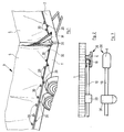
- a tandem axle vehicle trailer is shown in a perspective partial view.
- the box structure consists of side walls 1 and the front wall 2, etc. visible here.
- a frame not shown here, is built, over which a tarpaulin 3 is placed.
- the Tarpaulin 3 forms side walls 4 and the front wall 5 visible here.
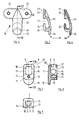
- the rope holder consists of a substantially box-shaped part with an outer cover 7, a narrow wall 8 with a recess 9 for receiving the cross section of the rope 10 and an opposite narrow side 11, which is made of a thicker material, with a Blind hole or a bore 12 may be provided for receiving a fastener.
- the two side walls 13 and 14 can be smoothly continuous, they can also be provided with recesses or openings 15, which are then arranged axially parallel to one another, expediently also with their axes in a plane to the opening 9 and like this for receiving the cross section serve the rope 1o.
- a protrusion 16 is arranged which, seen in plan, has a rounded outer boundary, corresponding to FIG. 7.
- the rope holder (retaining nose) 20 described above is flat on its support surface 17 and has a rectangular opening 18, which is closed on the vehicle wall 1 after it has been attached and fastened.
- the rope holder described above (the retaining nose) 2o serves, according to FIGS. 2 and 3, first of all for the fixed and captive attachment of the elastic rope 1 0 , which is provided with thickenings 19 at its ends.
- the rope After passing through the recess 9, the rope is provided with the thickening 19, or it is already cut to length and provided with the thickening 19 at both ends - then the lower part of the recess 9, which is between this recess and the support surface lies, cut out and the rope inserted from the support surface into the cable holder, so that the thickening 9, three quarters surrounded by the recess, is held in these positions in the cable holder.
- the rope holder 2o is provided with the openings 15 through which the rope can be pulled before it is fixedly attached to the wall 1 and firmly connected to the end rope retaining fittings.
- This connection of the rope 1o with rope holders 2o is used for the non-releasable fastening and connection of the rope on the side wall 1. It can be used advantageously, for example, if the rope is to be led to a different height with a deflection, or if the rope to be led around a corner edge, for example in the event that a rope is to be stretched over a side wall 1 and a front wall 2. With two appropriately arranged rope holders directly on the corner edge between the two walls 1 and 2, the rope is guided around this edge.
- the cable holders 2o are provided with the projection 16 and are attached at desired intervals and positions on the side wall, distributed over their length, at the same distance from the upper edge of the side wall 1, in such a way that these projections 16 point down.
- the rope holders serve as retaining noses for the rope. So only a single fitting part is required, which due to its special shape can be used for a wide variety of purposes.
- hooks 30 are attached in the area of the lower edge of the tarpaulin 4. These hooks are explained in detail with reference to FIGS. 4 to 6: They consist of a base with a support surface 21 and bores 22 for screws or rivets for firmly connecting the hook to the tarpaulin.
- the base can form the crossbar 23 of the T when the hook is T-shaped, as shown in FIG. 4.
- the hook can also be connected to the tarpaulin by welding or gluing.
- the stem 23 extends from the base at an acute angle and is slightly arched, which carries the actual hook 24 at its lower end or merges into it. Outside this hook bend, the handle 23 is extended beyond the hook curvature and provided with a protrusion 25 which, in the top view corresponding to FIG. 4, can be rounded.
- a curvature 26 is formed within the hook curvature, which appropriately corresponds to the curvature of the rope inserted into the hook.
- the insert opening 27 of the hook is located between the base with the support surface 21 and the end of the curvature of the hook 24.
- This insert opening can be bridged by a spring, not shown here, for example, which is attached to the base and rests against the end of the hook curve , so that, similar to a snap hook, a rope inserted in the hook is retained.
- a spring not shown here, for example, which is attached to the base and rests against the end of the hook curve , so that, similar to a snap hook, a rope inserted in the hook is retained.
- the hooks 30 are connected to the tarpaulin with their bearing surface 21, the insert opening 27 immediately below is from the Tarpaulin covered and blocked to a certain extent.
- the hooks 3o are assigned in different ways to the position of the retaining lugs 2o on the tarpaulin. A possible arrangement is shown in FIG. 1.
- a Velcro strap 31 is fastened on one separating side and a velvet loop strap 32 is fastened on the opposite side.
Landscapes
- Engineering & Computer Science (AREA)
- Mechanical Engineering (AREA)
- Refuge Islands, Traffic Blockers, Or Guard Fence (AREA)
- Hooks, Suction Cups, And Attachment By Adhesive Means (AREA)
Applications Claiming Priority (2)
| Application Number | Priority Date | Filing Date | Title |
|---|---|---|---|
| DE19828219362 DE8219362U1 (de) | 1982-07-07 | 1982-07-07 | Strassenfahrzeug mit kastenaufbau und plane |
| DE8219362U | 1982-07-07 |
Publications (3)
| Publication Number | Publication Date |
|---|---|
| EP0098527A2 true EP0098527A2 (fr) | 1984-01-18 |
| EP0098527A3 EP0098527A3 (en) | 1986-05-07 |
| EP0098527B1 EP0098527B1 (fr) | 1988-12-21 |
Family
ID=6741643
Family Applications (1)
| Application Number | Title | Priority Date | Filing Date |
|---|---|---|---|
| EP19830106365 Expired EP0098527B1 (fr) | 1982-07-07 | 1983-06-30 | Véhicule routier du type fourgon bâché |
Country Status (3)
| Country | Link |
|---|---|
| EP (1) | EP0098527B1 (fr) |
| DE (1) | DE8219362U1 (fr) |
| DK (1) | DK160690C (fr) |
Cited By (3)
| Publication number | Priority date | Publication date | Assignee | Title |
|---|---|---|---|---|
| WO1991014593A1 (fr) * | 1990-03-20 | 1991-10-03 | Jens Eriksson Försäljning Ab | Agencement servant a joindre deux parties contigues en toile de la bache d'un vehicule |
| WO1991015351A1 (fr) * | 1990-04-06 | 1991-10-17 | Short Brothers Plc | Systeme d'ensachage pour appareil de traitement de pieces en resine synthetique |
| US6010176A (en) * | 1997-03-18 | 2000-01-04 | Worldwide Container Services, Inc. | Reversible cover for trucks, trailers and other vehicles |
Citations (3)
| Publication number | Priority date | Publication date | Assignee | Title |
|---|---|---|---|---|
| DE835408C (de) * | 1950-12-14 | 1952-03-31 | Greffenius K G Dr | Vorrichtung zur Befestigung der Plane von Wagenkaesten mittels an den Kastenwaenden angebrachter OEsen |
| DE1906881U (de) * | 1964-08-14 | 1964-12-17 | Deuter Ind | Plane fuer lastkraftwagen oder anhaenger. |
| DE7638695U1 (de) * | 1976-12-10 | 1977-05-05 | Otto Mittenzwei Ohg, 5600 Wuppertal | Aufbau mit planen-randkantenverschluss, insbesondere an lkws |
-
1982
- 1982-07-07 DE DE19828219362 patent/DE8219362U1/de not_active Expired
-
1983
- 1983-06-30 EP EP19830106365 patent/EP0098527B1/fr not_active Expired
- 1983-07-05 DK DK309283A patent/DK160690C/da active
Patent Citations (3)
| Publication number | Priority date | Publication date | Assignee | Title |
|---|---|---|---|---|
| DE835408C (de) * | 1950-12-14 | 1952-03-31 | Greffenius K G Dr | Vorrichtung zur Befestigung der Plane von Wagenkaesten mittels an den Kastenwaenden angebrachter OEsen |
| DE1906881U (de) * | 1964-08-14 | 1964-12-17 | Deuter Ind | Plane fuer lastkraftwagen oder anhaenger. |
| DE7638695U1 (de) * | 1976-12-10 | 1977-05-05 | Otto Mittenzwei Ohg, 5600 Wuppertal | Aufbau mit planen-randkantenverschluss, insbesondere an lkws |
Cited By (4)
| Publication number | Priority date | Publication date | Assignee | Title |
|---|---|---|---|---|
| WO1991014593A1 (fr) * | 1990-03-20 | 1991-10-03 | Jens Eriksson Försäljning Ab | Agencement servant a joindre deux parties contigues en toile de la bache d'un vehicule |
| WO1991015351A1 (fr) * | 1990-04-06 | 1991-10-17 | Short Brothers Plc | Systeme d'ensachage pour appareil de traitement de pieces en resine synthetique |
| US6010176A (en) * | 1997-03-18 | 2000-01-04 | Worldwide Container Services, Inc. | Reversible cover for trucks, trailers and other vehicles |
| US6302469B1 (en) | 1997-03-18 | 2001-10-16 | Samuel H. Jones | Reversible cover for trucks, trailers, and other vehicles |
Also Published As
| Publication number | Publication date |
|---|---|
| EP0098527B1 (fr) | 1988-12-21 |
| DK160690C (da) | 1991-09-23 |
| DK309283D0 (da) | 1983-07-05 |
| EP0098527A3 (en) | 1986-05-07 |
| DE8219362U1 (de) | 1982-11-04 |
| DK160690B (da) | 1991-04-08 |
| DK309283A (da) | 1984-01-08 |
Similar Documents
| Publication | Publication Date | Title |
|---|---|---|
| DE4391983B4 (de) | Aufbewahrungsnetz | |
| DE2735382C2 (de) | Abdeckplane für Lastkraftwagen | |
| DE8300286U1 (de) | Ziehgriff | |
| CH669121A5 (de) | Traghilfe fuer ski. | |
| EP0145646B1 (fr) | Dispositif de liaison de membres, de dispositifs tendeurs et/ou de contrôle avec des sangles | |
| EP0389831B1 (fr) | Dispositif pour ligaturer des éléments allongés | |
| DE202011052068U1 (de) | Transportsicherungsvorrichtung | |
| DE112004001361T5 (de) | Sicherheitsgurtspange | |
| EP0098527A2 (fr) | Véhicule routier du type fourgon bâché | |
| DE102017001817A1 (de) | Verzurrsystem zum Sichern von Ladung in einem Container | |
| DE3823456C1 (en) | Floor-wiping implement | |
| DE102019101047B4 (de) | Nutzfahrzeugaufbau und Nutzfahrzeug mit einem derartigen Nutzfahrzeugaufbau | |
| DE10056699B4 (de) | Flexible Seitenwand für einen Fahrzeugaufbau | |
| EP1123838A2 (fr) | Dispositif d'amarrage, notamment pour un espace de chargement de véhicule automobile | |
| DE2810481C2 (de) | Einrichtung zum Spannen von Planen | |
| DE8223834U1 (de) | Sitzgelegenheit | |
| DE102011117441A1 (de) | Vorrichtung zur Halterung von wenigstens einem Transportsicherungsnetz, in einem Fahrzeug | |
| EP0911192B1 (fr) | Elément de fermeture de la chaíne de serrage d'une chaíne anti-dérapante | |
| DE202006007993U1 (de) | Verzurrhaken und System zum Verzurren von Lasten auf der Ladefläche eines Fahrzeugs sowie Fahrzeug zum Transport einer Last | |
| DE202007005993U1 (de) | Flächiges Sicherungsmittel | |
| DE2354583B2 (de) | Vorrichtung zum verbinden von persenningen | |
| DE102004034586A1 (de) | Fahrzeug mit Ladeboden | |
| EP3069929A1 (fr) | Châssis de véhicule pour remorques de véhicule | |
| DE7834381U1 (de) | Netz zum Verzurren von Lasten auf Ladeflächen von Fahrzeugen | |
| EP1361111A2 (fr) | Support pour sangle de serrage |
Legal Events
| Date | Code | Title | Description |
|---|---|---|---|
| PUAI | Public reference made under article 153(3) epc to a published international application that has entered the european phase |
Free format text: ORIGINAL CODE: 0009012 |
|
| AK | Designated contracting states |
Designated state(s): FR GB IT NL |
|
| 17P | Request for examination filed |
Effective date: 19840306 |
|
| PUAL | Search report despatched |
Free format text: ORIGINAL CODE: 0009013 |
|
| AK | Designated contracting states |
Kind code of ref document: A3 Designated state(s): FR GB IT NL |
|
| 17Q | First examination report despatched |
Effective date: 19870728 |
|
| GRAA | (expected) grant |
Free format text: ORIGINAL CODE: 0009210 |
|
| AK | Designated contracting states |
Kind code of ref document: B1 Designated state(s): FR GB IT NL |
|
| GBT | Gb: translation of ep patent filed (gb section 77(6)(a)/1977) | ||
| ITF | It: translation for a ep patent filed |
Owner name: STUDIO JAUMANN |
|
| ET | Fr: translation filed | ||
| PLBE | No opposition filed within time limit |
Free format text: ORIGINAL CODE: 0009261 |
|
| STAA | Information on the status of an ep patent application or granted ep patent |
Free format text: STATUS: NO OPPOSITION FILED WITHIN TIME LIMIT |
|
| 26N | No opposition filed | ||
| ITTA | It: last paid annual fee | ||
| PGFP | Annual fee paid to national office [announced via postgrant information from national office to epo] |
Ref country code: GB Payment date: 19910722 Year of fee payment: 9 |
|
| PG25 | Lapsed in a contracting state [announced via postgrant information from national office to epo] |
Ref country code: GB Effective date: 19920630 |
|
| GBPC | Gb: european patent ceased through non-payment of renewal fee |
Effective date: 19920630 |
|
| PGFP | Annual fee paid to national office [announced via postgrant information from national office to epo] |
Ref country code: FR Payment date: 19930629 Year of fee payment: 11 |
|
| PGFP | Annual fee paid to national office [announced via postgrant information from national office to epo] |
Ref country code: NL Payment date: 19930630 Year of fee payment: 11 |
|
| PG25 | Lapsed in a contracting state [announced via postgrant information from national office to epo] |
Ref country code: NL Effective date: 19950101 |
|
| NLV4 | Nl: lapsed or anulled due to non-payment of the annual fee | ||
| PG25 | Lapsed in a contracting state [announced via postgrant information from national office to epo] |
Ref country code: FR Effective date: 19950228 |
|
| REG | Reference to a national code |
Ref country code: FR Ref legal event code: ST |