EP0091589A2 - Gerät zum Regeln eines Induktionsmotors - Google Patents
Gerät zum Regeln eines Induktionsmotors Download PDFInfo
- Publication number
- EP0091589A2 EP0091589A2 EP83102944A EP83102944A EP0091589A2 EP 0091589 A2 EP0091589 A2 EP 0091589A2 EP 83102944 A EP83102944 A EP 83102944A EP 83102944 A EP83102944 A EP 83102944A EP 0091589 A2 EP0091589 A2 EP 0091589A2
- Authority
- EP
- European Patent Office
- Prior art keywords
- stator
- rotor
- motor
- slip
- frequency
- Prior art date
- Legal status (The legal status is an assumption and is not a legal conclusion. Google has not performed a legal analysis and makes no representation as to the accuracy of the status listed.)
- Withdrawn
Links
Images


Classifications
-
- H—ELECTRICITY
- H02—GENERATION; CONVERSION OR DISTRIBUTION OF ELECTRIC POWER
- H02P—CONTROL OR REGULATION OF ELECTRIC MOTORS, ELECTRIC GENERATORS OR DYNAMO-ELECTRIC CONVERTERS; CONTROLLING TRANSFORMERS, REACTORS OR CHOKE COILS
- H02P21/00—Arrangements or methods for the control of electric machines by vector control, e.g. by control of field orientation
- H02P21/06—Rotor flux based control involving the use of rotor position or rotor speed sensors
- H02P21/10—Direct field-oriented control; Rotor flux feed-back control
-
- H—ELECTRICITY
- H02—GENERATION; CONVERSION OR DISTRIBUTION OF ELECTRIC POWER
- H02P—CONTROL OR REGULATION OF ELECTRIC MOTORS, ELECTRIC GENERATORS OR DYNAMO-ELECTRIC CONVERTERS; CONTROLLING TRANSFORMERS, REACTORS OR CHOKE COILS
- H02P21/00—Arrangements or methods for the control of electric machines by vector control, e.g. by control of field orientation
- H02P21/22—Current control, e.g. using a current control loop
Definitions
- the invention's objective is a process for regulating an asynchronous motor which is energized by fast-acting control or corection elements such as, for example, voltage-impressing pulsed dc/ac converters (or inverters) transistorized dc/ac inverters, current-impressing intermediate (link) circuit inverters, etc.
- fast-acting control or corection elements such as, for example, voltage-impressing pulsed dc/ac converters (or inverters) transistorized dc/ac inverters, current-impressing intermediate (link) circuit inverters, etc.
- the supplementary accessories consisting of tachometers, rotor-position sensors and also, if need be, devices for carrying out a direct measurement of the field, are very undesirable complications, but they are, however, unavoidable if it is desired to effect control over a large rotational speed range, including crawling rotational speeds, with good dynamics.
- problems arise due to the required integration of measured variables without feedback.
- the range encompassing the crawling rotational speeds must be excluded. Also troublesome is that initial conditions are necessary in carrying out an integration.
- the stator frequency is formed as the sum of the frequency of rotor rotation and a limited slip frequency which is specified by the rotational-speed regulating device, and the slip frequency is allocated to the value of the required current via a characteristic curve former.
- a superimposed voltage regulating circuit whose actual value forms the rectified motor voltage.
- the required value of the voltage and the input data for the stator frequency are allotted to each other in accordance with a fixed characteristic curve.
- the two-last-named processes and arrangements are mentioned as an example for the group of applications in which, with regard to the simplicity of the signal processing and low expenditure for sensors, allowance must be made for rise times of the order of 500 ms and poor damping of the transient effects.
- the invention's objective is to fill the gap between complex devices which are expensive as far as the sensors to obtain good dynamic behavior are concerned and the applications with low costs for sensors, with poor dynamic behavior, and to create a regulating system which makes do solely with measurements of the current and the voltage and which, at the same time, provides satisfactory dynamic behavior, sufficient static accuracy in the regulation and a large range of rotational speed control.
- a regulating system which makes do solely with measurements of the current and the voltage and which, at the same time, provides satisfactory dynamic behavior, sufficient static accuracy in the regulation and a large range of rotational speed control.
- the torque it should also be possible to control the torque as is required, for example, in spooling drive systems.
- the invention concerns a process and an apparatus for regulating an asynchronous motor which is energized by fast-acting control elements such as, for example, thyristorized or transistorized inverters, using terminal currents and terminal voltages as the important measured quantities (process variables) for the regulation.
- fast-acting control elements such as, for example, thyristorized or transistorized inverters
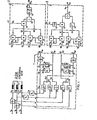
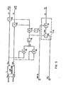
- rotor emf components e 2a and e 2 ⁇ are formed from two terminal currents and two terminal voltages in a computer circuit(l), shown in Fig. 1, on the basis of the equations where e 2a and e 2 ⁇ represent the rotational emf induced in the rotor winding in an orthogonal (a,8)-reference system fixed in the stator.
- Quantities with the indices ( ⁇ , ⁇ ) are here, and in the following, quantities such as, for example, i l ⁇ and i l ⁇ , in an orthogonal reference system fixed in a stator.
- the pair of components represents vectors in space.
- Vectors are also symbolically written as underlined quantities.
- a computed value w 2c is formed in (2) in Fig. 1 for the instantaneous value of the slip frequency in accordance with Fig. 1, based on the equation
- This sub-assembly (2) will also be designated in the following as the slip calculator.
- i lxc for a stator current component which is proportional to the slip frequency and which is termed the i ix component in the following, the value of i lxc being obtained from the equation produced in (3) in Fig. 1.
- This sub-assembly will also be designated as an i lx -calculator.
- stator resistance R 1 stator inductance L 1
- main inductance M main inductance M.
- L 2 denotes the rotor inductance referred to the stator side
- R 11 L 2 /(L 1 L 2 - M 2 ) as is usual in the two-axis theory of the motor.
- the representation carried out in References (1) and (2) are used as a basis, that is, the impedance parameters are 2/3 of the phase values.
- Two current transformers (7, 8) and two voltage transformers (9, 10) form the potential-free measurement data for the stator voltages and currents.
- the differentiations in (1) Fig. 1 (34, 39) can be formed via pure differentiating circuits, but also via differentiating circuits with subsequent delay of the first order.
- Multiplication with signum wI (71) in Fig. 1 can also be effected in known manner without a multiplier unit using an operational amplifier in conjunction with an analog circuit and a comparator.
- the components of the rotor emf are determined in a stator-fixed orthogonal reference system from terminal currents and terminal voltages.
- the necessary computational operations, scaling, adding, subtracting, multiplying and dividing can all be easily effected with commercially common analog computers, likewise the double differentiation.
- a further surprising advantage resides in the fact that the values for the rotor emf, although containing the first derivative of the stater current components as a constituent, are quantities with very low harmonics content. Whereas, in general, a smoothing is expected from an integration and, on the other hand, an increase is expected in the harmonics fraction as the result of a differentiation, here the reverse is actually the case based on the structure of the motor.
- an orientation can now be effected on the rotor emf.
- the space vector of the rotor emf is rotated by + ⁇ /2 or - ⁇ /2 with respect to the rotor interlinking flux vector ( ⁇ 2 )and that
- ⁇ 2 applies for the amounts.
- the rotor flux vector always lies in the y direction, while the rotor emf vector lies in the ⁇ x direction of the (x,y) coordinate system.
- the described computer arrangement shown in Fig. 1 can only be employed with the use of a voltage-impressing inverter or with the use of a current impressing inverter in a different way.
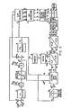
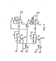
- a subordinate slip regulating circuit which receives its required slip value ⁇ from a superimposed regulator such as, for example, a rotational speed regulating device, a torque input value or, as shown, from a stator frequency regulator (80 to 86).
- a superimposed regulator such as, for example, a rotational speed regulating device, a torque input value or, as shown, from a stator frequency regulator (80 to 86).
- the output value of the slip frequency calculator is the actual value fed to the ⁇ 2 regulator (89), the stator frequency is the output quantity.
- the stator frequency, the required value of the rotor frequency and the input value for the value of the rotor interlinking flux are used to build the required voltage components (u x , u y) in the direction of the rotor interlinking flux and at right angles to it (93).
- the slip-frequency limitation is arrived at by providing a limiter (85) in known manner for the required value of the slip.
- the internal slip- regulating circuit was not possible until now, because it was lacking an accurate, dynamically correct measuring possibility.
- PWM pulse width modulation process
- PWR pulse dc/ac inverter.
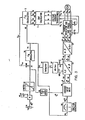
- a subordinated regulating circuit is provided for the stator current component i lx , whereby the required value, shown as an example, is formed from a torque input data (110) or from a rotational speed regulating device or from a stator frequency regulator.
- the output from the i lx calculator is the required value i lxc fed to the i lx -regulator (115), the stator frequency is the output quantity.
- the further refinement is very similar to that in Fig. 2.
- the required value of the current producing the torque and the input data for the value of the rotor interlinking flux are used to determine the input data for the current components i x and i y (119), whereby i* 1x is formed directly from the required value of the i lx -regulator via a phase-shifting section (or lag element) of the first order whose time constant is dependent on the i lx regulating circuit.
- slip limitation is attained by limiting the required value of the current component producing the torque (112).
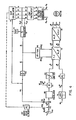
- the angle v 1 can be obtained directly from the rotor emf components.
- v 1 can be computed directly from the arctan of the quotient e 2 ⁇ / e 2 ⁇ or from arccos e 2a
- Fig. 4 shows a signal processor which uses a determination of this type of the angle v from the rotor emf components.
- the current components i x and i y are thereby spatially oriented directly to the rotor emf components.
- the emf calculator shown in Fig. 1 yields the rotor emf components.
- the determination of the angle in the v 1 -calculator (150) is effected as described above.
- the determination of the current components i x and i y along with the two transformations, are already known from the preceding operating examples.
- the formation of the actual value of the stator frequency ⁇ 1 from the differentiation of the angle v 1 (145) is masked out with the passage of the value of the angle 2 ⁇ to 0 (or 0 to 2 ⁇ with w I ⁇ 0), and the last value w 1 is briefly retained.
- Fig. 5 illustrates a solution for the direct formation of the pair of values cos v 1 and sin ⁇ 1 from the components of the rotor emf.
- the value of the rotor emf vector is formed via the two multipliers (160, 161), the summation unit (162) and the unit for forming the square root (163).
- the division (165, 166) of the components of the rotor emf by the value directly yields the calculated values cos ⁇ 1 , sin ⁇ 1 .
- stator frequency to effect a stator frequency regulation
- the sign of the stator frequency (signum ⁇ 1 ) must be known in order to determine the pair of values sin ⁇ 1 and cos ⁇ 1 and the input data for the stator frequency.
- the sign of the stator frequency may easily be determined from the control procedure to be described below.
- Fig. 6 shows a signal processor for an inverter with current- impression in the intermediate circuit using the components of the rotor emf supplied by the emf calculator, and using the direct spatial assignment of the phase current to the rotor emf vector.
- the angle and the value are given separately.
- the angle which determines the conductive state of the dc/ac converter (203) on the motor-side is formed from the angle v 1 and a supplementary angle v which gives the rotation of the stator current required value vector with respect to the rotor emf vector.
- the determination of the value of the intermediate circuit current is derived, on the other hand, in known manner from the magnetization current component and the torque-building current component which is given by the regulator belonging to the external regulator circuit.
- PD (189) denotes a phase-lead element with a proportional part and a differentiating part. Apart from the commutating intervals, only two phase conductors of the motor carry the current and the stator current's space vector consequently carries out an unsteady jerky rotational movement.
- the conduction state is set by the firing pulse input data.
- the rotor emf components need only be known outside the commutation time, it is possible, with the aid of a coordinate transformation from polar into Cartesian coordinates, to determine the instantaneous value of the stator current, in accordance with the invention, from the intermediate dc current as a measure of the value of the stator current space vector, and from the conducting state of the dc/ac converter on the motor side, as a measure of the spatial argument angle.
- the current is and fed as described above to the rotor emf to the slip calculator. It is consequently possible to dispense with two current transformers and the transformation of the actual values of the current from the (a, b, c) into the ( ⁇ , ⁇ ) system of coordinates.
- Fig. 7 illustrates the described simulation (balancing) of the motor's terminal currents from the intermediate circuit current and the conducting state of the dc/ac converter on the motor side, in an arrangement with analog and digital components.
- i zk is the intermediate circuit current which is measured by means of a current transformer and which is used here both for regulating the rectifier on the power supply side and also the value signal for the stator current.
- the logic signals T are determined from the conductive state of the motor-side rectifiers and always have the logic "H" when the associated rectifier conducts.
- the first index of the logic signal indicates the phase conductor with which the assigned rectifier diode is connected
- the second index is equal to 1 for the rectifier diode connected to the cathode side and equal to 2 for the rectifier diode connected to the anode side of the power supply side-rectifier.
- Regulation of the asynchronous motor can be effected with torque input data as, for example, with the arrangement shown by way of example in Fig. 3 or with superimposed regulation of the stator frequency as, for example, in Fig. 2, or with increased requirements with respect to the independence of the rotational speed on the load torque by using a rotational speed controller.
- a required value (n p ⁇ m )* which is proportional to the desired rotational speed.
- To this signal is added the computed value of the slip, the addition being made via a first order delay element (141, 181).
- the value of the sum is fed as a required value to the stator frequency regulating circuit.
- the further developed form of the regulator is as described in the preceding examples.
- Fig. 8 shows a supplementary apparatus which makes possible a frequency-controlled passage through a zone close to the zero-passage of the stator frequency.
- the slip regulator is masked out on undershooting a frequency value a ⁇ 1N , in that a switch-over takes place to the lower path (218, 219).
- Fig. 9 shows an i lx regulator and PI-behavior is assumed for the regulator of the subordinate circuit.
- the required value w of the slip frequency becomes such that the stator frequency is greater than the frequency limit a ⁇ 1N of the control range and that, as a result, the control range can be immediately left on starting.
- regulated operation of the asynchronous motor can be achieved in almost all operating cases which can occur without it being necessary to have an accurate knowledge of the motor's parameters.
- u x , u y, or i x i y must be incorporated both in the input data and in the superimposed regulating circuit.
- the required value of the slip is multiplied in two places, before and after the limiting element (85), by the reciprocal of the field-weakening ratio.
- the required value signal or the input value i x in accordance with Figs. 3, 4 or 6 only one multiplication is carried out, namely before the limiting stage (112, 147, 187).
- the input value for the rotor interlinking flux is modified in a frequency- dependent manner via the characteristic curve diagrams, such as (92) in Fig. 2 or (118) in Fig. 3, and serves as an input quantity for forming the u-input value (93) or the i-input value (119).
- the change in the rotor flux input data value in the field-weakening region has a negligibly small effect on the required condition d
Landscapes
- Engineering & Computer Science (AREA)
- Power Engineering (AREA)
- Control Of Ac Motors In General (AREA)
Applications Claiming Priority (2)
| Application Number | Priority Date | Filing Date | Title |
|---|---|---|---|
| DE3212439A DE3212439C2 (de) | 1982-04-02 | 1982-04-02 | Verfahren zum Betrieb einer durch schnelle elektrische Stellglieder gespeisten Asynchronmaschine |
| DE3212439 | 1982-04-02 |
Publications (2)
| Publication Number | Publication Date |
|---|---|
| EP0091589A2 true EP0091589A2 (de) | 1983-10-19 |
| EP0091589A3 EP0091589A3 (de) | 1985-08-07 |
Family
ID=6160155
Family Applications (1)
| Application Number | Title | Priority Date | Filing Date |
|---|---|---|---|
| EP83102944A Withdrawn EP0091589A3 (de) | 1982-04-02 | 1983-03-24 | Gerät zum Regeln eines Induktionsmotors |
Country Status (5)
| Country | Link |
|---|---|
| US (1) | US4484128A (de) |
| EP (1) | EP0091589A3 (de) |
| JP (1) | JPS58186399A (de) |
| CA (1) | CA1198156A (de) |
| DE (1) | DE3212439C2 (de) |
Cited By (5)
| Publication number | Priority date | Publication date | Assignee | Title |
|---|---|---|---|---|
| GB2190805A (en) * | 1986-05-09 | 1987-11-25 | Hitachi Ltd | Adaptive vector control system |
| US5832019A (en) * | 1994-11-28 | 1998-11-03 | Xerox Corporation | Index guided semiconductor laser biode with shallow selective IILD |
| RU2317632C1 (ru) * | 2006-09-21 | 2008-02-20 | Государственное образовательное учреждение высшего профессионального образования "Ульяновский государственный технический университет" | Система векторного управления скоростью асинхронного электродвигателя |
| RU2320075C1 (ru) * | 2006-07-05 | 2008-03-20 | Открытое акционерное общество "Рудоавтоматика" | Способ настройки ir-компенсации в системах управления электроприводов переменного тока по косвенно определенному потокосцеплению статора |
| RU2379821C1 (ru) * | 2005-10-27 | 2010-01-20 | Тойота Дзидося Кабусики Кайся | Система электропривода |
Families Citing this family (35)
| Publication number | Priority date | Publication date | Assignee | Title |
|---|---|---|---|---|
| DE3411572C2 (de) * | 1984-03-29 | 1986-12-04 | Joetten, Robert, Prof.Dr.-Ing., 6100 Darmstadt | Verfahren zur Regelung einer durch einen stromeinprägenden Zwischenkreisumrichter gespeisten Asynchronmaschine |
| US4958116A (en) * | 1984-06-18 | 1990-09-18 | Mitsubishi Denki Kabushiki Kaisha | Method for controlling AC induction motor |
| US4680515A (en) * | 1985-05-21 | 1987-07-14 | Crook James C | Digital speed control of motors |
| US4672288A (en) * | 1985-06-18 | 1987-06-09 | Westinghouse Electric Corp. | Torque controller for an AC motor drive and AC motor drive embodying the same |
| JPH0793839B2 (ja) * | 1985-07-25 | 1995-10-09 | 三菱電機株式会社 | 誘導電動機の制御装置 |
| GB8603800D0 (en) * | 1986-02-15 | 1986-03-19 | Brown J E | Vector control system |
| US4677360A (en) * | 1986-03-13 | 1987-06-30 | General Electric Company | Field weakening induction drive |
| DE3820125C2 (de) * | 1987-06-12 | 1994-04-07 | Hitachi Ltd | Verfahren zum Steuern eines wechselrichtergespeisten Asynchronmotors |
| JPH07108119B2 (ja) * | 1987-08-08 | 1995-11-15 | 三菱電機株式会社 | 誘導電動機制御装置 |
| US4885518A (en) * | 1987-08-21 | 1989-12-05 | Westinghouse Electric Corp. | Induction motor torque/flux control system |
| JPH0751000B2 (ja) * | 1988-02-01 | 1995-05-31 | 富士電機株式会社 | 誘導電動機の可変速制御装置 |
| JP2780263B2 (ja) * | 1988-02-23 | 1998-07-30 | 株式会社明電舎 | 誘導電動機のベクトル制御方法と装置 |
| US5296794A (en) * | 1988-10-28 | 1994-03-22 | Massachusetts Institute Of Technology | State observer for the permanent-magnet synchronous motor |
| EP0500121B1 (de) * | 1991-02-22 | 1996-11-27 | Mitsubishi Denki Kabushiki Kaisha | Steuervorrichtung für einen Asynchronmotor |
| US5440219A (en) * | 1993-05-21 | 1995-08-08 | Wilkerson; Alan W. | Induction motor speed control having improved sensing of motor operative conditions |
| US5362222A (en) * | 1993-08-31 | 1994-11-08 | Cincinnati Milacron Inc. | Injection molding machine having a vector controlled AC drive system |
| US5541488A (en) * | 1994-04-11 | 1996-07-30 | Sundstrand Corporation | Method and apparatus for controlling induction motors |
| US5844397A (en) * | 1994-04-29 | 1998-12-01 | Reda Pump | Downhole pumping system with variable speed pulse width modulated inverter coupled to electrical motor via non-gap transformer |
| DE59401808D1 (de) * | 1994-06-30 | 1997-03-27 | Siemens Ag | Stillstandserkennung beim Wiederanlassen eines stromrichtergespeisten Drehstrommotors ohne Drehzahlgeber |
| FR2746982B1 (fr) * | 1996-03-28 | 1998-05-07 | Schneider Electric Sa | Convertisseur de frequence pour moteur alternatif |
| DE19612920A1 (de) * | 1996-04-01 | 1997-10-02 | Asea Brown Boveri | Verfahren und Vorrichtung zur direkten Drehmomentregelung einer Drehfeldmaschine |
| US5909098A (en) * | 1996-05-02 | 1999-06-01 | Reda Pump | Downhole pumping system with variable speed pulse-width modulated inverter coupled to electrical motor via non-gap transformer |
| FR2759216B1 (fr) * | 1997-02-06 | 1999-03-05 | Alsthom Cge Alcatel | Procede de regulation d'une machine tournante, systeme d'asservissement pour mettre en oeuvre ledit procede, et machine tournante pourvue d'un tel systeme |
| CN100438320C (zh) * | 1997-10-31 | 2008-11-26 | 株式会社日立制作所 | 电源转换设备 |
| US6046554A (en) * | 1998-02-13 | 2000-04-04 | General Electric Company | Method and apparatus for calibrating a permanent-magnet motor using back EMF measurement |
| RU2158055C2 (ru) * | 1998-06-02 | 2000-10-20 | Ульяновский государственный технический университет | Система векторного управления скоростью асинхронного электропривода |
| JP3815113B2 (ja) * | 1999-04-23 | 2006-08-30 | 株式会社日立製作所 | 誘導電動機の制御方法 |
| FR2818826B1 (fr) * | 2000-12-27 | 2003-02-07 | Schneider Electric Ind Sa | Systeme de limitation du courant en sortie d'un variateur de vitesse |
| NL1020601C2 (nl) * | 2002-05-15 | 2003-11-27 | Gti Electroproject B V | Werkwijze en inrichting voor het sturen van een elektrische belasting aangesloten op een meerfasen schakelbare DC/AC-frequentie-omzetter. |
| RU2231203C2 (ru) * | 2002-07-30 | 2004-06-20 | Государственное образовательное учреждение высшего профессионального образования Московский энергетический институт (технический университет) | Трехфазный непосредственный преобразователь частоты для асинхронного электропривода |
| DE102008025408B4 (de) * | 2008-05-27 | 2024-06-20 | Sew-Eurodrive Gmbh & Co Kg | Steuer- oder Regelverfahren für einen Umrichter |
| WO2011085805A1 (de) * | 2010-01-12 | 2011-07-21 | Mk-Regler Gmbh | Verfahren und vorrichtung zum betreiben eines asynchronmotors mit gesteigerter effizienz |
| EP2421145B1 (de) * | 2010-08-16 | 2015-02-11 | Baumüller Nürnberg GmbH | Vorrichtung und Verfahren zur drehgeberlosen Identifikation elektrischer Ersatzschaltbildparameter eines Drehstrom-Asynchronmotors |
| US9705438B2 (en) | 2015-07-14 | 2017-07-11 | Infineon Technologies Austria Ag | Controller for a free-running motor |
| GB2574645B (en) * | 2018-06-14 | 2020-07-15 | Zhong Qingchang | Passive virtual synchronous machine with bounded frequency and virtual flux |
Family Cites Families (12)
| Publication number | Priority date | Publication date | Assignee | Title |
|---|---|---|---|---|
| DE1250914B (de) * | 1967-09-28 | Licentia Patent-Verwaltungs G m b H , Frankfurt/M | Drehzahlsteuerung eines Dreiphasenasynchronmotors | |
| US3824437A (en) * | 1969-08-14 | 1974-07-16 | Siemens Ag | Method for controlling asynchronous machines |
| US3671831A (en) * | 1971-03-05 | 1972-06-20 | Gen Electric | Induction motor speed control |
| US3989991A (en) * | 1974-10-03 | 1976-11-02 | Westinghouse Electric Corporation | Method and circuit for the derivation of an analog slip frequency signal of an induction motor in a tachometerless motor drive |
| JPS5160428A (de) * | 1974-11-25 | 1976-05-26 | Hitachi Ltd | |
| DE2635965C3 (de) * | 1976-08-10 | 1979-01-18 | Siemens Ag, 1000 Berlin Und 8000 Muenchen | Schaltungsanordnung und Verfahren zur Bildung einer elektrischen Größe, die einer Flußkomponente in einer Drehfeldmaschine proportional ist |
| JPS5463634A (en) * | 1977-10-03 | 1979-05-22 | Nec Corp | Bus controller |
| DE2919852A1 (de) * | 1979-05-16 | 1980-12-04 | Siemens Ag | Lastzustandsregelung einer umrichtergespeisten asynchronmaschine |
| JPS56164428A (en) * | 1980-05-20 | 1981-12-17 | Nippon Telegr & Teleph Corp <Ntt> | Data transfer controlling system |
| DE3026202A1 (de) * | 1980-07-10 | 1982-02-04 | Siemens AG, 1000 Berlin und 8000 München | Drehfeldmaschinenantrieb mit einer umrichtergespeisten drehfeldmaschine und einer mit zwei wechselspannungsintegratoren und einer rechenmodellschaltung verbundenen umrichtersteuerung |
| DE3034252A1 (de) * | 1980-09-11 | 1982-04-15 | Siemens AG, 1000 Berlin und 8000 München | Vorrichtung zum feldorientierten betrieb einer umrichtergespeisten asynchronmaschine |
| US4418308A (en) * | 1982-08-09 | 1983-11-29 | General Electric Company | Scalar decoupled control for an induction machine |
-
1982
- 1982-04-02 DE DE3212439A patent/DE3212439C2/de not_active Expired - Lifetime
-
1983
- 1983-03-24 EP EP83102944A patent/EP0091589A3/de not_active Withdrawn
- 1983-03-30 CA CA000424945A patent/CA1198156A/en not_active Expired
- 1983-03-30 US US06/480,194 patent/US4484128A/en not_active Expired - Fee Related
- 1983-04-01 JP JP58058569A patent/JPS58186399A/ja active Pending
Cited By (7)
| Publication number | Priority date | Publication date | Assignee | Title |
|---|---|---|---|---|
| GB2190805A (en) * | 1986-05-09 | 1987-11-25 | Hitachi Ltd | Adaptive vector control system |
| GB2190805B (en) * | 1986-05-09 | 1990-07-11 | Hitachi Ltd | A control apparatus for an inverter with self-adjustment function of control constants |
| US5832019A (en) * | 1994-11-28 | 1998-11-03 | Xerox Corporation | Index guided semiconductor laser biode with shallow selective IILD |
| RU2379821C1 (ru) * | 2005-10-27 | 2010-01-20 | Тойота Дзидося Кабусики Кайся | Система электропривода |
| US7893637B2 (en) | 2005-10-27 | 2011-02-22 | Toyota Jidosha Kabushiki Kaisha | Motor drive system |
| RU2320075C1 (ru) * | 2006-07-05 | 2008-03-20 | Открытое акционерное общество "Рудоавтоматика" | Способ настройки ir-компенсации в системах управления электроприводов переменного тока по косвенно определенному потокосцеплению статора |
| RU2317632C1 (ru) * | 2006-09-21 | 2008-02-20 | Государственное образовательное учреждение высшего профессионального образования "Ульяновский государственный технический университет" | Система векторного управления скоростью асинхронного электродвигателя |
Also Published As
| Publication number | Publication date |
|---|---|
| JPS58186399A (ja) | 1983-10-31 |
| US4484128A (en) | 1984-11-20 |
| DE3212439A1 (de) | 1983-10-13 |
| EP0091589A3 (de) | 1985-08-07 |
| CA1198156A (en) | 1985-12-17 |
| DE3212439C2 (de) | 1992-02-20 |
Similar Documents
| Publication | Publication Date | Title |
|---|---|---|
| EP0091589A2 (de) | Gerät zum Regeln eines Induktionsmotors | |
| EP0629038B1 (de) | Wechselstrommotorregelung | |
| US4862343A (en) | Induction motor control apparatus | |
| US4041361A (en) | Constant torque induction motor drive system | |
| EP0330188B1 (de) | Flussvektorregelung für einen Asynchronmotor | |
| EP0082303B1 (de) | Verfahren und Vorrichtung zum Steuern eines Induktionsmotors | |
| EP0490024B1 (de) | Vektorsteuerung | |
| JP2580101B2 (ja) | 誘導電動機制御システムの制御演算定数設定方法 | |
| JP3070391B2 (ja) | 誘導電動機のベクトル制御装置 | |
| US5734251A (en) | Control apparatus for AC motor | |
| JPH0773438B2 (ja) | 誘導電動機の可変速制御装置 | |
| US4475074A (en) | Apparatus for determining the common frequency of two independently variable electrical a-c variables, especially in a rotating-field machine | |
| JP2856564B2 (ja) | 同期電動機の制御装置 | |
| JPH06335278A (ja) | 誘導電動機のベクトル制御インバータのチューニング方法 | |
| JPH0344509B2 (de) | ||
| JPS6159071B2 (de) | ||
| JP2634959B2 (ja) | 速度センサレス速度制御方式 | |
| JPS6146189A (ja) | 誘導電動機の制御装置 | |
| JP3124019B2 (ja) | 誘導電動機の制御装置 | |
| JP3118940B2 (ja) | 誘導電動機のベクトル制御装置 | |
| EP0427571B1 (de) | Wechselstrommotorregelung | |
| JPH01198292A (ja) | 誘導電動機の可変速制御装置 | |
| SU904178A1 (ru) | Устройство дл управлени асинхронизированной синхронной машиной | |
| SU987771A1 (ru) | Устройство дл управлени магнитным потоком асинхронной машины | |
| JPH0561876B2 (de) |
Legal Events
| Date | Code | Title | Description |
|---|---|---|---|
| PUAI | Public reference made under article 153(3) epc to a published international application that has entered the european phase |
Free format text: ORIGINAL CODE: 0009012 |
|
| AK | Designated contracting states |
Designated state(s): BE FR GB IT |
|
| PUAL | Search report despatched |
Free format text: ORIGINAL CODE: 0009013 |
|
| AK | Designated contracting states |
Designated state(s): BE FR GB IT |
|
| 17P | Request for examination filed |
Effective date: 19850930 |
|
| 17Q | First examination report despatched |
Effective date: 19860702 |
|
| D17Q | First examination report despatched (deleted) | ||
| STAA | Information on the status of an ep patent application or granted ep patent |
Free format text: STATUS: THE APPLICATION IS DEEMED TO BE WITHDRAWN |
|
| 18D | Application deemed to be withdrawn |
Effective date: 19900324 |
|
| RIN1 | Information on inventor provided before grant (corrected) |
Inventor name: JOETTEN, ROBERT HEINRICH, PROF. DR. Inventor name: MAEDER, UDO GERHARD, DR. ING. |