-
The invention's objective is a process for regulating an asynchronous motor which is energized by fast-acting control or corection elements such as, for example, voltage-impressing pulsed dc/ac converters (or inverters) transistorized dc/ac inverters, current-impressing intermediate (link) circuit inverters, etc. The state of development in this field is described, for example, in the survey articles (1) and (2) of the references to the recent literature in the present application and in the additional references. Further, the invention is concerned with the rotational speed or torque regulation of asynchronous motors, chiefly those with squirrel cage rotors.
-
The state of the art reveals two lines of development. The dynamic behavior of the motors is today so well investigated that it is possible, with the inverters now available, to construct control and regulating devices which are equivalent or even superior in their dynamic behavior to rectifier energized dc motors. These arrangements require either a measurement of the rotor's position, in which case an additional automatic matching of the regulator to the rotor resistance, which varies with temperature, is required, or a measurement of the field is necessary. Further, the regulation must be carried out mainly as a regulation of the rotational speed, in which case, it is necessary to employ a tachometer motor. The supplementary accessories consisting of tachometers, rotor-position sensors and also, if need be, devices for carrying out a direct measurement of the field, are very undesirable complications, but they are, however, unavoidable if it is desired to effect control over a large rotational speed range, including crawling rotational speeds, with good dynamics. When, instead of field- measuring, use is made of field simulation , problems arise due to the required integration of measured variables without feedback. In addition, the range encompassing the crawling rotational speeds must be excluded. Also troublesome is that initial conditions are necessary in carrying out an integration.
-
Of course, the majority of applications requires the adjustability of the rotational speed, and the requirements with regard to the dynamic behavior, that is control rate, and with respect to the static accuracy and load-independence of the set rotational speed,are comparatively small. Regulating devices for the stator frequency as a main control variable, or the rotational speed as a main control variable, are known for these cases. The regulation is mainly effected with current-impressed inverters. In the process, the intermediate circuit-current, as a substitute for the value of the stator current, is regulated in a subordinate circuit. In the case of speed control, the stator frequency is formed as the sum of the frequency of rotor rotation and a limited slip frequency which is specified by the rotational-speed regulating device, and the slip frequency is allocated to the value of the required current via a characteristic curve former. In a known setup with no tachometer, there is added to the current controller a superimposed voltage regulating circuit whose actual value forms the rectified motor voltage. The required value of the voltage and the input data for the stator frequency are allotted to each other in accordance with a fixed characteristic curve. In the main, there is no slip limitation with this special arrangement. Overshooting the breakdown (stalling) slip is prevented by limiting the speed of rotation. The two-last-named processes and arrangements are mentioned as an example for the group of applications in which, with regard to the simplicity of the signal processing and low expenditure for sensors, allowance must be made for rise times of the order of 500 ms and poor damping of the transient effects.
-
The invention's objective is to fill the gap between complex devices which are expensive as far as the sensors to obtain good dynamic behavior are concerned and the applications with low costs for sensors, with poor dynamic behavior, and to create a regulating system which makes do solely with measurements of the current and the voltage and which, at the same time, provides satisfactory dynamic behavior, sufficient static accuracy in the regulation and a large range of rotational speed control. Along with the regulation of the rotational speed, it should also be possible to control the torque as is required, for example, in spooling drive systems. Thus, the invention concerns a process and an apparatus for regulating an asynchronous motor which is energized by fast-acting control elements such as, for example, thyristorized or transistorized inverters, using terminal currents and terminal voltages as the important measured quantities (process variables) for the regulation.
-
Common to all the variants described in the following is that two signals, designated in the following as the rotor emf components e
2a and e
2β are formed from two terminal currents and two terminal voltages in a computer circuit(l), shown in Fig. 1, on the basis of the equations
where e
2a and e
2β represent the rotational emf induced in the rotor winding in an orthogonal (a,8)-reference system fixed in the stator.
-
Quantities with the indices (α,β) are here, and in the following, quantities such as, for example, ilα and ilβ, in an orthogonal reference system fixed in a stator. The pair of components represents vectors in space. Vectors are also symbolically written as underlined quantities.
-
From the rotor emf components, the measured stator currents and the stator frequency ω1, a computed value w2c is formed in (2) in Fig. 1 for the instantaneous value of the slip frequency in accordance with Fig. 1, based on the equation
-
-
This sub-assembly (2) will also be designated in the following as the slip calculator.
-
In a variant of the invention, in place of the determination of slip frequency, there occurs the evaluation of a computed value i
lxc for a stator current component which is proportional to the slip frequency and which is termed the i
ix component in the following, the value of i
lxc being obtained from the equation
produced in (3) in Fig. 1. This sub-assembly will also be designated as an i
lx-calculator.
-
The subscripts (x, y) always denote components in a reference system which will be defined below. Further, quantities characterized by an asterisk are input data or required values. The instantaneous value of the motor's interior torque is proportional to the product obtained by multiplying the value of the rotor's interlinking flux by ilx, so that ilx can also be designated as a torque-forming stator current component.
-
The parameters represented in the above four equations by upper case letters are: stator resistance R1, stator inductance L1, main inductance M. L2 denotes the rotor inductance referred to the stator side and R11 = L2/(L1L2 - M2) as is usual in the two-axis theory of the motor. Here, the representation carried out in References (1) and (2) are used as a basis, that is, the impedance parameters are 2/3 of the phase values.
-
Two current transformers (7, 8) and two voltage transformers (9, 10) form the potential-free measurement data for the stator voltages and currents. The differentiations in (1) Fig. 1 (34, 39) can be formed via pure differentiating circuits, but also via differentiating circuits with subsequent delay of the first order. Multiplication with signum wI (71) in Fig. 1 can also be effected in known manner without a multiplier unit using an operational amplifier in conjunction with an analog circuit and a comparator.
-
The measuring and computing circuit shown in Fig. 1 and its still- to-be-described usage are new and bring a number of appreciable advantages.
-
As distinct from all hitherto known remotely similar conceptions, the components of the rotor emf are determined in a stator-fixed orthogonal reference system from terminal currents and terminal voltages. The necessary computational operations, scaling, adding, subtracting, multiplying and dividing can all be easily effected with commercially common analog computers, likewise the double differentiation. A further surprising advantage resides in the fact that the values for the rotor emf, although containing the first derivative of the stater current components as a constituent, are quantities with very low harmonics content. Whereas, in general, a smoothing is expected from an integration and, on the other hand, an increase is expected in the harmonics fraction as the result of a differentiation, here the reverse is actually the case based on the structure of the motor.
-
By contrast to the hitherto preferentially employed orientation on the motor field or on the rotor position, an orientation can now be effected on the rotor emf. In so doing, use is made, in accordance with the an invention, of the fact that, with approximately quantitatively constant rotor flux vector, the space vector of the rotor emf is rotated by +π/2 or -π/2 with respect to the rotor interlinking flux vector (ψ2)and that |e2| ≠ |ω1||ψ2 applies for the amounts.
-
The rotor flux vector always lies in the y direction, while the rotor emf vector lies in the ±x direction of the (x,y) coordinate system. The described computer arrangement shown in Fig. 1 can only be employed with the use of a voltage-impressing inverter or with the use of a current impressing inverter in a different way. It is used in such a sense for the input data for the instantaneous values of the stator voltage vector via its components (u
x, u
iy) or for the input data of the stator current vector via its components (i
, i
y), and further, in both cases, for the slip data and slip-limitation or for the input data and limiting of the slip-forming stator current component, that the value of the rotor interlinking flux remains constant in the region of the primary rotational speed.
-
As a result, transient electromagnetic effects in the motor are prevented, the torque can be changed quickly and the values calculated in accordance with equations (3) and (4) agree very closely with the true values of the slip and of the current components proportional to the slip.
-
Previously proposed arrangements to evaluate the slip frequency from the stator quantities(3) are-based on the stationary equations of the motor and make use of coarse approximations, the consequence of which is that the static accuracy is inadequate and, with rapid changes, dynamically correct reproduction is not ensured. In addition, in order to determine the slip frequency of the coarser approximations employed, direct use is made of the stator voltages, which have a higher harmonics content. In addition, use is made of integrators which bring problems associated with drift and the initial conditions.
-
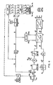
By using a voltage impressing pulse inverter and voltage impressing, use can be made of the setup shown in Fig. 2.
-
A subordinate slip regulating circuit is provided which receives its required slip value ω
from a superimposed regulator such as, for example, a rotational speed regulating device, a torque input value or, as shown, from a stator frequency regulator (80 to 86).
-
The output value of the slip frequency calculator is the actual value fed to the ω
2 regulator (89), the stator frequency is the output quantity. The stator frequency, the required value of the rotor frequency and the input value for the value of the rotor interlinking flux are used to build the required voltage components (u
x, u
y) in the direction of the rotor interlinking flux and at right angles to it (93).
-
The spatial argument angle vI for the stator angle is formed from ω1, defined in known manner from v = ωl, and, from the calculation of the sin-cos values (91), the required values for the 3 phase windings voltages are formed in known manner via 2 coordinate transformations (94 and 95).
-
The slip-frequency limitation is arrived at by providing a limiter (85) in known manner for the required value of the slip. The internal slip- regulating circuit was not possible until now, because it was lacking an accurate, dynamically correct measuring possibility. In Fig. 2, PWM = pulse width modulation process, PWR = pulse dc/ac inverter.
-
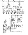
With input data of the stator current via a two-point regulator process or subordinated current regulation and stator voltages as regulated quantities (controller outputs), the setup shown in Fig. 1 (Fig. 2 - Trans?) can be used in modified form as illustrated in Fig. 3.
-
According to Fig. 3, a subordinated regulating circuit is provided for the stator current component ilx, whereby the required value, shown as an example, is formed from a torque input data (110) or from a rotational speed regulating device or from a stator frequency regulator. According to Fig. 1, the output from the ilx calculator is the required value ilxc fed to the ilx-regulator (115), the stator frequency is the output quantity.
-
The further refinement is very similar to that in Fig. 2. The required value of the current producing the torque and the input data for the value of the rotor interlinking flux are used to determine the input data for the current components i
x and i
y (119), whereby i*
1x is formed directly from the required value of the i
lx-regulator via a phase-shifting section (or lag element) of the first order whose time constant is dependent on the i
lx regulating circuit. In this case, slip limitation is attained by limiting the required value of the current component producing the torque (112).
-
Instead of building a frequency ωl and from it the angle v, to carry out a coordinate transformation via a subordinate regulating circuit, with the calculated value for the slip frequency formed via the rotor emf components, or with the calculated value ilxc as a control variable, the angle v1 can be obtained directly from the rotor emf components.
-
For example, v1 can be computed directly from the arctan of the quotient e2β/e2αor from arccos e2a||e2| and from signum e2α' signum e2β and signum ω1. Taking the sign of e2α, e20 and w1 into account leads to a definition of the value of ν1 in the angular range 0 to 2π.
-
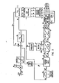
Fig. 4 shows a signal processor which uses a determination of this type of the angle v from the rotor emf components. In their assignment to the asynchronous motor, the current components i
x and i
y are thereby spatially oriented directly to the rotor emf components.
-
The emf calculator shown in Fig. 1 yields the rotor emf components. The determination of the angle in the v
1-calculator (150) is effected as described above. The determination of the current components i
x and i
y along with the two transformations, are already known from the preceding operating examples. The formation of the actual value of the stator frequency ω
1 from the differentiation of the angle v
1 (145) is masked out with the passage of the value of the angle 2π to 0 (or 0 to 2π with w
I < 0), and the last value w
1 is briefly retained.
-
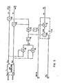
Fig. 5 illustrates a solution for the direct formation of the pair of values cos v1 and sin ν1 from the components of the rotor emf. The value of the rotor emf vector is formed via the two multipliers (160, 161), the summation unit (162) and the unit for forming the square root (163). The division (165, 166) of the components of the rotor emf by the value directly yields the calculated values cos ν1, sin ν1.
-
The determination of the stator frequency to effect a stator frequency regulation can be carried out with the supplementary device enclosed in the broken lines in Fig. 5. When operating the asynchronous motor in both directions of rotation, the sign of the stator frequency (signum ω1) must be known in order to determine the pair of values sin ν1 and cos ν1 and the input data for the stator frequency. The sign of the stator frequency may easily be determined from the control procedure to be described below.
-
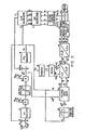
The current-impressing intermediate circuit inverter with smoothed intermediate circuit current and phase-sequence quenching has established itself as a relatively economical and operationally reliable inverter and is frequently employed. Consequently, in the following, a description will be given of the use of the above-described procedure in association with this inverter. Fig. 6 shows a signal processor for an inverter with current- impression in the intermediate circuit using the components of the rotor emf supplied by the emf calculator, and using the direct spatial assignment of the phase current to the rotor emf vector. Other than with the data for the instantaneous value of the required value of the stator's phase current (Fig. 4), here the angle and the value are given separately. In so doing, the angle which determines the conductive state of the dc/ac converter (203) on the motor-side is formed from the angle v1 and a supplementary angle v which gives the rotation of the stator current required value vector with respect to the rotor emf vector.
-
The determination of the value of the intermediate circuit current is derived, on the other hand, in known manner from the magnetization current component and the torque-building current component which is given by the regulator belonging to the external regulator circuit. PD (189) denotes a phase-lead element with a proportional part and a differentiating part. Apart from the commutating intervals, only two phase conductors of the motor carry the current and the stator current's space vector consequently carries out an unsteady jerky rotational movement. The conduction state is set by the firing pulse input data. Because the angle ν1, and consequently, on account of the calculation being independent of the initial conditions, the rotor emf components need only be known outside the commutation time, it is possible, with the aid of a coordinate transformation from polar into Cartesian coordinates, to determine the instantaneous value of the stator current, in accordance with the invention, from the intermediate dc current as a measure of the value of the stator current space vector, and from the conducting state of the dc/ac converter on the motor side, as a measure of the spatial argument angle.
-
After the conversion to rectangular coordinates, the current is and fed as described above to the rotor emf to the slip calculator. It is consequently possible to dispense with two current transformers and the transformation of the actual values of the current from the (a, b, c) into the (α,β) system of coordinates.
-
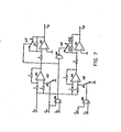
Fig. 7 illustrates the described simulation (balancing) of the motor's terminal currents from the intermediate circuit current and the conducting state of the dc/ac converter on the motor side, in an arrangement with analog and digital components.
-
Here, izk is the intermediate circuit current which is measured by means of a current transformer and which is used here both for regulating the rectifier on the power supply side and also the value signal for the stator current.
-
The logic signals T are determined from the conductive state of the motor-side rectifiers and always have the logic "H" when the associated rectifier conducts. Thereby, the first index of the logic signal indicates the phase conductor with which the assigned rectifier diode is connected, the second index is equal to 1 for the rectifier diode connected to the cathode side and equal to 2 for the rectifier diode connected to the anode side of the power supply side-rectifier.
-
Regulation of the asynchronous motor can be effected with torque input data as, for example, with the arrangement shown by way of example in Fig. 3 or with superimposed regulation of the stator frequency as, for example, in Fig. 2, or with increased requirements with respect to the independence of the rotational speed on the load torque by using a rotational speed controller. In this connection, in accordance with Fig. 4 and Fig. 6, there is specified a required value (np·ωm)* which is proportional to the desired rotational speed. To this signal is added the computed value of the slip, the addition being made via a first order delay element (141, 181).
-
The value of the sum is fed as a required value to the stator frequency regulating circuit. The further developed form of the regulator is as described in the preceding examples.
-
Regulation of the rotational speed is also possible by using a tachometer.
-
In the fractions in equations (3) and (4), the numerators and the denominators approach the value zero when the motor tends to its state of rest. As a result, the procedure so far described breaks down in a critical region close to zero frequency, the breakdown being greater the greater the error in the motor parameters set in the regulator. In accordance with the invention, measures are provided to narrow down this critical region. This is effected by shifting the scaling factors in known manner in the calculator circuits.
-
In accordance with the invention, additional measures are provided to make possible a different way of operating in the critical region, namely to frequency control the processes of starting, braking, stopping and reversing. These measures, which are in accordance with the invention, will be described in the following.
-
Fig. 8 shows a supplementary apparatus which makes possible a frequency-controlled passage through a zone close to the zero-passage of the stator frequency. In the process, illustrated here by way of example by an ω1-regulator with a subordinated slip control circuit, the slip regulator is masked out on undershooting a frequency value aω1N, in that a switch-over takes place to the lower path (218, 219). A limited value (dω1/dt)min is fed via a high amplification proportional element (218) and the following limiting stage (219) to the integrator of a slip-regulator which, in Fig. 8, takes the form of a PI-regulator, the sign of (dω1/dt)min being the same as that of the deviation Δω1 and which vanishes at Δω1 = 0.
-
With the supplementary apparatus, starting and braking to a stop, reversing and continuous running is possible in the control range. Transient effects which arise in the control range, and which, together with the reduction of the internal torque, which takes place with accelerating or braking processes within the control range, are troublesome and can be circumvented with an enlarged supplementary apparatus for passage through the control range in a quasi-regulated manner.
-
Fig. 9 shows an ilx regulator and PI-behavior is assumed for the regulator of the subordinate circuit.
-
In addition to the condition ω1 < aωIN, that is, operation within the control range, there now enters a second condition denoted by b, with b > a, which ensures that the quantity dω1/dt, which can be evaluated from the slip regulator or the ilx-regulator, or from the direct orientation on the rotor emf vector, and which can be held constant on entering into the control region and/or on traversing the control range, is determined from a steady state, and which ensures that sufficient time has elapsed after a jump in the required value until entry into the control range so that, for example, the regulation for the subordinate circuit has reached, up to that time, the steady state.
-
By observing the above-required conditions, the logic shown in Fig. 9, which operates via the flip-flop (254) and via a holding and scanning element (236), holds the input of the PI-regulator (238, 239) constant at the value immediately prior to entry into the control range, until either the condition Δω1 is fulfilled or until the control range has again been left.
-
On the other hand, on starting-up from the state of rest or with a change in the required value of the external control circuit after con- tinuous operation in the control range, (dω1/dt) is preset via the path with the proportional amplifier (242) and the limiter (243).
-
When using the enlarged supplementary device, reversing which begins in the regulation rangejor braking processes out of the regulation range into the control range,take place with constant internal torque and with almost no transient effects in the field.
-
In addition, on starting from the state of rest, the required value w
of the slip frequency becomes such that the stator frequency is greater than the frequency limit aω
1N of the control range and that, as a result, the control range can be immediately left on starting. As a result of this, regulated operation of the asynchronous motor can be achieved in almost all operating cases which can occur without it being necessary to have an accurate knowledge of the motor's parameters.
-
Obviously, the supplementary device shown in Fig. 8 and the enlarged supplementary device shown in Fig. 9 can be transferred to all the procedures presented in Claims 2 to 9 and 12 to 14, and bring the following advantage:
-
By using the,control range, there is now no longer any need for an accurate knowledge of the parameters RI, R2, LS1' LS2 and M, which would otherwise be necessary at low rotor frequencies. As a result, the advantage of the parameter-insensitive regulating process, which would otherwise exist only at high stator frequencies, is extended to the entire rotational speed range. On the other hand, use is made of the benefit that the switch from control to regulation proceeds out of the control range directly and without a required knowledge of initial conditions.
-
The regulating processes illustrated in the description can be extended without large additional expenditures to the field-weak region. In the process, as shown, for example, in Figs. 2 and 3, u
x, u
y, or i
x i
y must be incorporated both in the input data and in the superimposed regulating circuit.
-
In Fig. 2, the required value of the slip is multiplied in two places, before and after the limiting element (85), by the reciprocal of the field-weakening ratio. On the other hand, on forming the required value signal or the input value i
x in accordance with Figs. 3, 4 or 6, only one multiplication is carried out, namely before the limiting stage (112, 147, 187). The input value for the rotor interlinking flux is modified in a frequency- dependent manner via the characteristic curve diagrams, such as (92) in Fig. 2 or (118) in Fig. 3, and serves as an input quantity for forming the u-input value (93) or the i-input value (119).
-
The change in the rotor flux input data value in the field-weakening region has a negligibly small effect on the required condition d|ψ2|/dt ≅ 0, which is the prerequisite for the ω2c and ilxc calculation, as well as for the orientation with respect to the rotor emf components.
REFERENCES
-
- 1. J8tten, R. State of the art for regulated 3-phase drive systems. VDE-Fachberichte, 30, VDE Verlag, Berlin, 1979.
- 2. J8tten, R. Dynamic behavior of asynchronized motors energized with rectified current. ETG-Fachtagung, ETG-Fachberichte, No. 5, October, 1979.
- 3. Abbondanti, A. and Brennen, M. Variable speed induction motors use electronic slip calculator based on motor voltages and currents. IEEE-Transactions, vol. IA-11, Sept.-Oct. 1975, No. 5.
- 4. Venkataram, R. Ramaswami, B and Holtz, J. Electronic analog slip calculator for induction motor drives. IEEE Transactions. Industry Electronics and control instruments. Vol. IEC 1=27, 1980.


 iy) or for the input data of the stator current vector via its components (i
