EP0091233A2 - Système et procédé d'alignement et mesurage auto-focus - Google Patents
Système et procédé d'alignement et mesurage auto-focus Download PDFInfo
- Publication number
- EP0091233A2 EP0091233A2 EP83301638A EP83301638A EP0091233A2 EP 0091233 A2 EP0091233 A2 EP 0091233A2 EP 83301638 A EP83301638 A EP 83301638A EP 83301638 A EP83301638 A EP 83301638A EP 0091233 A2 EP0091233 A2 EP 0091233A2
- Authority
- EP
- European Patent Office
- Prior art keywords
- substrate
- mask
- focal plane
- imaging means
- photodiodes
- Prior art date
- Legal status (The legal status is an assumption and is not a legal conclusion. Google has not performed a legal analysis and makes no representation as to the accuracy of the status listed.)
- Withdrawn
Links
Images


Classifications
-
- G—PHYSICS
- G03—PHOTOGRAPHY; CINEMATOGRAPHY; ANALOGOUS TECHNIQUES USING WAVES OTHER THAN OPTICAL WAVES; ELECTROGRAPHY; HOLOGRAPHY
- G03F—PHOTOMECHANICAL PRODUCTION OF TEXTURED OR PATTERNED SURFACES, e.g. FOR PRINTING, FOR PROCESSING OF SEMICONDUCTOR DEVICES; MATERIALS THEREFOR; ORIGINALS THEREFOR; APPARATUS SPECIALLY ADAPTED THEREFOR
- G03F9/00—Registration or positioning of originals, masks, frames, photographic sheets or textured or patterned surfaces, e.g. automatically
- G03F9/70—Registration or positioning of originals, masks, frames, photographic sheets or textured or patterned surfaces, e.g. automatically for microlithography
- G03F9/7069—Alignment mark illumination, e.g. darkfield, dual focus
-
- G—PHYSICS
- G03—PHOTOGRAPHY; CINEMATOGRAPHY; ANALOGOUS TECHNIQUES USING WAVES OTHER THAN OPTICAL WAVES; ELECTROGRAPHY; HOLOGRAPHY
- G03F—PHOTOMECHANICAL PRODUCTION OF TEXTURED OR PATTERNED SURFACES, e.g. FOR PRINTING, FOR PROCESSING OF SEMICONDUCTOR DEVICES; MATERIALS THEREFOR; ORIGINALS THEREFOR; APPARATUS SPECIALLY ADAPTED THEREFOR
- G03F9/00—Registration or positioning of originals, masks, frames, photographic sheets or textured or patterned surfaces, e.g. automatically
- G03F9/70—Registration or positioning of originals, masks, frames, photographic sheets or textured or patterned surfaces, e.g. automatically for microlithography
- G03F9/7003—Alignment type or strategy, e.g. leveling, global alignment
- G03F9/7023—Aligning or positioning in direction perpendicular to substrate surface
- G03F9/7026—Focusing
Definitions
- This invention relates generally to optical focusing, aligning, and measuring systems and methods, and more specifically to such optical systems and methods for use in the fabrication of semiconductor integrated circuits.
- Integrated circuits are electronic devices that are fabricated from a wafer of semiconductor material, such as silicon, by subjecting the wafer to a series of processing steps.
- the wafer, or substrate is coated with a light- sensitive or photoresist material and then aligned with respect to a mask which allows light to expose the photoresist material in accordance with a predetermined circuit pattern.
- This pattern is subsequently used for developing circuit elements employed in forming the integrated circuits. Circuit patterns are thus transferred to the wafer photolithographically, with several different masks being used to form a typical integrated circuit. Successive wafer alignments with respect to the masks are critical to . insure functional integrated circuits.
- Proximity or out-of-contact printing where the mask and the wafer are separated by a small gap (typically in the ten micrometer to fifty micrometer range), is a popular integrated circuit fabrication technique.
- Process yields using proximity or out-of-contact printing are better than those attainable using contact printing because of reduced mask impairment and improved mask lifetime due to the absence of contact between the mask and the wafer during printing.
- the proximity or out-of-contact method of printing is also the only method that can be used in X-ray lithography.
- Proximity or out-of-contact printing is not without problems, however, because the gap separating the mask and the wafer must be great enough to allow for the surface flatness tolerances in both the mask and the wafer, but small enough to minimize diffraction effects on the projected circuit pattern.
- Integrated circuits are commonly designed with circuit pattern details which require alignment to1erances ⁇ in the submicrometer range.
- Magnification optics of 100X to 1000X are commonly used in aligning the wafer with respect to the mask to resolve the alignment to the required tolerances, but such high magnification optics with high numerical apertures have a depth of field that is less than the gap separating the mask and the wafer. This means that either the mask or the wafer, but not both, can be in focus at any one time, thereby causing great difficulty in positioning the wafer for proper alignment with respect to the mask.
- an optical system is needed that is capable of simultaneously displaying to an operator a magnified and focused view of both a mask and an out-of-contact wafer to facilitate mask-wafer alignment.
- a measurement system is further needed that is capable of measuring and adjusting the gap separating the mask and the wafer to a value suitable for proximity or out-of-contact printing and that is also capable of measuring line widths and other surface features of the mask or the wafer.
- an alignment system is needed that is capable of more precisely aligning the wafer with respect to the mask.
- a gap measurement device is shown in U.S. Patent 4,165,178, but this device is a go/no-go optical gauge that is limited to sensing separation distance at edges only.
- the use of a single moveable converging lens to measure the gap between a mask and a wafer is described in U.S. Patent 4,070,116.
- careful study of this patent reveals problems that are inherent in the use of a single moveable converging lens for gap measurement.
- the governing optics equation states that the reciprocal of the focal length of a lens equals the sum of the reciprocals of the object distance and the image distance. Since the focal length of a lens is constant, an increase in the image distance is balanced by a decrease in the object distance.
- U.S. Patent 4,070,116 the moveable lens is employed with a fixed focus detector to measure the gap between the mask and the wafer. After focusing an image of the mask onto the focus detector, the lens is moved away from the focus detector to a position at which the lens focuses an image of the wafer onto the focus detector. This displacement or change of position of the lens increases the image distance from the lens to the focus detector and causes a corresponding decrease in the object distance from the lens to the object plane.
- U.S. Patent 4,070,116 Due to this decrease in the object distance, the lens displacement must be greater than the gap between the mask and the wafer.
- the gap measurement calculation described in U.S. Patent 4,070,116 therefore is quite complex and requires knowledge of the mask image distance and the mask object distance as well as the lens displacement.
- U.S. Patent 4,070,116 discloses no provision for establishing measurement accuracy greater than the depth of field of the optics.
- Focus detectors sensing light intensity variations are also known to exist in the prior art. See, for example, U.S. Patents3,356,854 and 4,070,116, which show optical fibers attached to photodetectors and signal conditioning circuitry.
- Another object of this invention is to provide apparatus capable of measuring the gap between a mask and a substrate by measuring the displacement of a moveable lens that alternately focuses on a surface of the mask and on a surface of the substrate.
- Another object of this invention is to provide apparatus and a method for positioning a substrate at a location parallel to a mask and spaced a predetermined distance from the mask.
- Another object of this invention is to provide apparatus for optically measuring the flatness of a surface.
- a further object of this invention is to provide imaging apparatus and a method for simultaneously providing a magnified and focused view of a mask and a substrate that are separated by more than the depth of field of the imaging optics.
- a further object of this invention is to provide imaging apparatus for simultaneously displaying magnified and focused views of two laterally-spaced areas of both a mask and a substrate when the mask and the substrate are separated by more than the depth of field of the imaging optics.
- Still a further object of this invention is to provide an improved focus detector comprising an array of photodiodes for allowing measurement of surface features of a mask or a substrate, as well as focus detection of a surface of the mask or the substrate.
- an auto-focusing optical alignment and measurement system for more efficiently and precisely aligning a semiconductor wafer or substrate with respect to an out-of-contact or spaced-apart mask containing microcircuitry features to be photolithographically or X-ray transferred to the substrate.
- This system includes an arrangement of lenses, one of which is a moveable convergent lens, for alternately focusing images of the mask and the substrate onto a photodiode array.
- the photodiode array with its associated signal processing circuitry, serves as a focus detector.
- Control apparatus using the focus detector to provide a feedback signal, adjusts the displacement of the moveable lens to equal the separation or gap between the mask and the substrate with an accuracy better than the-depth of field of the optics of the system.
- the moveable lens alternately focuses on the mask and substrate at a rate faster than the response rate of human vision.
- Microscope viewing optics and a strobe light timed to flash when either the mask or the substrate is focused, allow an operator to see a magnified view of both the mask and the substrate superimposed and in focus.
- the system can also be employed to measure surface flatness of either the mask or the substrate.
- the degree of parallelism between the mask and the substrate can be measured.
- Substrate positioning apparatus allows the operator to adjust the separation or gap between and the alignment and parallelism of the mask and the substrate prior to photolithographic printing.
- two separate sets of imaging optics are provided to permit viewing of a split-field image of separate laterally-spaced areas of both the mask and the substrate. This capability simplifies the alignment procedure, which can then be performed while simultaneously viewing those areas.
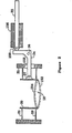
- FIG. 1 there is shown an auto-focusing alignment and measurement system according to the preferred embodiment of this invention.
- a photolithographic mask 10 is held by a mask frame 12 and is positioned above a semiconductor substrate 14 that is in turn mounted on a substrate holder 16.
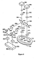
- a moveable, convergent objective lens 18 is attached to a lens frame 20 and is positioned by a piezoelectric transducer 22 acting on a lever 24 that pivots about a pivot point 26.
- the motion of the moveable lens 18 is bounded by an upper position 154 and a lower position 152.
- the moveable lens 18, attached to the lens frame 20 is guided by two flexures 21 and 23 attached to a housing 25.
- flexures 21 and 23 permit movement of the lens 18 between the upper position 154 and the lower position 152, but constrain lens motion in all other directions.
- the flexures 21 and 23 also act as springs to keep the lever 24 in contact with a transducer plunger 150 of the piezoelectric transducer 22, which is mounted in a transducer support 156.
- the lever 24 passes through a clearance hole 155 in the housing 25 and is fastened to the lens frame 20 at a lever attachment point 27.
- the moveable lens 18 is shown in solid lines at a mask focus position 136 where its focal point 142 is coincident with the lower surface of the mask 10.
- the moveable lens 18 is shown in dotted lines at a substrate focus position 138 where its focal point 144 coincides with the upper surface of the substrate 14, which is separated from the mask 10 by a gap 146.
- a displacement 140 of the moveable lens 18 from the mask focus position 136 to the substrate focus position 138 is equal to the gap 146 between the mask 10 and the substrate 14.
- the moveable lens 18 is disposed along a vertical focusing lens optical path 132 coincident with the optical axis 130 of the moveable lens.
- a beam splitter 28 is disposed along this vertical optical path 132 above the moveable lens 18 to provide a horizontal viewing lens optical path 134.
- a viewing lens assembly 38 which contains a convergent transfer lens 40 and a convergent focusing lens 42, is disposed along the horizontal viewing lens optical axis 134 to present a focused and magnified image of the mask 10 or the substrate 14 to an observer 44.
- the substrate holder 16 is mounted on a chuck 48 that is capable of translational movement perpendicular to the plane of the mask 10 in a Z direction 49 and also capable of rotational movement in 7 and ⁇ directions 57 and 59 about orthogonal X and Y axes, respectively.
- the chuck 48 is mounted on a stage 50 translatable in X and Y directions 51 and 53, respectively, and rotatable in a ⁇ direction 55 about a Z axis, all in a plane parallel to the mask 10.
- Motion of the substrate holder 16 in the Z direction is monitored by a displacement transducer 52 electrically connected to a displacement transducer signal conditioning unit 56, which provides a Z position output signal 58.
- the position of the substrate 14 is controlled by a digital computer 99 (see Figure 4) through a series of stepper motors and controllers.
- Stage 50 is rotated in the ⁇ direction 55 by a e stepper motor and controller 60 in response to a 9 motion signal 62 and is translated in the X and Y directions 51 and 53 by X and Y stepper motors and controllers 68 and 64 which respond to X and Y motion signals 70 and 66, respectively.
- the chuck 48 is moved in the Z direction 49 by a Z stepper motor and controller 72 in response to a Z motion signal 74 and is moved in the ⁇ and 8 directions 57 and 59 by a 7 and 6 stepper motor and controller 91 in response to ⁇ and ⁇ motion signals 95.
- a strobe light 46 is provided for illuminating the mask 10 and the substrate 14.
- a strobe power supply 76 is coupled to the strobe light 46 for causing the strobe light to flash in response to a strobe signal 78.
- a pulsed light source could be provided by employing a constant light source and a chopping device, such as a tuning fork or rotating disk with a window.
- the piezoelectric transducer 22 for moving the lens 18 is driven by a high voltage operational amplifier driver 80 in response to a piezo voltage signal 82.
- lens motion could be provided by an electromagnetic transducer, such as a voice coil.
- Each photodiode in the photodiode array 36 is connected to a signal conditioning circuit 84.
- the signal conditioning circuit 84 Upon receipt of a start scan signal 88, the signal conditioning circuit 84 scans the voltage output signal from each photodiode at a scan rate determined by a clock signal 90.
- the signal conditioning circuit 84 converts these photodiode signals to a video analog signal 86 indicative of the pattern of the light impinging on the photodiode array 36.
- the operator chooses the operational mode of the alignment and measurement apparatus via a keyboard 92 coupled to the digital computer 99 (see Figure 4) for supplying a function input signal 94 thereto.
- the digital computer 99 in turn communicates with the operator via an output device 96 controlled by a status output signal 98.
- the output device 96 is a cathode ray tube display.
- the digital computer 99 and its associated interfacing provide four primary control functions, namely: focus detection, moveable lens positioning, strobe flashing, and substrate positioning. Instructions for carrying out these control functions are stored in a read-only memory (ROM) 110.
- a processor 108 executes the instructions stored in the ROM 110 and uses a random-access memory (RAM) 112 for data storage.
- a digital to analog converter 100, an analog to digital converter 102, a digital output port 104, and a digital input/output port 106 are connected to the processor 108, the ROM 110, and the RAM 112 via a data bus 114, an address bus 116, and a control bus 118 in a manner well known in the art to provide interfacing for effecting the control functions.
- An image 160 of the mask 10 or the substrate 14, as seen by the photodiode array 36, is composed of areas of relatively bright light 164 and relatively dim light 162 corresponding to surface features on the mask 10 or the substrate 14.
- Each photodiode in the photodiode array 36 generates a voltage output signal that is proportional to the intensity of light impinging on it.
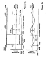
- Such photodiode signals for an image 160 in focus and out of focus are shown plotted verses photodiode position 170 in Figures 5a and 5b, respectively.
- photodiodes in a bright area produce a high signal 172 while photodiodes in a dim area produce a low signal 174.
- These high and low signals 172 and 174 bound a differential signal.
- the photodiode signal strength 166 at boundaries 182 and 186 has a maximum signal transition rate, and the differential signal has a maximum amplitude Dp.
- the photodiode signal strength 168 at boundaries 182 and 186 has a smaller signal transition rate, and the differential signal has a smaller amplitude D U .
- the digital computer 99 provides the focus detection control function by first supplying the start scan signal 88 and the clock signal 90 at the digital output port 104 and then analyzing the video analog signal 86 as converted by the analog to digital converter 102.
- the image 160 is in focus when the aforementioned differential signal has a maximum amplitude or when the signal transition rate at the boundaries 182 and 186 is at a maximum. At this point the width 184 of a surface feature of the mask 10 or the substrate 14 can be measured.
- the digital computer 99 controls the position of the moveable lens 18 by controlling the magnitude of the piezo voltage signal 82.
- the mask focus position 136 and the substrate focus position 138 must be determined to a high degree of accuracy. Simply focusing the moveable lens 18 on the mask 10 or the substrate 14 would provide a lens position 136 or 138 accurate within the depth of field of the optics of the alignment and measurement apparatus. However, a much higher accuracy is required and is achieved by determining the center of the depth of field of the optics.
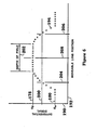
- the method employed to determine the center of the depth of field of the optics will now be described with reference to Figure 6, where the amplitude 190 of the differential signal between the high and low photodiode signals (produced by bright and dim areas of an image of the mask or the substrate) is plotted against moveable lens position 192.
- Each point 194 in this plot represents measurement of the amplitude of the differential signal for a complete scan of the photodiode array 36 (see Figure 1).
- the moveable lens position 192 is changed from left to right, the amplitude 190 of the measured differential signal increases from an unfocused level 180 to a focused level 178, remains constant at the focused level 178 throughout the depth of field 202 of the optics, and thereafter decreases back to the unfocused level 180.
- the center of the depth of field 202 is determined by employing a threshold differential signal 200 to establish a first threshold position 204 and a second threshold position 206.
- a center position 208 is calculated from the average of these two threshold positions.
- the digital computer 99 To measure the gap 146, the digital computer 99 first determines the piezo voltage signal that best positions an image of the mask 10 onto the photodiode array 36 (this piezo voltage signal corresponds to the mask focus point 232) and then determines the piezo voltage-signal that best positions an image of the substrate 14 onto the photodiode array 36 (this piezo voltage signal corresponds to the substrate focus point 234). The digital computer 99 then converts these two piezo voltage signals into moveable lens positions by using a stored calibration conversion.. The measured gap 146 is simply the difference between these lens positions and is displayed to the operator by employing the digital input/output port 106 to provide a status output signal 98.
- the stored calibration conversion used to convert the piezo voltage signals to moveable lens positions is determined by employing the displacement transducer 52 (see Figure 1), which is a linear voltage displacement transducer in the preferred embodiment of the present invention. This is accomplished by moving the substrate 14 and the moveable lens 18 to positions at which an image of the substrate 14 is best focused onto the photodiode array 36.
- the displacement transducer 52 directly measures substrate displacement and indirectly measures moveable lens displacement as long as the moveable lens 18 is moved with the substrate so as to remain in focus.
- any hysteresis or nonlinearity in moveable lens position as a function of piezo voltage signal may be measured and utilized to generate the calibration conversion, which is thereupon stored in RAM 112 for subsequent usage.
- Strobe light 46 is flashed each time a focus measurement is taken by simultaneously sending the strobe signal 78 and the start scan signal 88 through the digital output port 104.
- the flash duration is long enough to allow a complete scan of the photodiode array 36.
- the first phase of the substrate positioning control function is the adjustment of the gap 146 separating the mask 10 and the substrate 14 to a predetermined value. This is illustrated in Figure 8, where the positional oscillations of the moveable lens 18 and the adjustment of an actual substrate position 246 with respect to a desired substrate position 248 are plotted against time 222.
- a first gap measurement 250 is made and compared by the digital computer 99 with a desired gap measurement 258.
- the substrate 14 is then moved in the Z direction 49 and a second gap measurement 252 is made and compared with the -desired gap measurement 258. This process is repeated with a third gap measurement 254, a fourth gap measurement 256, and more gap measurements, if necessary, until the actual gap measurement equals the desired gap measurement 248.
- the second phase of substrate positioning, or alignment may begin.
- the operator views superimposed images of the mask 10 and the substrate 14 through the viewing lens assembly 38 and positions the substrate 14 by directing the digital computer 99, via the keyboard 92, to provide control signals for controlling movement of the stage 50 with the substrate 14 supported thereon.
- These control signals comprise the X motion signal 70, the Y motion signal 66 and the 6 motion signal 62, which are provided at the digital output port 104 for directing the X, Y and Z stepper motors and controllers 68, 64 and 72, respectively, to move the stage 50.
- the auto-focusing alignment and measurement system of the present invention can also be employed to measure the degree of flatness of the upper surface of the substrate 14. This measurement is made by positioning the moveable lens 18 at a succession of positions that best focus images of spaced-apart areas of the upper surface of the substrate 14 onto the photodiode array 36. These spaced-apart areas of the upper surface of substrate 14 are brought into the field of view of the focusing lens optics by moving the stage 50 in the X and Y directions 51 and 53, repectively.
- the degree of surface flatness of the upper surface of the substrate 14 is computed by the computer 99 from the range of moveable lens displacements effected to position the moveable lens 18 at the aforementioned succession of best-focus positions.
- the auto-focusing alignment and measurement system of the present invention can be employed to measure the degree of parallelism between the lower surface of the mask 10 and the adjacent upper surface of the substrate 14 by moving the mask and the substrate together in the X and Y directions 51 and 53, respectively, and by measuring the gap 146 between those surfaces (see Figure 3) at several different locations.
- the upper surface of the substrate 14 can be adjusted to be parallel to the lower surface of the mask 10 by rotating the substrate in the T f and 6 directions 57 and 59 about the orthogonal X and Y axes (which are both perpendicular to the optical axis 130 of the moveable lens 18) to a position that equalizes the gap measurements made at those different locations.
- the mask frame 12 can be selectively locked to the substrate holder 16 or the stage 50 as indicated by the dashed selectively-operable coupling 61 in Figure 1. When so locked, the mask frame 12 moves together with the stage 50 in the X and Y directions 51 and 53. Once the gap measurements for determining the degree of parallelism between the adjacent surfaces of the mask 10 and the substrate 14 have been-made, the mask frame 12 is unlocked from the substrate holder 16 and the stage 50. The substrate holder 16 may then be rotated relative to the mask frame 12 by the 7 and 8 stepper motor and controller 91 to position the upper surface of the substrate 14 parallel to the adjacent lower surface of the mask 10.
- right and left focusing and viewing optics 262 and 264 provide the operator with a binocular view of spaced-apart right and left alignment marks 266 and 268, respectively, on the mask 10 held by the mask frame 12 and also of corresponding spaced-apart right and left alignment marks 320 and 322 on the substrate 14 supported beneath the mask.
- Both the right and left focusing and viewing optics 262 and 264 of the binocular embodiment are of the same design and function in the same manner as in the previously-described monocular embodiment.
- right and left moveable lenses 270 and 272 are adapted for movement along parallel, vertical right and left focusing lens optical paths 271 and 273, respectively.
- a right beam splitter 274 is disposed in the vertical right focusing lens optical path 271 above the right moveable lens 270 for providing a horizontal right viewing lens optical path 324
- a left beam splitter 276 is similarly disposed in the vertical left focusing lens optical path 273 above the left moveable lens 272 for providing a horizontal left viewing lens optical path 326 parallel to the horizontal right viewing lens optical path.
- a right transfer lens 278 and a right focusing lens 282 are disposed along the vertical right focusing lens optical path 271 above the right beam splitter 274 to focus a magnified image of the right alignment mark containing area of the mask 10 or the substrate 14 onto a right focus detector 286 also disposed along the vertical right focusing lens optical path at the focal plane of the right focusing lens 282, while another right transfer lens 290 and another right focusing lens 294 are disposed along the horizontal right viewing lens optical path 324 to present a magnified and focused image of the same right alignment mark containing area to the operator's right eye 298.
- a left transfer lens 280 and a left focusing lens 284 are disposed along the vertical left focusing optical path 273 above the left beam splitter 276 to focus a magnified image of the left alignment mark containing area of the mask 10 or the substrate 14 onto a left focus detector 288 also disposed along the vertical left focusing lens optical path at the focal plane of the left focusing lens 284, while another left transfer lens 292 and another left focusing lens 296 are disposed in the horizontal left viewing lens optical path 326 to present a magnified and focused image of the same left alignment mark containing area to the operator's left eye 300.
- a right beam splitter 304 is disposed along the horizontal right viewing lens optical path 324 between the right focusing lens 294 and the operator's viewing station to additionally provide a vertical right viewing optical path
- a left beam splitter 302 is disposed along the horizontal left viewing lens optical path 326 between the left focusing lens 296 and the operator's viewing station to additionally provide a vertical left viewing optical path parallel to the vertical right viewing optical path.
- Right and left television cameras 310 and 312 are respectively disposed along the vertical right and left viewing optical paths for viewing the magnified and focused images of the right and left alignment mark containing areas of the mask 10 and the substrate 14.
- right and left television cameras 310 and 312 are coupled by right and left television monitors 314 and 316, respectively, to an automatic alignment recognition system 318 well known in the prior art.
- the output 306 of the automatic alignment recognition system 318 is coupled to the computer 99 via the analog to digital converter 102.
- the computer 99 provides X, Y and 9 motion control signals for effecting movement of the stage 50 to position the substrate 14 in alignment with respect to the mask 10.
- the viewing optics 38 of Figures 1 and 3 may be replaced with a television camera and a screen to provide the operator with a display of a magnified image of the mask 10 and the substrate 14.
- the two sets of viewing optics 290-296 of Figure 9 may also be replaced with two television cameras and a screen to similarly provide the operator with a split-field display of a magnified and focused image of the right and left alignment mark containing areas of the mask 10 and the substrate 14.
- Each of the moveable lenses 18, 270 and 272 employed in the previously-described embodiments of the present invention may comprise, for example, a Zeiss Epiplan 46-20-93 20X microscope objective lens driven sinusoidally at a frequency of 20 H z.
- the piezoelectric transducer 22 for moving or oscillating each moveable lens may comprise a Burleigh PZ-44, and the high voltage operational amplifier 80 for driving the piezoelectric transducer may comprise a Burleigh PZ-70.
- the focusing lenses 34, 42, 282, 284, 294 and 296 in the focusing lens and viewing lens assemblies of the previously-described embodiments may, for example, provide a 10X magnification.
- Each of the focus detectors 36, 286 and 288 employed in the previously-described embodiments preferably comprises a Reticon 1024G photodiode array with .001 inch spacing between photodiodes, while the associated signal conditioning circuit 84 preferably comprises a Reticon RC100B/RC106 signal conditioning circuit operable at a scan rate of 500 KHz.
- the strobe light 46 for illuminating the mask 10 and the substrate 14 may comprise a 15 watt xenon lamp with an ultraviolet filter, and the associated strobe power supply 76 may comprise an EG&G PS-302 power supply for pulsing the strobe light at 40 Hz with a pulse duration of .001 second.
Applications Claiming Priority (2)
| Application Number | Priority Date | Filing Date | Title |
|---|---|---|---|
| US06/364,681 US4615621A (en) | 1982-04-02 | 1982-04-02 | Auto-focus alignment and measurement system and method |
| US364681 | 1982-04-02 |
Publications (2)
| Publication Number | Publication Date |
|---|---|
| EP0091233A2 true EP0091233A2 (fr) | 1983-10-12 |
| EP0091233A3 EP0091233A3 (fr) | 1984-05-23 |
Family
ID=23435594
Family Applications (1)
| Application Number | Title | Priority Date | Filing Date |
|---|---|---|---|
| EP83301638A Withdrawn EP0091233A3 (fr) | 1982-04-02 | 1983-03-24 | Système et procédé d'alignement et mesurage auto-focus |
Country Status (3)
| Country | Link |
|---|---|
| US (1) | US4615621A (fr) |
| EP (1) | EP0091233A3 (fr) |
| JP (1) | JPS58182607A (fr) |
Cited By (2)
| Publication number | Priority date | Publication date | Assignee | Title |
|---|---|---|---|---|
| GB2151045A (en) * | 1983-11-14 | 1985-07-10 | Canon Kk | Control of alignment |
| FR2572515A1 (fr) * | 1984-10-25 | 1986-05-02 | Canon Kk | Dispositif de detection de position |
Families Citing this family (34)
| Publication number | Priority date | Publication date | Assignee | Title |
|---|---|---|---|---|
| JPS6132500A (ja) * | 1984-07-24 | 1986-02-15 | 株式会社日立製作所 | 位置決め方法 |
| US4937618A (en) * | 1984-10-18 | 1990-06-26 | Canon Kabushiki Kaisha | Alignment and exposure apparatus and method for manufacture of integrated circuits |
| US4703185A (en) * | 1984-12-20 | 1987-10-27 | Siemens Aktiengesellschaft | Arrangement for optical imaging of two subjects located in different object planes |
| US4843563A (en) * | 1985-03-25 | 1989-06-27 | Canon Kabushiki Kaisha | Step-and-repeat alignment and exposure method and apparatus |
| JPS61287229A (ja) * | 1985-06-14 | 1986-12-17 | Nippon Kogaku Kk <Nikon> | 露光装置、及び該露光装置を用いた回路パターン製造方法 |
| JPS6266215A (ja) * | 1985-09-19 | 1987-03-25 | Mitsutoyo Mfg Corp | 自動駆動型光学機器 |
| JPS62150311A (ja) * | 1985-12-25 | 1987-07-04 | Hitachi Electronics Eng Co Ltd | 光学装置 |
| US4790642A (en) * | 1986-12-01 | 1988-12-13 | Gca Corporation/Tropel Division | Integrated metrology for microlithographic objective reducing lens |
| US4864227A (en) * | 1987-02-27 | 1989-09-05 | Canon Kabushiki Kaisha | Wafer prober |
| US4971445A (en) * | 1987-05-12 | 1990-11-20 | Olympus Optical Co., Ltd. | Fine surface profile measuring apparatus |
| DE3719766A1 (de) * | 1987-06-13 | 1988-12-22 | Heidelberger Druckmasch Ag | Registermesssystem |
| US4969200A (en) * | 1988-03-25 | 1990-11-06 | Texas Instruments Incorporated | Target autoalignment for pattern inspector or writer |
| US5159648A (en) * | 1988-05-27 | 1992-10-27 | Chinon Kabushiki Kaisha | Image pickup apparatus having a mask for defining the extent of the image to be reproduced |
| JPH0269608A (ja) * | 1988-09-05 | 1990-03-08 | Matsushita Electric Ind Co Ltd | ギャップ測定装置 |
| IL99823A0 (en) * | 1990-11-16 | 1992-08-18 | Orbot Instr Ltd | Optical inspection method and apparatus |
| JP3235078B2 (ja) * | 1993-02-24 | 2001-12-04 | 株式会社ニコン | 走査露光方法、露光制御装置、走査型露光装置、及びデバイス製造方法 |
| JP2806223B2 (ja) * | 1993-09-28 | 1998-09-30 | 株式会社島津製作所 | 赤外顕微鏡 |
| US5726757A (en) * | 1994-12-01 | 1998-03-10 | Nikon Corporation | Alignment method |
| US5783340A (en) * | 1995-09-06 | 1998-07-21 | Sandia Corporation | Method for photolithographic definition of recessed features on a semiconductor wafer utilizing auto-focusing alignment |
| US5748323A (en) * | 1997-01-23 | 1998-05-05 | Advanced Micro Devices | Method and apparatus for wafer-focusing |
| DE19827485A1 (de) * | 1998-06-19 | 1999-12-23 | Sick Ag | Vorrichtung zum Verstellen der Fokuslage einer optoelektronischen Vorrichtung |
| US6190810B1 (en) | 2000-01-18 | 2001-02-20 | Taiwan Semiconductor Manufacturing Company | Mark focusing system for steppers |
| US6483071B1 (en) * | 2000-05-16 | 2002-11-19 | General Scanning Inc. | Method and system for precisely positioning a waist of a material-processing laser beam to process microstructures within a laser-processing site |
| US6706154B1 (en) * | 2001-03-09 | 2004-03-16 | Bayspec, Inc. | Method for fabricating integrated optical components using ultraviolet laser techniques |
| US6972268B2 (en) * | 2001-03-29 | 2005-12-06 | Gsi Lumonics Corporation | Methods and systems for processing a device, methods and systems for modeling same and the device |
| KR20050035153A (ko) * | 2001-10-10 | 2005-04-15 | 액센트 옵티칼 테크놀로지스 인코포레이티드 | 단면 분석법에 의한 초점 중심의 결정 |
| DE10355681A1 (de) * | 2003-11-28 | 2005-07-07 | Süss Microtec Lithography Gmbh | Direkte Justierung in Maskalignern |
| EP1550527A1 (fr) * | 2003-12-30 | 2005-07-06 | Advanced Laser Separation International (ALSI) B.V. | Procédé et dispositif pour séparer des semiconducteurs dans un wafer réalisé en matériau semiconducteur - semiconducteur séparé par ladite méthode |
| JP2005222889A (ja) * | 2004-02-09 | 2005-08-18 | Tokyo Seimitsu Co Ltd | 対物レンズ駆動装置 |
| US7701592B2 (en) * | 2004-12-17 | 2010-04-20 | The Boeing Company | Method and apparatus for combining a targetless optical measurement function and optical projection of information |
| US8379204B1 (en) * | 2007-08-17 | 2013-02-19 | Gsi Group Corporation | System and method for automatic laser beam alignment |
| CN102430858B (zh) * | 2011-10-10 | 2014-10-29 | 华中科技大学 | 一种激光加工自动调焦装置 |
| DE102012203736A1 (de) * | 2012-03-09 | 2013-09-12 | Carl Zeiss Microscopy Gmbh | Lichtrastermikroskop mit spektraler Detektion |
| AU2014232487A1 (en) * | 2013-03-15 | 2015-10-01 | Polaris Sensor Technologies, Inc. | Long wave infrared imaging polarimeter, and method of assembly |
Citations (14)
| Publication number | Priority date | Publication date | Assignee | Title |
|---|---|---|---|---|
| US3207904A (en) * | 1962-04-09 | 1965-09-21 | Western Electric Co | Electro-optical article positioning system |
| US3356854A (en) * | 1964-06-25 | 1967-12-05 | Bell & Howell Co | Focus indicating and adjusting device |
| US3620623A (en) * | 1970-04-24 | 1971-11-16 | Us Army | Optical system for intermixing dissimilar step-and-repeat patterns |
| DE2555506A1 (de) * | 1974-12-23 | 1976-07-01 | Philips Nv | Vorrichtung zum auslesen eines flachen reflektierenden aufzeichnungstraegers, auf dem information in einer optisch auslesbaren struktur angebracht ist |
| DE2615084A1 (de) * | 1975-04-07 | 1976-10-28 | Canon Kk | Vorrichtung zum beobachten eines objekts |
| DE2707477A1 (de) * | 1976-02-25 | 1977-09-15 | Hitachi Ltd | Verfahren und vorrichtung zur masken-ausrichtung bei verkleinerungsprojektion |
| US4070116A (en) * | 1975-06-23 | 1978-01-24 | International Business Machines Corporation | Gap measuring device for defining the distance between two or more surfaces |
| DE2633297A1 (de) * | 1976-07-23 | 1978-01-26 | Siemens Ag | Verfahren zur automatischen justierung |
| US4140392A (en) * | 1977-04-20 | 1979-02-20 | Thomson-Csf | Optical system for projecting patterns comprising a constant-magnification focusing servocontrol |
| DE2948646A1 (de) * | 1978-12-08 | 1980-06-19 | Rca Corp | Automatisch arbeitende vorrichtung zum ausrichten einer photomaske |
| US4218133A (en) * | 1977-08-25 | 1980-08-19 | Agfa-Gevaert, A.G. | Photographic copying apparatus |
| US4243848A (en) * | 1978-03-20 | 1981-01-06 | Teac Corporation | Focus control system for optical read-out apparatus |
| US4253112A (en) * | 1978-05-22 | 1981-02-24 | Siemens Aktiengesellschaft | Process for automatic alignment of two objects to be adjusted with respect to one another |
| DE3124219A1 (de) * | 1980-06-27 | 1982-02-04 | Naamloze Vennootschap Philips' Gloeilampenfabrieken, Eindhoven | "vorrichtung zur optischen scharfeinstellung" |
Family Cites Families (10)
| Publication number | Priority date | Publication date | Assignee | Title |
|---|---|---|---|---|
| US2552238A (en) * | 1948-12-09 | 1951-05-08 | Eastman Kodak Co | Profile projector and optical comparator |
| US3191490A (en) * | 1961-11-30 | 1965-06-29 | Control Data Corp | Multi-level transparency projector for searching stored data |
| DE2013101A1 (de) * | 1970-03-19 | 1971-10-07 | IBM Deutschland Internationale Büro Maschinen GmbH, 7032 Sindelfingen | Anordnung zur periodischen Scharf einstellung |
| JPS4958826A (fr) * | 1972-10-04 | 1974-06-07 | ||
| US3901597A (en) * | 1973-09-13 | 1975-08-26 | Philco Ford Corp | Laser distance measuring device |
| JPS5156627A (en) * | 1974-11-13 | 1976-05-18 | Canon Kk | Butsutaizosenmeidokenshutsuhoshiki |
| US4200393A (en) * | 1976-06-07 | 1980-04-29 | Tokyo Shibaura Elecric Co., Ltd. | Method of positioning a semiconductor member by examining it and a die bonding apparatus using the same |
| JPS5315131A (en) * | 1976-07-27 | 1978-02-10 | Canon Inc | Detecting method for sharpness of objective image |
| JPS5413330A (en) * | 1977-07-01 | 1979-01-31 | Olympus Optical Co Ltd | Automatic focus adjusting system |
| US4247203A (en) * | 1978-04-03 | 1981-01-27 | Kla Instrument Corporation | Automatic photomask inspection system and apparatus |
-
1982
- 1982-04-02 US US06/364,681 patent/US4615621A/en not_active Expired - Fee Related
-
1983
- 1983-03-24 EP EP83301638A patent/EP0091233A3/fr not_active Withdrawn
- 1983-04-01 JP JP58055342A patent/JPS58182607A/ja active Pending
Patent Citations (14)
| Publication number | Priority date | Publication date | Assignee | Title |
|---|---|---|---|---|
| US3207904A (en) * | 1962-04-09 | 1965-09-21 | Western Electric Co | Electro-optical article positioning system |
| US3356854A (en) * | 1964-06-25 | 1967-12-05 | Bell & Howell Co | Focus indicating and adjusting device |
| US3620623A (en) * | 1970-04-24 | 1971-11-16 | Us Army | Optical system for intermixing dissimilar step-and-repeat patterns |
| DE2555506A1 (de) * | 1974-12-23 | 1976-07-01 | Philips Nv | Vorrichtung zum auslesen eines flachen reflektierenden aufzeichnungstraegers, auf dem information in einer optisch auslesbaren struktur angebracht ist |
| DE2615084A1 (de) * | 1975-04-07 | 1976-10-28 | Canon Kk | Vorrichtung zum beobachten eines objekts |
| US4070116A (en) * | 1975-06-23 | 1978-01-24 | International Business Machines Corporation | Gap measuring device for defining the distance between two or more surfaces |
| DE2707477A1 (de) * | 1976-02-25 | 1977-09-15 | Hitachi Ltd | Verfahren und vorrichtung zur masken-ausrichtung bei verkleinerungsprojektion |
| DE2633297A1 (de) * | 1976-07-23 | 1978-01-26 | Siemens Ag | Verfahren zur automatischen justierung |
| US4140392A (en) * | 1977-04-20 | 1979-02-20 | Thomson-Csf | Optical system for projecting patterns comprising a constant-magnification focusing servocontrol |
| US4218133A (en) * | 1977-08-25 | 1980-08-19 | Agfa-Gevaert, A.G. | Photographic copying apparatus |
| US4243848A (en) * | 1978-03-20 | 1981-01-06 | Teac Corporation | Focus control system for optical read-out apparatus |
| US4253112A (en) * | 1978-05-22 | 1981-02-24 | Siemens Aktiengesellschaft | Process for automatic alignment of two objects to be adjusted with respect to one another |
| DE2948646A1 (de) * | 1978-12-08 | 1980-06-19 | Rca Corp | Automatisch arbeitende vorrichtung zum ausrichten einer photomaske |
| DE3124219A1 (de) * | 1980-06-27 | 1982-02-04 | Naamloze Vennootschap Philips' Gloeilampenfabrieken, Eindhoven | "vorrichtung zur optischen scharfeinstellung" |
Cited By (3)
| Publication number | Priority date | Publication date | Assignee | Title |
|---|---|---|---|---|
| GB2151045A (en) * | 1983-11-14 | 1985-07-10 | Canon Kk | Control of alignment |
| FR2572515A1 (fr) * | 1984-10-25 | 1986-05-02 | Canon Kk | Dispositif de detection de position |
| US4830498A (en) * | 1984-10-25 | 1989-05-16 | Canon Kabushiki Kaisha | Position detecting device |
Also Published As
| Publication number | Publication date |
|---|---|
| JPS58182607A (ja) | 1983-10-25 |
| EP0091233A3 (fr) | 1984-05-23 |
| US4615621A (en) | 1986-10-07 |
Similar Documents
| Publication | Publication Date | Title |
|---|---|---|
| US4615621A (en) | Auto-focus alignment and measurement system and method | |
| US4580900A (en) | Auto focus alignment and measurement system and method | |
| US5153916A (en) | Method and apparatus for detecting focal plane | |
| EP0412756B1 (fr) | Appareil d'exposition | |
| US4801977A (en) | Projection optical apparatus | |
| US4577095A (en) | Automatic focusing apparatus for a semiconductor pattern inspection system | |
| US20020176082A1 (en) | Exposure method and apparatus | |
| US6618119B2 (en) | Projection exposure method and apparatus | |
| JP4323608B2 (ja) | 露光装置およびデバイス製造方法 | |
| JPH0364044B2 (fr) | ||
| US4801808A (en) | Alignment and exposure apparatus having an objective lens system capable of observing a mark on an exposure optical holding member to permit alignment of a mask relative to the exposure optical system | |
| JPS61250506A (ja) | 整合修正装置 | |
| CN114509923B (zh) | 一种深紫外物镜设计中的调焦调平装置及其应用 | |
| US6539326B1 (en) | Position detecting system for projection exposure apparatus | |
| JP3101582B2 (ja) | 斜光軸光学系を用いた位置検出装置及び方法 | |
| JPH0762604B2 (ja) | アライメント装置 | |
| JPH03232215A (ja) | 位置合せ方法 | |
| JPH06224101A (ja) | 二重焦点レンズ及び位置合せ装置 | |
| JPH0521318A (ja) | オートフオーカス機構 | |
| JPS6135450A (ja) | 投影露光方法及びその装置 | |
| JP3211246B2 (ja) | 投影露光装置及び素子製造方法 | |
| JPS63138730A (ja) | ギヤツプ・位置合せ装置 | |
| JPH08262747A (ja) | 投影露光装置及びそれを用いた半導体デバイスの製造方法 | |
| JP2853312B2 (ja) | 位置合わせ装置及びそれを用いた露光装置 | |
| JPH04364020A (ja) | パターン検出装置及び露光装置 |
Legal Events
| Date | Code | Title | Description |
|---|---|---|---|
| PUAI | Public reference made under article 153(3) epc to a published international application that has entered the european phase |
Free format text: ORIGINAL CODE: 0009012 |
|
| AK | Designated contracting states |
Designated state(s): CH DE FR LI |
|
| PUAL | Search report despatched |
Free format text: ORIGINAL CODE: 0009013 |
|
| AK | Designated contracting states |
Designated state(s): CH DE FR LI |
|
| 17P | Request for examination filed |
Effective date: 19841105 |
|
| STAA | Information on the status of an ep patent application or granted ep patent |
Free format text: STATUS: THE APPLICATION IS DEEMED TO BE WITHDRAWN |
|
| 18D | Application deemed to be withdrawn |
Effective date: 19861201 |
|
| RIN1 | Information on inventor provided before grant (corrected) |
Inventor name: LARSEN, TOR GROTHES Inventor name: ALLEN, DAVID LEE |