EP0090874A1 - Dispositif d'amenée de matières textiles dans une machine de finissage - Google Patents
Dispositif d'amenée de matières textiles dans une machine de finissage Download PDFInfo
- Publication number
- EP0090874A1 EP0090874A1 EP82102996A EP82102996A EP0090874A1 EP 0090874 A1 EP0090874 A1 EP 0090874A1 EP 82102996 A EP82102996 A EP 82102996A EP 82102996 A EP82102996 A EP 82102996A EP 0090874 A1 EP0090874 A1 EP 0090874A1
- Authority
- EP
- European Patent Office
- Prior art keywords
- web
- conveyor belts
- textile
- finishing machine
- conveyor
- Prior art date
- Legal status (The legal status is an assumption and is not a legal conclusion. Google has not performed a legal analysis and makes no representation as to the accuracy of the status listed.)
- Withdrawn
Links
Images
Classifications
-
- D—TEXTILES; PAPER
- D06—TREATMENT OF TEXTILES OR THE LIKE; LAUNDERING; FLEXIBLE MATERIALS NOT OTHERWISE PROVIDED FOR
- D06C—FINISHING, DRESSING, TENTERING OR STRETCHING TEXTILE FABRICS
- D06C3/00—Stretching, tentering or spreading textile fabrics; Producing elasticity in textile fabrics
-
- D—TEXTILES; PAPER
- D06—TREATMENT OF TEXTILES OR THE LIKE; LAUNDERING; FLEXIBLE MATERIALS NOT OTHERWISE PROVIDED FOR
- D06B—TREATING TEXTILE MATERIALS USING LIQUIDS, GASES OR VAPOURS
- D06B23/00—Component parts, details, or accessories of apparatus or machines, specially adapted for the treating of textile materials, not restricted to a particular kind of apparatus, provided for in groups D06B1/00 - D06B21/00
- D06B23/04—Carriers or supports for textile materials to be treated
Definitions
- the invention relates to a textile goods feed device for finishing machines, with which a textile or textile fabric web, in particular a knitting fabric web, can be stretched to a desired width and in this state can be fed into the finishing machine on a conveyor belt device.
- shrinking devices to compensate for loose or taut edges and longitudinal warping of a textile fabric web and to regulate them so that they run faster on the side of the fabric web on which the web edge is too slack.
- the pin-up devices are driven with variable relative speeds in relation to the feed and draw-in devices of the material web, wherein in the area of the tensioning chains of the pin-up device a carrying belt supporting the textile web and rotating synchronously with the tensioning chains can be used (DE-AS 23 31 529) .
- the object of the invention is therefore to provide, in the sense of remedying the above-mentioned deficiencies in the prior art, a textile goods feeder for finishing machines, which can be manufactured more cost-effectively and because it requires only one operator, can be operated with less operating effort and which can also be used for any equipment as such, to a certain extent as an additional or attachment unit.
- At least one air-permeable, driven in the conveying direction of this web conveyor belt is arranged under each of the two opposite edge of the web, on the underside of the web by means of a suction device generating a vacuum above the conveyor belt, and that the conveyor belts are inclined at an angle ⁇ to the longitudinal or conveying direction of the web.
- the web of goods guided by a supply or delivery roll and, according to an advantageous embodiment of the invention proposal via a tensioning tube and a spreading spindle is held on both edges by a vacuum effect and at the same time moved in the web conveying direction with the aid of the conveyor belts holding it and on the one facing the equipment End of these belts placed on the rotating conveyor of the machine.
- the conveyor belts which according to an advantageous embodiment can also be driven at different speeds in order to eliminate longitudinal distortions in the web, stretch the width of the web to the desired extent by arranging it at an adjustable angle to the conveying direction.
- the suction force exerted by the suction device which, according to an advantageous embodiment of the invention, has at least one hood-shaped suction nozzle which extends over the top of each conveyor belt and to which a suction blower of controllable power is connected, is exerted on the material web located under the conveyor belt in any case so large that the material web is stretched to the desired width with the aid of the opposite conveyor belts and, if necessary, can still be distorted in the longitudinal direction if the conveyor belts are driven at different speeds.
- the textile supply device according to the invention is advantageously mounted on a movable and expediently also height-adjustable frame, so that it can be approached to the equipment machine to be operated like an attachment machine, whereby an equipment machine park can be operated with only a few attachment machines, if not all equipment machines are in operation at the same time have to.
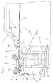
- the textile goods feed device shown in FIGS. 1 and 2 is fastened on a frame 2 which is mounted on four wheels 16 to the finishing machine, generally designated 1, not shown in detail, in which a textile material web can be shrunk, dried, fixed or cooled, to a certain extent how an attachment can be started up.
- the textile web 12 for example a knitwear, is located on a supply roll 15 and is guided from there via a tensioning tube 11, a lay-up roller 6 and a spreading spindle 7 and deflected by the latter in an approximately horizontal direction to the finishing machine.
- a tensioning tube 11 In the conveying direction A of the web behind the spreading spindle 7 there is an air-permeable, in the web conveying direction with the help of a gear motor 9 and a front deflecting roller 13 driven, endless conveyor belt on both sides of the web edge 14, above which a hood-shaped nozzle 5 is arranged, which in turn Uber a suction hose 10 is connected to a suction device 3 fastened in the movable frame 2.
- Both conveyor belts 4 and with them the hood-shaped suction nozzles 5 are directly opposite and form an adjustable angle d. to the longitudinal or conveying direction A of the web 12, are thus inclined to the conveying direction in the plane of the web.
- the distance between the opposite conveyor belts 4 is adjustable and can thus be adapted to the respective web width.
- the suction device 3 the suction effect of which is also adjustable, sucks air through the hoses 10 and the hood-shaped nozzles 5 connected to it through the conveyor belts 4, as indicated by the arrows a and b, while the conveyor belts pass over the front deflection rollers 13 and rear Move the pulleys 17 in the direction of arrow B.
- the suction of the webs on the underside of the conveyor belts while simultaneously transporting the web in the conveying direction A is done in a manner and with a force that causes the web to stretch, depending on that to the Conveyor belts adjustable inclination angle oC, whereby the web is funnel-shaped from its feed gap, which is formed by the conveyor belts 4 running over the two front deflecting rollers 13 and the counter-pressure rollers 8 opposite them, to the rear deflecting rollers 17 of the two conveyor belts to their final width which is placed on the conveyor of the finishing machine 1 by the conveyor belts 4.
- the speed of the conveyor belts can be controlled with the aid of the geared motors 9, which are electronically controlled direct current motors, in such a way that the two fabric edges 14 are transported forward at different speeds to eliminate the longitudinal warping .
- the synchronization of the conveyor speeds between the conveyor belts and the conveyor of the equipping machine takes place via a tachometer generator.
- the DC motors 9 are electronically controlled by means of a potentiometer.
- the web feed to the conveyor belts 4 is controlled by the feed roller 6, which is rubberized for this purpose, so that the web can be accomplished under tension or with a product template; the latter is particularly important for a shrinking process.
- the spreading spindle 7 arranged downstream of the feed roller has, in a manner known per se, the task of spreading and rolling out the material web before introduction into the suction area of the conveyor belts 4, that is to say to deliver it without creases.
- Through the tension tube 11 Discharge tension of the web set.
- the textile goods feeding device described here offers the possibility of material tension in both the longitudinal and transverse directions of the web and the web width, the latter by simultaneously adjusting the two conveyor belts with the associated suction elements by moving them apart or moving together while maintaining the angle cc or when changing the same by pivoting the conveyor belts with the associated suction elements about axes located in the region of the front deflection rollers 13 perpendicular to the plane of the web.
- the suction pressure in the area of the suction nozzles 5 can be adjusted not only with the aid of the suction device 3, but also by the distance of the hood-shaped suction nozzles 5 from the top of the conveyor belts 4.
- the arrangement can be such that the hood-shaped suction nozzles 5 are adjustable in height.
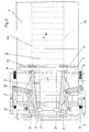
- the construction according to the invention is further characterized in that between the conveyor belt held by the vacuum generated by the suction nozzle and conveyed by the conveyor belt in the direction of the finishing machine and the rotating lower belt of the finishing machine, over the front part of which the conveyor belts extend, a sheet is arranged, which prevents direct contact of the web and the lower belt in the area of the conveyor belts.
- a sheet is arranged, which prevents direct contact of the web and the lower belt in the area of the conveyor belts.
- Above the lower belt 20 of this machine which is deflected by a deflection roller 22 at the front end of the feed table of the equipping machine 1 extends in a known manner the upper belt 18 in the running direction C, which corresponds to the running direction E of the lower belt 20 in the area in which the two belts with the goods to be equipped between them lie opposite one another.
- the feed roller 19 of the equipping machine is arranged at a comparatively small distance from the latter.
- the following parts are arranged one above the other in the order from top to bottom: the lower beam 23 of each conveyor belt 4, the web 12, the cover plate 21 and the lower belt 20 of the finishing machine.
Priority Applications (1)
| Application Number | Priority Date | Filing Date | Title |
|---|---|---|---|
| EP82102996A EP0090874A1 (fr) | 1982-04-07 | 1982-04-07 | Dispositif d'amenée de matières textiles dans une machine de finissage |
Applications Claiming Priority (1)
| Application Number | Priority Date | Filing Date | Title |
|---|---|---|---|
| EP82102996A EP0090874A1 (fr) | 1982-04-07 | 1982-04-07 | Dispositif d'amenée de matières textiles dans une machine de finissage |
Publications (1)
| Publication Number | Publication Date |
|---|---|
| EP0090874A1 true EP0090874A1 (fr) | 1983-10-12 |
Family
ID=8188975
Family Applications (1)
| Application Number | Title | Priority Date | Filing Date |
|---|---|---|---|
| EP82102996A Withdrawn EP0090874A1 (fr) | 1982-04-07 | 1982-04-07 | Dispositif d'amenée de matières textiles dans une machine de finissage |
Country Status (1)
| Country | Link |
|---|---|
| EP (1) | EP0090874A1 (fr) |
Citations (6)
| Publication number | Priority date | Publication date | Assignee | Title |
|---|---|---|---|---|
| FR1321175A (fr) * | 1961-04-26 | 1963-03-15 | Polymark Int Ltd | Perfectionnements aux appareils permettant de manipuler des articles plats en blanchisserie |
| FR2159923A5 (fr) * | 1971-11-04 | 1973-06-22 | Suntex Ltd | |
| FR2319733A1 (fr) * | 1975-07-26 | 1977-02-25 | Buettner Schilde Haas Ag | Dispositif de traitement de nappes de matiere |
| DE2647963A1 (de) * | 1976-10-22 | 1978-04-27 | Brueckner Apparatebau Gmbh | Vorrichtung zur aufgabe einer bewegten warenbahn auf ein transportorgan |
| US4140574A (en) * | 1978-03-24 | 1979-02-20 | Beloit Corporation | Web spreader and guide |
| EP0016653A1 (fr) * | 1979-03-22 | 1980-10-01 | Nippon Petrochemicals Company Limited | Procédé et dispositif pour l'étirage latéral d'une pellicule ou d'une bande fibreuse |
-
1982
- 1982-04-07 EP EP82102996A patent/EP0090874A1/fr not_active Withdrawn
Patent Citations (6)
| Publication number | Priority date | Publication date | Assignee | Title |
|---|---|---|---|---|
| FR1321175A (fr) * | 1961-04-26 | 1963-03-15 | Polymark Int Ltd | Perfectionnements aux appareils permettant de manipuler des articles plats en blanchisserie |
| FR2159923A5 (fr) * | 1971-11-04 | 1973-06-22 | Suntex Ltd | |
| FR2319733A1 (fr) * | 1975-07-26 | 1977-02-25 | Buettner Schilde Haas Ag | Dispositif de traitement de nappes de matiere |
| DE2647963A1 (de) * | 1976-10-22 | 1978-04-27 | Brueckner Apparatebau Gmbh | Vorrichtung zur aufgabe einer bewegten warenbahn auf ein transportorgan |
| US4140574A (en) * | 1978-03-24 | 1979-02-20 | Beloit Corporation | Web spreader and guide |
| EP0016653A1 (fr) * | 1979-03-22 | 1980-10-01 | Nippon Petrochemicals Company Limited | Procédé et dispositif pour l'étirage latéral d'une pellicule ou d'une bande fibreuse |
Similar Documents
| Publication | Publication Date | Title |
|---|---|---|
| EP0725178B1 (fr) | Procédé et dispositif de séchage et de rétrécissement d'étoffe textile | |
| EP0063801A1 (fr) | Dispositif pour empiler des objets plats | |
| DE2657789A1 (de) | Einrichtung zum einziehen einer papierbahn in den falzapparat einer rotationsdruckmaschine | |
| DE2711850C3 (de) | Vorrichtung zum Zick-Zack-Falten einer Stoffbahn | |
| EP0780332B1 (fr) | Dispositif pour agir sur des feuilles dans un appareil de sortie de feuilles | |
| DE2318243C2 (de) | Verfahren und Vorrichtung zum Breitstrecken und Korrigieren von Stoffbahnen | |
| DE2812579C2 (de) | Vorrichtung zum Einführen des freien Endes einer kontinuierlich geförderten Kunststoffbahn in eine Streck- und Fixierstation | |
| DE1145133B (de) | Zufuehr- und Ausspannvorrichtung fuer langgestreckte Waeschestuecke, wie Bettuecher u. dgl., zu einer Buegelmaschine | |
| EP0806346B1 (fr) | Machine d'emballage équipée d'un système pour former un tube | |
| EP0090874A1 (fr) | Dispositif d'amenée de matières textiles dans une machine de finissage | |
| DE3308069A1 (de) | Vorrichtung zum zusammenfuehren von teilbahnen ueber umlenkwalzen in eine gemeinsame ebene | |
| DE19757978A1 (de) | Vorrichtung zum Einziehen einer Warenbahn | |
| DE3212836A1 (de) | Textilwarenzufuehrvorrichtung fuer ausruestmaschinen | |
| DE4001740C2 (de) | Vorrichtung zum Auslegen einer Warenbahn | |
| DE3737674C2 (fr) | ||
| DE2838410C2 (de) | Stofflegemaschine | |
| DE2731632A1 (de) | Vorrichtung zur einzelblattentnahme von der unterseite eines blattstapels, insbesondere eines zuschnittstapels fuer die tabakverarbeitende industrie | |
| DE3001729A1 (de) | Stofflegemaschine | |
| CH682912A5 (de) | Vorrichtung zum Zuführen von Faserbändern zu einer textilverarbeitenden Maschine. | |
| CH423205A (de) | Maschine zur Behandlung einer Materialbahn, beispielsweise durch Thermoschweissung und Zerschneiden, insbesondere zur Herstellung von Säcken | |
| DE2751722C2 (de) | Verfahren und Vorrichtung zum Zuführen von Wäschestücken oder ähnlichen Textiistücken zu einer Mangel o.dgl | |
| DE270938C (fr) | ||
| WO1993024692A1 (fr) | Procede de fabrication de non-tisses, ainsi que plisseur transversal | |
| DE2325469C3 (de) | Vorrichtung zum Verkleben textiler Flächengebilde | |
| DE10255171A1 (de) | Maschine zum Schleifen der Kanten von hochkant stehendem Flachglas |
Legal Events
| Date | Code | Title | Description |
|---|---|---|---|
| PUAI | Public reference made under article 153(3) epc to a published international application that has entered the european phase |
Free format text: ORIGINAL CODE: 0009012 |
|
| AK | Designated contracting states |
Designated state(s): AT BE CH DE FR GB IT LI LU NL SE |
|
| STAA | Information on the status of an ep patent application or granted ep patent |
Free format text: STATUS: THE APPLICATION IS DEEMED TO BE WITHDRAWN |
|
| 18D | Application deemed to be withdrawn |
Effective date: 19840613 |
|
| RIN1 | Information on inventor provided before grant (corrected) |
Inventor name: EHEMANN, GERO |