EP0087739A1 - Schalungsring für Schalungen für Rundbauten - Google Patents
Schalungsring für Schalungen für Rundbauten Download PDFInfo
- Publication number
- EP0087739A1 EP0087739A1 EP83101725A EP83101725A EP0087739A1 EP 0087739 A1 EP0087739 A1 EP 0087739A1 EP 83101725 A EP83101725 A EP 83101725A EP 83101725 A EP83101725 A EP 83101725A EP 0087739 A1 EP0087739 A1 EP 0087739A1
- Authority
- EP
- European Patent Office
- Prior art keywords
- formwork
- steel strips
- ring
- butt
- steel
- Prior art date
- Legal status (The legal status is an assumption and is not a legal conclusion. Google has not performed a legal analysis and makes no representation as to the accuracy of the status listed.)
- Granted
Links
- 238000009416 shuttering Methods 0.000 title abstract 5
- 238000010276 construction Methods 0.000 title description 2
- 229910000831 Steel Inorganic materials 0.000 claims abstract description 42
- 239000010959 steel Substances 0.000 claims abstract description 42
- 238000009415 formwork Methods 0.000 claims description 33
- 229910001294 Reinforcing steel Inorganic materials 0.000 description 2
- 230000009194 climbing Effects 0.000 description 1
- 239000011150 reinforced concrete Substances 0.000 description 1
Images

Classifications
-
- E—FIXED CONSTRUCTIONS
- E04—BUILDING
- E04G—SCAFFOLDING; FORMS; SHUTTERING; BUILDING IMPLEMENTS OR AIDS, OR THEIR USE; HANDLING BUILDING MATERIALS ON THE SITE; REPAIRING, BREAKING-UP OR OTHER WORK ON EXISTING BUILDINGS
- E04G11/00—Forms, shutterings, or falsework for making walls, floors, ceilings, or roofs
- E04G11/36—Forms, shutterings, or falsework for making walls, floors, ceilings, or roofs for floors, ceilings, or roofs of plane or curved surfaces end formpanels for floor shutterings
- E04G11/48—Supporting structures for shutterings or frames for floors or roofs
- E04G11/50—Girders, beams, or the like as supporting members for forms
- E04G11/52—Girders, beams, or the like as supporting members for forms of several units arranged one after another
-
- E—FIXED CONSTRUCTIONS
- E04—BUILDING
- E04G—SCAFFOLDING; FORMS; SHUTTERING; BUILDING IMPLEMENTS OR AIDS, OR THEIR USE; HANDLING BUILDING MATERIALS ON THE SITE; REPAIRING, BREAKING-UP OR OTHER WORK ON EXISTING BUILDINGS
- E04G11/00—Forms, shutterings, or falsework for making walls, floors, ceilings, or roofs
- E04G11/06—Forms, shutterings, or falsework for making walls, floors, ceilings, or roofs for walls, e.g. curved end panels for wall shutterings; filler elements for wall shutterings; shutterings for vertical ducts
- E04G11/062—Forms for curved walls
-
- E—FIXED CONSTRUCTIONS
- E04—BUILDING
- E04G—SCAFFOLDING; FORMS; SHUTTERING; BUILDING IMPLEMENTS OR AIDS, OR THEIR USE; HANDLING BUILDING MATERIALS ON THE SITE; REPAIRING, BREAKING-UP OR OTHER WORK ON EXISTING BUILDINGS
- E04G17/00—Connecting or other auxiliary members for forms, falsework structures, or shutterings
- E04G17/002—Workplatforms, railings; Arrangements for pouring concrete, attached to the form
Definitions
- the invention relates to a formwork ring for formwork for circular buildings, consisting of ring segments which can be connected to one another, for example by means of screws.
- the invention is concerned with sliding formwork, the formwork panels, which are fastened to a sliding frame, being able to be pulled up on a climbing frame or the like in accordance with the respective construction progress.
- the object of the invention is to provide a formwork ring consisting of ring segments, the ring segments being able to be adapted to any desired formwork or building diameter.
- the circular shape of the formwork ring should be ensured.
- the steel strips are bi-steel strips.
- Bi-steel is currently used as reinforcing steel for reinforced concrete structures.
- a description of bi-steel is given, for example, in Austrian Patents Nos. 178,716 and 181,066.
- one includes a reinforcing steel which consists of at least two longitudinal bars connected to one another at a distance by cross connectors, the longitudinal bars being made of a steel with high tensile strength, and the cross connectors, which are preferably steel with a low C and / or Mn content, between the longitudinal bars are welded in.
- An embodiment of the invention provides that the inner steel strips, preferably bi-steel strips, are inseparably connected to the butt flanges, preferably welded, and the outer steel strips are held displaceably on butt flanges, for example clamped to them.
- the ring segment can be curved more or less easily in a simple manner.
- outer steel strips are held clamped to the butt flange only at one end of a ring segment, while they are welded to the butt flange on the other side.
- the outer steel strips are advantageously clamped by means of screws to webs or pins of the butt flanges.
- Another embodiment of the invention provides that the butt flanges on at least one end of a ring segment is preceded by a molded tube to which the inner and outer steel strips are connected, the inner steel strips preferably being welded on and the outer steel strips preferably being clamped by means of screws.
- Holding boards for the formwork boards are advantageously screwed to the butt flanges.
- FIG. 1 schematically shows a vertical section through a sliding formwork with a formwork ring according to the invention
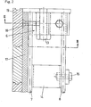
- FIG. 2 shows a plan view of the joint area of a ring segment according to the invention
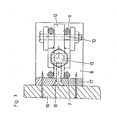
- FIG. 3 shows a section along the line III-III of FIG. 2.
- Fig. 1 only the section of the wall of the rotunda is shown. I denotes the inside of the rotunda and A the outside of the rotunda.
- the entire sliding formwork 1 and thus the formwork rings 2 extend around the entire circumference of the rotunda, which is defined by the inner radius ri and the outer radius ra.
- formwork rings 2 are provided over the height of the sliding formwork, but the number of formwork rings can vary.
- the entire sliding formwork 1 is fastened to a sliding frame 3 and can be pulled up on one column or several columns 4.
- the outer formwork 1 is fastened to the inner formwork or to the sliding frame 3 by means of a gallows 5.
- the particular details of this sliding formwork 1 with respect to scaffolding and relocability should not be dealt with in this context, since it is not part of the subject matter of the invention and after conventional state of the art can be solved.
- the formwork rings 2 are composed of several ring segments, each of which has a butt flange 6 at both ends.
- the steel strips 7 and 8 which are radially distanced from one another, extend between the abutment flanges 6.
- bi-steel strips are used.
- the outer bi-steel strips 8 are clamped to a web 12 of the butt flange 6 by means of screws 10 and nuts 11.
- this embodiment provides a certain length of the ring segments, the curvature of the ring segments can be changed by moving the clamping point on the bi-steel strip 8.
- shaped tubes 14 are arranged in front of the butt flanges 6 in the ring segments, the inner bi-steel band 7 being in turn welded to the shaped tube 14, while the outer bi-steel band 8 is fastened to the by means of a screw 15 Form tube is clamped.
- This design resulted in better dimensional stability of the ring segments.
- vertical struts can again be provided in the form of a molded tube; such a strut 16 is advantageous only with every second or third butt flange 6, ie every second or third connection point of two ring segments can be provided.
- holding boards 17 are screwed onto the butt flanges 6 by means of screws 18.
- the formwork boards 19 are then nailed to the holding boards 17.
- the 1 also has 20 working platforms, which can be designed as such according to the prior art;
- the work platforms 20 are advantageously fastened to the ring segments 2 of the formwork according to the invention.
Landscapes
- Engineering & Computer Science (AREA)
- Architecture (AREA)
- Mechanical Engineering (AREA)
- Civil Engineering (AREA)
- Structural Engineering (AREA)
- Forms Removed On Construction Sites Or Auxiliary Members Thereof (AREA)
Abstract
Description
- Die Erfindung bezieht sich auf einen Schalungsring für Schalungen für Rundbauten, bestehend aus Ringsegmenten, die miteinander, beispielsweise mittels Schrauben, verbindbar sind. Insbesondere beschäftigt sich die Erfindung mit Gleitschalungen, wobei die Schaltafeln, die auf einem Gleitgerüst befestigt sind, an einem Klettergerüst od. dgl. entsprechend dem jeweiligen Baufortschritt hochgezogen werden können.
- Aufgabe der Erfindung ist es, einen Schalungsring, bestehend aus Ringsegmenten, zu schaffen, wobei sich die Ringsegmente jedem gewünschten Schalungs- bzw. Gebäudedurchmesser anpassen lassen. Insbesondere soll die Kreisform des. Schalungsringes gewährleistet sein.
- Dies wird erfindungsgemäß erreicht durch zwei radial distanzierte Stahlbänder der Ringsegmente, die mit Stoßflanschen verbunden sind.
- Vorteilhaft ist vorgesehen, daß die Stahlbänder Bi-Stahlbänder sind.
- Bi-Stahl findet zur Zeit als Bewehrungsstahl für Stahlbetonkonstruktionen Verwendung. Eine Beschreibung von Bi-Stahl ist beispielsweise in den österr. Patenten Nr. 178.716 und 181.066 gegeben. Grundsätzlich versteht man darunter einen Bewehrungsstahl, welcher aus mindestens zwei miteinander in Abstand durch Querverbinder verbundenen Längsstäben besteht, wobei die Längsstäbe aus einem Stahl hoher Streckfestigkeit bestehen,und die Querverbinder, die vorzugsweise Stahl mit niedrigem C-und/oder Mn-Gehalt sind, zwischen den Längsstäben eingeschweißt sind.
- Einer der besonderen Vorteile des Bi-Stahles, abgesehen von seiner hohen Belastbarkeit, ist darin zu sehen, daß der Bi-Stahl, wie beobachtet werden kann, wenn er gebogen wird selbsttätig den Biegungsverlauf einer Kreiskurve annimmt.
- Ein Ausführungsbeispiel der Erfindung sieht vor, daß die inneren Stahlbänder,vorzugsweise Bi-Stahlbänder, mit den Stoßflanschen unlösbar verbunden, vorzugsweise verschweißt sind, und die äußeren Stahlbänder versetzbar an Stoßflanschen gehalten, beispielsweise an diese geklemmt sind. Durch Versetzen der Stoßflansche an den äußeren Stahlbändern kann das Ringsegment auf einfache Weise mehr oder weniger stark gekrümmt werden.
- Ein weiteres Ausführungsbeispiel sieht vor, daß die äußeren Stahlbänder nur an einem Ende eines Ringsegmentes klemmend an dem Stoßflansch gehalten sind, während sie an der anderen Seite mit dem Stoßflansch verschweißt sind. Vorteilhaft sind die äußeren Stahlbänder mittels Schrauben an Stege oder Zapfen der Stoßflansche geklemmt.
- Ein weiteres Ausführungsbeispiel der Erfindung sieht vor, daß den Stoßflanschen an mindestens einem Ende eines Ringsegmentes ein Formrohr vorgesetzt ist, mit dem die inneren und äußeren Stahlbänder verbunden sind, wobei die inneren Stahlbänder vorzugsweise angeschweißt, und die äußeren Stahlbänder vorzugsweise mittels Schrauben angeklemmt sind.
- An die Stoßflansche sind vorteilhaft Haltebretter für die Schalbretter angeschraubt.
- Nachfolgend wird ein Ausführungsbeispiel der Erfindung anhand der Figuren der beiliegenden Zeichnungen eingehend beschrieben, ohne daß die Erfindung darauf eingeschränkt sein soll. Ebenso sollen die in den nachfolgenden Patentansprüchen angeführten Bezugszeichen keine Einschränkung bedeuten, sie dienen lediglich dem erleichterten Auffinden bezogener Teile in den Figuren der Zeichnungen.
- Die Fig. 1 zeigt schematisch einen Vertikalschnitt durch eine Gleitschalung mit erfiudungsgemäßem Schalungsring, die Fig. 2 zeigt eine Draufsicht auf den Stoßbereich eines erfindungsgemäßen Ringsegmentes,und die Fig. 3 zeigt einen Schnitt nach der Linie III-III der Fig. 2.
- In der Fig. 1 ist nur der Schnittbereich der Wand des Rundbaues gezeigt. Mit I ist das Innere des Rundbaues und mit A das Äußere des Rundbaues bezeichnet. Die gesamte Gleitschalung 1 und somit die Schalungsringe 2 erstrecken sich um den gesamten Umfang des Rundbaues, der jeweils vom Innenradius ri und vom Außenradius ra definiert wird.
- Im Ausführungsbeispiel sind über die Höhe der Gleitschalung 4 Schalungsringe 2 vorgesehen, die Anzahl der Schalungsringe kann jedoch variieren.
- Die gesamte Gleitschalung 1 ist an einem Gleitgerüst 3 befestigt und kann an einer Säule oder mehreren Säulen 4 hochgezogen werden. Die äußere Schalung 1 ist mittels eines Galgens 5 an der inneren Schalung bzw. am Gleitgerüst 3 befestigt. Auf die besonderen Einzelheiten dieser Gleitschalung 1 in bezug auf Gerüst und Versetzbarkeit soll in diesem Rahmen nicht eingegangen werden, da es nicht zum Gegenstand der Erfindung gehört und nach herkömmlichem Stand der Technik gelöst werden kann.
- Die Schalungsringe 2 setzen sich aus mehreren Ringsegmenten zusammen, die an ihren beiden Enden jeweils einen Stoßflansch 6 aufweisen. Zwischen den Stoßflanschen 6 erstrecken sich die Stahlbänder 7 und 8, die voneinander radial distanziert sind. Im Ausführungsbeispiel werden Bi-Stahlbänder verwendet.
- Im Ausführungsbeispiel sind die inneren Bi-Stahlbänder 7, d.h. die Bi-Stahlbänder, die sich näher zur Schalungswand und somit zur Mauer 9 befinden, an die Stoßflansche 6 angeschweißt. Die äußeren Bi-Stahlbänder 8 sind mittels Schrauben 10 und Muttern 11 an einem Steg 12 des Stoßflansches 6 geklemmt.
- Durch diese Ausführung ist zwar eine gewisse Länge der Ringsegmente gegeben, die Krümmung der Ringsegmente kann jedoch durch Versetzen der Klemmstelle an dem Bi-Stahlband 8 verändert werden.
- Zur Herstellung eines Schalungsringes 2 werden die Stoßflansche 6 mittels Schrauben und Muttern 13 miteinander verschraubt.
- Wie aus der Fig. 2 ersichtlich, sind im Ausführungsbeispiel vor den Stoßflanschen 6 bei den Ringsegmenten Formrohre 14 angeordnet, wobei das innere Bi-Stahlband 7 wiederum mit dem Formrohr 14 verschweißt ist, während das äußere Bi-Stahlband 8 mittels einer Schraube 15 an das Formrohr geklemmt wird. Durch diese Ausführung ergab sich eine bessere Formstabilität der Ringsegmente.
- Zusätzlich können noch, wie in der Fig. 1 unter 16 gezeigt, vertikale Verstrebungen in der Form wiederum eines Formrohres vorgesehen sein; eine derartige Verstrebung 16 wird jedoch vorteilhaft nur bei jedem zweiten oder dritten Stoßflansch 6, d.h. bei jeder zweiten oder dritten Verbindungsstelle zweier Ringsegmente vorgesehen sein.
- Wie aus den Fig. 3 und 4 ersichtlich, sind Haltebretter 17 mittels Schrauben 18 an die Stoßflansche 6 angeschraubt. An die Haltebretter 17 sind dann die Schalbretter 19 angenagelt.
- In der Fig. 1 sind noch mit 20 Arbeitsbühnen eingezeichnet, die als solche gemäß dem Stand der Technik ausgeführt sein können; vorteilhaft sind die Arbeitsbühnen 20 an den erfindungsgemäßen Ringsegmenten 2 der Schalung befestigt.
Claims (7)
Applications Claiming Priority (2)
| Application Number | Priority Date | Filing Date | Title |
|---|---|---|---|
| AT0078882A AT399009B (de) | 1982-03-02 | 1982-03-02 | Schalungsring für schalungen für rundbauten |
| AT788/82 | 1982-03-02 |
Publications (2)
| Publication Number | Publication Date |
|---|---|
| EP0087739A1 true EP0087739A1 (de) | 1983-09-07 |
| EP0087739B1 EP0087739B1 (de) | 1986-11-12 |
Family
ID=3499763
Family Applications (1)
| Application Number | Title | Priority Date | Filing Date |
|---|---|---|---|
| EP83101725A Expired EP0087739B1 (de) | 1982-03-02 | 1983-02-23 | Schalungsring für Schalungen für Rundbauten |
Country Status (3)
| Country | Link |
|---|---|
| EP (1) | EP0087739B1 (de) |
| AT (1) | AT399009B (de) |
| DE (1) | DE3367644D1 (de) |
Cited By (1)
| Publication number | Priority date | Publication date | Assignee | Title |
|---|---|---|---|---|
| CN111453065A (zh) * | 2020-05-07 | 2020-07-28 | 唐山佳捷包装机械制造有限公司 | 一种纸箱包装翻箱设备 |
Citations (4)
| Publication number | Priority date | Publication date | Assignee | Title |
|---|---|---|---|---|
| AT178716B (de) * | 1959-06-24 | 1954-06-10 | Evg Entwicklung Verwert Ges | Bewehrungsstahl für Stahlbetonkonstruktionen und Gitterwerk aus diesem |
| BE721258A (de) * | 1967-09-29 | 1969-03-03 | ||
| FR2226522A1 (en) * | 1973-04-18 | 1974-11-15 | Koch Anc Ets Rieger Sa Ets | Adjustably curved steel beam - has longitudinal strips clamped to tops of vert. webs of bottom flange |
| DE3122298A1 (de) * | 1980-06-06 | 1982-03-25 | Tosco Corp., 90067 Los Angeles, Calif. | Verfahren zur entfernung von stickstoffoxid aus gasstroemen |
-
1982
- 1982-03-02 AT AT0078882A patent/AT399009B/de not_active IP Right Cessation
-
1983
- 1983-02-23 DE DE8383101725T patent/DE3367644D1/de not_active Expired
- 1983-02-23 EP EP83101725A patent/EP0087739B1/de not_active Expired
Patent Citations (4)
| Publication number | Priority date | Publication date | Assignee | Title |
|---|---|---|---|---|
| AT178716B (de) * | 1959-06-24 | 1954-06-10 | Evg Entwicklung Verwert Ges | Bewehrungsstahl für Stahlbetonkonstruktionen und Gitterwerk aus diesem |
| BE721258A (de) * | 1967-09-29 | 1969-03-03 | ||
| FR2226522A1 (en) * | 1973-04-18 | 1974-11-15 | Koch Anc Ets Rieger Sa Ets | Adjustably curved steel beam - has longitudinal strips clamped to tops of vert. webs of bottom flange |
| DE3122298A1 (de) * | 1980-06-06 | 1982-03-25 | Tosco Corp., 90067 Los Angeles, Calif. | Verfahren zur entfernung von stickstoffoxid aus gasstroemen |
Cited By (1)
| Publication number | Priority date | Publication date | Assignee | Title |
|---|---|---|---|---|
| CN111453065A (zh) * | 2020-05-07 | 2020-07-28 | 唐山佳捷包装机械制造有限公司 | 一种纸箱包装翻箱设备 |
Also Published As
| Publication number | Publication date |
|---|---|
| ATA78882A (de) | 1994-07-15 |
| AT399009B (de) | 1995-03-27 |
| DE3367644D1 (en) | 1987-01-02 |
| EP0087739B1 (de) | 1986-11-12 |
Similar Documents
| Publication | Publication Date | Title |
|---|---|---|
| DE2406904A1 (de) | Schalung fuer rundbehaelter | |
| DE102017218783A1 (de) | Stütze zum Abstützen eines Bauwerksbereichs | |
| EP0694659B1 (de) | Traggerüst | |
| EP0098962B1 (de) | Montagegerüst für Schalungen für Rundbauten aus Beton od.dgl. | |
| EP2455305A1 (de) | Silo | |
| DE3214625C2 (de) | Balkenförmiger Ausleger, insbesondere als Sprührahmen für Pflanzenschutzgeräte | |
| WO1986004378A1 (fr) | Coffrage segmente pour constructions circulaires | |
| EP0087739B1 (de) | Schalungsring für Schalungen für Rundbauten | |
| DE19946060A1 (de) | Verfahren und Vorrichtung zur Erhöhung und/oder Sanierung von Masten | |
| EP0112861A1 (de) | Innenschalung für rotationssymmetrische Bauten. | |
| DE3231220C2 (de) | Klammer zum Verbinden einander kreuzender Träger | |
| EP0637661A2 (de) | Schalung zur Herstellung von Betonrundsäulen | |
| AT233810B (de) | Schalungseinheit mit elastischen Schaltafeln | |
| DE6921153U (de) | Saeulenschalung | |
| DE1534916C2 (de) | Vorgefertigte Schalung fur Pilz decken | |
| DE2927743A1 (de) | Freitragende treppe | |
| DE20320097U1 (de) | Zelt | |
| DE2428599C3 (de) | Lehre zum Aufbringen von Verputz | |
| DE1027613B (de) | Vorrichtung zum Abstuetzen der Firste von Grubenstrecken | |
| DE1888634U (de) | Absperrgeländer aus Stützen und daran angeschlossenen Oberstreben und Zwischenstreben aus Rohren | |
| DE3639697A1 (de) | Geruest, insbesondere baugeruest | |
| DE2919107A1 (de) | Teilbarer mast bzw. teilbare saeule | |
| DE1941737A1 (de) | Aus mehreren,auf Abstand voneinander verlegten Traegern bestehende Tragkonstruktion,insbesondere fuer Daecher | |
| DE2109375A1 (de) | Bewehrungselement | |
| DE1684241B2 (de) | Gleitschalung für Baukonstruktionen |
Legal Events
| Date | Code | Title | Description |
|---|---|---|---|
| PUAI | Public reference made under article 153(3) epc to a published international application that has entered the european phase |
Free format text: ORIGINAL CODE: 0009012 |
|
| AK | Designated contracting states |
Designated state(s): BE CH DE FR GB IT LI NL SE |
|
| 17P | Request for examination filed |
Effective date: 19840306 |
|
| GRAA | (expected) grant |
Free format text: ORIGINAL CODE: 0009210 |
|
| AK | Designated contracting states |
Kind code of ref document: B1 Designated state(s): BE CH DE FR GB IT LI NL SE |
|
| PG25 | Lapsed in a contracting state [announced via postgrant information from national office to epo] |
Ref country code: SE Effective date: 19861130 |
|
| REF | Corresponds to: |
Ref document number: 3367644 Country of ref document: DE Date of ref document: 19870102 |
|
| ITF | It: translation for a ep patent filed | ||
| PGFP | Annual fee paid to national office [announced via postgrant information from national office to epo] |
Ref country code: NL Payment date: 19870228 Year of fee payment: 5 |
|
| ET | Fr: translation filed | ||
| REG | Reference to a national code |
Ref country code: CH Ref legal event code: PUE Owner name: ERNST BOSSHARD |
|
| PLBE | No opposition filed within time limit |
Free format text: ORIGINAL CODE: 0009261 |
|
| STAA | Information on the status of an ep patent application or granted ep patent |
Free format text: STATUS: NO OPPOSITION FILED WITHIN TIME LIMIT |
|
| REG | Reference to a national code |
Ref country code: FR Ref legal event code: TP |
|
| 26N | No opposition filed | ||
| PG25 | Lapsed in a contracting state [announced via postgrant information from national office to epo] |
Ref country code: LI Effective date: 19880229 Ref country code: CH Effective date: 19880229 |
|
| BERE | Be: lapsed |
Owner name: PATENVER A.G. Effective date: 19880228 |
|
| PG25 | Lapsed in a contracting state [announced via postgrant information from national office to epo] |
Ref country code: NL Effective date: 19880901 |
|
| NLV4 | Nl: lapsed or anulled due to non-payment of the annual fee | ||
| REG | Reference to a national code |
Ref country code: CH Ref legal event code: PL |
|
| PG25 | Lapsed in a contracting state [announced via postgrant information from national office to epo] |
Ref country code: BE Effective date: 19890228 |
|
| REG | Reference to a national code |
Ref country code: GB Ref legal event code: 732 |
|
| PGFP | Annual fee paid to national office [announced via postgrant information from national office to epo] |
Ref country code: GB Payment date: 20010221 Year of fee payment: 19 |
|
| PGFP | Annual fee paid to national office [announced via postgrant information from national office to epo] |
Ref country code: FR Payment date: 20010227 Year of fee payment: 19 |
|
| PGFP | Annual fee paid to national office [announced via postgrant information from national office to epo] |
Ref country code: DE Payment date: 20010308 Year of fee payment: 19 |
|
| REG | Reference to a national code |
Ref country code: GB Ref legal event code: 732E |
|
| REG | Reference to a national code |
Ref country code: GB Ref legal event code: IF02 |
|
| PG25 | Lapsed in a contracting state [announced via postgrant information from national office to epo] |
Ref country code: GB Free format text: LAPSE BECAUSE OF NON-PAYMENT OF DUE FEES Effective date: 20020223 |
|
| REG | Reference to a national code |
Ref country code: FR Ref legal event code: TP |
|
| REG | Reference to a national code |
Ref country code: FR Ref legal event code: TP |
|
| PG25 | Lapsed in a contracting state [announced via postgrant information from national office to epo] |
Ref country code: DE Free format text: LAPSE BECAUSE OF NON-PAYMENT OF DUE FEES Effective date: 20020903 |
|
| GBPC | Gb: european patent ceased through non-payment of renewal fee |
Effective date: 20020223 |
|
| PG25 | Lapsed in a contracting state [announced via postgrant information from national office to epo] |
Ref country code: FR Free format text: LAPSE BECAUSE OF NON-PAYMENT OF DUE FEES Effective date: 20021031 |
|
| REG | Reference to a national code |
Ref country code: FR Ref legal event code: ST |