EP0085418A2 - Procédé et installation pour appliquer des étiquettes auto-adhésives - Google Patents
Procédé et installation pour appliquer des étiquettes auto-adhésives Download PDFInfo
- Publication number
- EP0085418A2 EP0085418A2 EP83100832A EP83100832A EP0085418A2 EP 0085418 A2 EP0085418 A2 EP 0085418A2 EP 83100832 A EP83100832 A EP 83100832A EP 83100832 A EP83100832 A EP 83100832A EP 0085418 A2 EP0085418 A2 EP 0085418A2
- Authority
- EP
- European Patent Office
- Prior art keywords
- label
- support roller
- speed
- point
- carrier tape
- Prior art date
- Legal status (The legal status is an assumption and is not a legal conclusion. Google has not performed a legal analysis and makes no representation as to the accuracy of the status listed.)
- Withdrawn
Links
Images
Classifications
-
- B—PERFORMING OPERATIONS; TRANSPORTING
- B65—CONVEYING; PACKING; STORING; HANDLING THIN OR FILAMENTARY MATERIAL
- B65C—LABELLING OR TAGGING MACHINES, APPARATUS, OR PROCESSES
- B65C9/00—Details of labelling machines or apparatus
- B65C9/0006—Removing backing sheets
-
- B—PERFORMING OPERATIONS; TRANSPORTING
- B65—CONVEYING; PACKING; STORING; HANDLING THIN OR FILAMENTARY MATERIAL
- B65C—LABELLING OR TAGGING MACHINES, APPARATUS, OR PROCESSES
- B65C9/00—Details of labelling machines or apparatus
- B65C9/08—Label feeding
- B65C9/18—Label feeding from strips, e.g. from rolls
- B65C9/1865—Label feeding from strips, e.g. from rolls the labels adhering on a backing strip
- B65C9/1869—Label feeding from strips, e.g. from rolls the labels adhering on a backing strip and being transferred directly from the backing strip onto the article
-
- B—PERFORMING OPERATIONS; TRANSPORTING
- B65—CONVEYING; PACKING; STORING; HANDLING THIN OR FILAMENTARY MATERIAL
- B65C—LABELLING OR TAGGING MACHINES, APPARATUS, OR PROCESSES
- B65C9/00—Details of labelling machines or apparatus
- B65C9/40—Controls; Safety devices
- B65C9/42—Label feed control
Definitions
- the invention relates to a method for applying self-adhesive, adhering to a carrier tape and detachable at a deflection point of the carrier tape on labels pushed at mutually spaced objects with a certain object speed, in which the carrier tape feeds the labels with a certain label speed and each at a point of impact Label is applied to an object in the correct position.
- the invention further relates to a device for performing this method.
- a device suitable for carrying out this method according to the invention is the subject of claims 3 and 4.
- the label tape carrying the labels is driven continuously at a speed which is at least over a part of the feed length in accordance with the distance between two successive objects and in accordance with their speed, as well as the distance of the labels from one another and to the point of impact Label leading edge on the object still to be covered distance of the objects and the labels is determined.
- This determination is made by an electronic computer.
- This label speed can be in every single work cycle, i. H. with respect to each object to be labeled, can be newly determined and defined, as a result of which the labels can be placed on the objects extremely precisely and at high speed.
- the possibly required change in the feed speed of the label tape can also be carried out in accordance with an averaging over several work cycles, if an exact placement of the labels is not so important. In this way, tax advantages are achieved.
- the speed of the label tape is thus determined so that even if the object speed at the dispensing point of the label varies and / or if the distance between these objects varies, the label speed is changed so that, on the one hand, the machine stops Feed of the label tape does not occur as far as possible and on the other hand the label detaches itself from the carrier tape at exactly the point in time that is required for an exact label placement.
- the speed at which the objects to be labeled are moved on the detected path and by comparing the mutual distance of these objects and the labels from the dispensing point or, which means the same, by detecting the object and the label at the moment in Since this occurs in a certain area, namely the detected distance between the reference point and the point of impact, the speed at which the label tape must be advanced is calculated in order to prevent the label tape from coming to a standstill and to ensure that the label arrives at the dispensing point with the correct timing .
- the label speed can be determined for the entire distance covered. However, the label speed can also be determined only for a part of this distance, the remaining part of this distance at a predetermined speed is run through, which corresponds, for example, to the article speed at the dispensing point, so that the label has the same speed as the article to be labeled during its detachment from the carrier tape and the simultaneous application on the article in many applications.
- the label speed at the dispensing point is lower than the object speed, the label is additionally pulled off the carrier tape by the object moving at a higher speed.
- the label speed is not constant on the first part of the path, but adapts at the beginning and / or end of this path to the speed with which the tape carrying the labels is driven in the subsequent feed section.
- the invention makes it possible to move the label strip continuously, and with appropriate programming of the computer it can be excluded that extremely rapid changes in the feed rate occur.
- the individual label speed on the detected path is varied so that the initial speed adapts to the label speed at the end of the previous work cycle without a sudden transition, after which, after running through any speed sequence controlled by the computer, a speed is reached at the end of this section of the work cycle , which corresponds to the speed of the label tape provided in the following section of the working cycle.
- These gentle speed changes controlled by the computer prevent the carrier tape from being excessively stressed by inertial forces.
- a device which divides a distance lying in front of the dispensing point and reaching as far as a reference point into many small sections or increments.
- a clock generator sends object location pulses to the computer.
- the computer recognizes at any moment on which section of the transport route the object to be labeled is located.
- These impulses can be given, for example, by a driver who brings the objects to the point of impact and transported beyond.
- the pulses can be generated photoelectrically.
- a partially translucent and partially opaque rotating disk driven by the conveyor belt of the objects is particularly suitable, the light pulses being converted into electrical pulses in a known manner by a photocell.
- the device according to the invention also has a device for generating a reference pulse which marks the entry of the object into the detected path.
- This reference pulse can be generated, for example, by a light barrier, which triggers the pulse through the front edge of the object to be labeled when it enters the detected path.
- the device may also include means for determining the distance between the location at which the reference pulse is triggered and the location that the leading edge of the object must have reached when the leading edge of the label is at a predetermined point of impact of the object hits.
- This means may be a digitally t ale setting millimeters display, the display is calibrated so as to indicate the distance of the impact point of the leading edge of the label from the leading edge of the article.
- the device also contains a device which emits label location pulses corresponding to the respective location of the label on a transport section of the label tape located in front of the dispensing point of the device.
- a clock generator can be used which is designed in the same way as the clock generator for the object location pulses.
- the label location pulses are fed to the computer together with a reference pulse.
- the reference pulse is generated by the entry of the front edge of the label into the detected path at a reference point.
- the distance covered extends from this reference point to the point of impact of the label on the object. The length of this distance is preferably adjustable.
- This reference pulse assigned to the label can also be generated by a photocell or another scanning device which scans the gap between the labels and the front edge of the label.
- the pulses corresponding to the local transport or W egabitese are very small.
- the increments related to the transport of the items are the same among themselves. The same applies to the increments of the label transport route.
- the label transport increments can be the same size as the item transport increments.
- the respective increments can also be of different sizes.
- the computer determines the exact position of the object or the label by counting the location pulses arriving after the reference pulse and comparing their speeds with a unit of time. The computer continuously determines the speed that is required to cover the remaining distance until the object is labeled or to reach the specified speed.
- the feed speed of the labels is much less than the speed of the objects when the ratio of transport of the labels to the transport path of the objects is considerably simplified. If the label tape moves at the same speed as the object during the application of the label, the feed speed is . speed of the label tape in the preceding transport section at the beginning of the work cycle even smaller and the Etikettenlän g e must be taken into account in the above ratio.
- the label tape is driven by a servo motor which is controlled by the computer depending on the path traveled by both the label and the object and their instantaneous locations, the servo motor being at can be fed via a transistor amplifier, for example.
- the transport sections during which location impulses are emitted coincide with the transport route which the object or the label travels during a work cycle.
- the path-dependent control of the label feed can also take place only on a part of the feed path traveled during a work cycle, irrespective of whether a section adjoins the section with path-controlled speed in which the label is moved at the transport speed of the objects or not.
- this transport route beginning with a reference pulse also coincides with the start of a work cycle.
- the reference pulses signal that the object and the label have reached a very specific position in the labeling device at a certain point in time.
- this deflection edge in order to avoid frictional losses, consists of a pin with small diameter, which is mounted in ball bearings and over which the carrier tape is guided.
- This embodiment of the invention can be further developed in that a support roller is arranged at the dispensing point and the carrier tape is guided between the support roller and the deflection pin.
- the support roller is arranged in such a way that the deflection pin can be supported on the circumference of the support roller through the band carrying the labels. This makes it possible to use pins with a very small diameter, which would bend without a support roller under the load caused by the carrier tape being pulled off under tension.
- the deflection pin is supported on two support rollers which are arranged in such a way that a gap remains between these rollers, but the pin is supported on both support rollers.
- the label tape is then through this gap passed between the two support rollers and then between a support roller and the pin supported on it in part, wraps around the pin, passes between the pin and the other support roller and is then returned through the gap between the two support rollers.
- the carrier tape wraps around the pin by about 18 0 0 , so that on this deflection also labels detach from the carrier tape, which have only a very low inherent rigidity.
- the diameter of the pin can be approximately 1 mm.
- the two support rollers in turn can be supported on a third support roller with a larger diameter, in which case the label tape is then passed between the larger support roller and a small support roller, and the empty carrier tape is then passed between the second small support roller and the larger support roller .
- the support rollers can be cylindrical, but they can also have only cylindrical jacket-shaped sections, between which there are sections whose outer surfaces are delimited by concave lines.
- the aforementioned support rollers can be used in other preferred ones. Embodiments of the invention are also driven, namely all support rollers or only a part of them. It is particularly advantageous to drive the aforementioned third support roller with the larger diameter alone and to have the other two support rollers entrained only by friction.
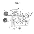
- the label tape 1 which consists of a carrier tape 2 and adhesive labels 3 adhering to it, is wound on a supply roll 4.
- the label tape 1 is pulled over a pin 5 mounted in ball bearings, which deflects the label tape so strongly that the label 3 'due to its stiffness detaches from the carrier tape 2 drawn around it by the pin 5 and from a pressure roller 6 an object 12 is rolled up.
- the drive and thus the feed of the label tape is carried out by a transport device 7 acting on the carrier tape 2 behind the deflecting edge 5, which for simplicity is drawn as a spiked roller, the spikes of which engage in holes in the carrier tape and thus produce a positive connection between the carrier tape 2 and the transport device.
- the spiked roller 7 is driven by a servo motor 8, the speed of which is controlled by a computer 10 via a line 9.
- a photoelectric device 11, 13 is installed which emits a reference signal when the front edge of a label 3 arrives at this point.
- a photoelectric device 14, 15 emits a reference signal when the front edge 16 of an object 12 to be labeled is recognized by this device.
- the objects 12 to be labeled are positively attached to a transport device 17.
- a spiked roller 18 engages positively in the transport device 17, which is positively connected via a speed-increasing connection 19 to a transparent and opaque sector disc 2o, which emits electrical impulses when the transport device 17 moves with the aid of a photoelectric device 21, 22, correspond to the small distances (increments) of the path covered by the transport device 17.
- the distance of the photoelectric device 14, 15 from the point of impact 23 at which the front edge of the label 3 'should hit the object 12 to be labeled with precise placement of the label is adjustable, it forms the "detected transport section" or the "detected distance”.
- a spiked roller 24 engages positively in holes in the label tape 1.
- a sector disk 26 corresponding to disk 20 is positively connected to it via a transmission gear 25, which generates electric pulses on line 29 via a photoelectric device 27, 28, which correspond to small distances (increments) of the route covered by labeling tape 1.
- the computer 1o thus receives via the photoelectric device 21, 22 pulses which it counts from the arrival of the reference pulse arriving on the line 3o through the photoelectric device 14, 15.
- the computer 10 also counts the pulses arriving on the line 29 through the photoelectric device 27, 28, which correspond to the path covered by the labeling tape 1, from the arrival of a reference pulse from the photoelectric device 11, 13, which on line 31 sends the computer 1o is supplied.
- the distance between the point of impact 23 of the front edge of the label 3 'on the object 12 and the photoelectric unit 14, 15, which emits the reference pulse for the transport movement of the objects to be labeled, is set on the device 33.
- the calculator 1 0 calculates the speed and the instantaneous location of the label front edge and the front edge 16 of the object 12 from the number of "location pulses" received since the associated reference pulse and corresponding to the increments.
- the computer calculates the distance between this point and the front edge of the label 3 or the front edge 16 of the object 12 and the speed that the label tape must have so that the front edge of the at the deflection edge 5th stripping label 3 'strikes the object 12 at the point of impact 23 at exactly the right time. This speed is then given via the control line 9 to the servo motor 8, which pulls the label tape 1 at the calculated speed by pulling on the carrier tape 2.
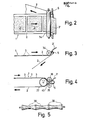
- the carrier tape 2 is pulled around a pin 5 by a drive (not shown) for detaching the label 3 ', the drive on the pin 5 away carrier tape 2 attacks.
- the pin has a diameter of about 1 to 3 mm, the carrier tape wraps around the pin so that it is deflected by about 18 0 0 .
- the pin 5 does not bend, it is supported by a rotatable support roller 34, on the circumference of which the pin 5 rests.
- the label tape 1 is passed between the support roller 34 and the pin 5.
- the label 3 'detaches from the carrier tape at the point at which it is guided around the pin 5.
- the connecting lines between the axis of the pin 5 and the axis of the support roller 34 run at the smallest possible angle to the direction of the resulting force generated on the pin 5 by the two strands of the carrier tape 2.
- Fig. 4 shows an embodiment of the invention, in which the pin 5 is supported by two rotatable support rollers 35 and 36, the diameter of which is larger than the diameter of the pin 5. These two support rollers are in turn supported on a rotatable support roller 37, the diameter of which is substantially larger than the diameter of a support roller 35, 36.
- the label tape is passed between the large support roller 37 and the small support roller 36, then passes through the gap 4o between the small support rollers 35 and 36, whereupon the carrier tape is then passed around the pin 5 with a very small diameter, the conveyor belt 2 approximately 27o 0 wraps around the circumference of the pin 5.
- the conveyor belt 2 passes between the pin 5 and the support roller 35 and then through the gap between the support rollers 35 and 36, whereupon it finally leads between the support rollers 35 and 37 to the transport device.
- the outer surface of the rollers 37, 36 and 5 lie close together, only the label tape is passed between these outer surfaces.
- the outer surfaces of the pin 5, the support roller 35 and the large support roller 37 lie close together and only the conveyor belt 2 is passed between these outer surfaces.
- the support rollers 35, 36 and 37 can have cylindrical sections 38, between which sections 39 are arranged which are not cylindrical, but whose outer surface is delimited by concave lines, as is shown in FIG. 5.
- the support rollers 35, 36 and 37 can also be mounted in ball bearings, their direction of rotation is indicated in the figures. It is also possible to drive these rollers using a friction wheel drive with low torque in the direction of the arrows. All support rollers 35, 36, 37 can be driven, or only a few. Preferably, only the support roller 37 is driven.
- the driven support rollers, in particular the support roller 37 can at the same time also take over the (frictional) drive of the label strip 1 and replace the transport device 7 in FIG. 1.
- the control line 9 leading to the computer 10 is then connected to the drive motor of the support shaft (s).
- the transport section mentioned above which is detected by the "increments" begins in Fig. 1 at the light beam of the photoelectric device 14, 15, which emits the reference pulse for the transport movement of the transport device 17, and ends at the point of impact 23.
- the transport section the label transport which is detected by the "increments" begins at the light barrier of the photoelectric device 11, 13 and also ends at the point of impact 23.
Applications Claiming Priority (2)
| Application Number | Priority Date | Filing Date | Title |
|---|---|---|---|
| DE3203162 | 1982-01-30 | ||
| DE19823203162 DE3203162A1 (de) | 1982-01-30 | 1982-01-30 | Verfahren und vorrichtung zum etikettieren von gegenstaenden |
Publications (2)
| Publication Number | Publication Date |
|---|---|
| EP0085418A2 true EP0085418A2 (fr) | 1983-08-10 |
| EP0085418A3 EP0085418A3 (fr) | 1984-08-29 |
Family
ID=6154400
Family Applications (1)
| Application Number | Title | Priority Date | Filing Date |
|---|---|---|---|
| EP83100832A Withdrawn EP0085418A3 (fr) | 1982-01-30 | 1983-01-28 | Procédé et installation pour appliquer des étiquettes auto-adhésives |
Country Status (2)
| Country | Link |
|---|---|
| EP (1) | EP0085418A3 (fr) |
| DE (1) | DE3203162A1 (fr) |
Cited By (10)
| Publication number | Priority date | Publication date | Assignee | Title |
|---|---|---|---|---|
| GB2208841A (en) * | 1987-08-13 | 1989-04-19 | New Jersey Machine Inc | Labelling system |
| FR2635503A1 (fr) * | 1987-08-13 | 1990-02-23 | New Jersey Machine Inc | Systeme et procede d'etiquetage |
| WO1994005578A1 (fr) * | 1992-09-01 | 1994-03-17 | Cms Gilbreth Packaging Systems, Inc. | Appareil et procede de raccordement automatique |
| EP0756256A1 (fr) * | 1995-07-27 | 1997-01-29 | Esselte Meto International GmbH | Procédé et dispositif pour fabriquer des étiquettes de sécurité désactivables |
| FR2759618A1 (fr) * | 1997-02-20 | 1998-08-21 | Euro Stic | Dispositif et procede de decollage d'etiquettes de leur support |
| WO2000073152A1 (fr) * | 1999-05-26 | 2000-12-07 | Smyth Companies, Inc. | Dispositif et procede pour appliquer des etiquettes sur des produits |
| FR2807394A1 (fr) * | 2000-04-10 | 2001-10-12 | Vincent Ind | Derouleur/enrouleur pour bande-support d'etiquettes adhesives ou objets similaires |
| FR2807395A1 (fr) * | 2000-04-10 | 2001-10-12 | Vincent Ind | Derouleur/enrouleur pour bande-support d'etiquettes adhesives ou objets similaires |
| WO2010018368A3 (fr) * | 2008-08-11 | 2010-04-08 | Zipher Limited | Machine et son procédé de fonctionnement |
| US8012279B2 (en) | 2003-09-20 | 2011-09-06 | Herma Gmbh | Labeling method and device |
Families Citing this family (6)
| Publication number | Priority date | Publication date | Assignee | Title |
|---|---|---|---|---|
| DE3607418A1 (de) * | 1986-03-06 | 1987-09-10 | Siemens Ag | Verlegewerkzeug fuer klebebaender und dergleichen |
| US4842660A (en) * | 1986-03-28 | 1989-06-27 | New Jersey Machine, Inc. | Continuous motion pressure sensitive labeling system and method |
| IT1224376B (it) * | 1988-06-03 | 1990-10-04 | Alfa Costr Mecc Spa | Dispositivo di rotazione dei piattelli di supporto delle bottiglie o contenitori in genere in macchine etichettatrici di tipo rotativo |
| US5256239A (en) * | 1991-05-03 | 1993-10-26 | New Jersey Machine Inc. | Continously moving web pressure-sensitive labeler |
| DE19827592A1 (de) | 1998-06-20 | 1999-12-23 | Meto International Gmbh | Vorrichtung und Verfahren zur Herstellung von Etiketten für die elektronische Artikelsicherung |
| DE10253843B3 (de) * | 2002-11-14 | 2004-05-06 | Bizerba Gmbh & Co. Kg | Etikettiervorrichtung für bewegte Gegenstände und Verfahren zur Etikettierung von bewegten Gegenständen |
Citations (1)
| Publication number | Priority date | Publication date | Assignee | Title |
|---|---|---|---|---|
| EP0033609A1 (fr) * | 1980-01-30 | 1981-08-12 | Wright Line Of Canada Ltd. | Etiqueteuse à commande à servomoteur |
-
1982
- 1982-01-30 DE DE19823203162 patent/DE3203162A1/de not_active Withdrawn
-
1983
- 1983-01-28 EP EP83100832A patent/EP0085418A3/fr not_active Withdrawn
Patent Citations (1)
| Publication number | Priority date | Publication date | Assignee | Title |
|---|---|---|---|---|
| EP0033609A1 (fr) * | 1980-01-30 | 1981-08-12 | Wright Line Of Canada Ltd. | Etiqueteuse à commande à servomoteur |
Cited By (15)
| Publication number | Priority date | Publication date | Assignee | Title |
|---|---|---|---|---|
| GB2208841A (en) * | 1987-08-13 | 1989-04-19 | New Jersey Machine Inc | Labelling system |
| FR2635503A1 (fr) * | 1987-08-13 | 1990-02-23 | New Jersey Machine Inc | Systeme et procede d'etiquetage |
| GB2208841B (en) * | 1987-08-13 | 1991-12-11 | New Jersey Machine Inc | Labelling system |
| WO1994005578A1 (fr) * | 1992-09-01 | 1994-03-17 | Cms Gilbreth Packaging Systems, Inc. | Appareil et procede de raccordement automatique |
| EP0756256A1 (fr) * | 1995-07-27 | 1997-01-29 | Esselte Meto International GmbH | Procédé et dispositif pour fabriquer des étiquettes de sécurité désactivables |
| FR2759618A1 (fr) * | 1997-02-20 | 1998-08-21 | Euro Stic | Dispositif et procede de decollage d'etiquettes de leur support |
| WO2000073152A1 (fr) * | 1999-05-26 | 2000-12-07 | Smyth Companies, Inc. | Dispositif et procede pour appliquer des etiquettes sur des produits |
| FR2807394A1 (fr) * | 2000-04-10 | 2001-10-12 | Vincent Ind | Derouleur/enrouleur pour bande-support d'etiquettes adhesives ou objets similaires |
| FR2807395A1 (fr) * | 2000-04-10 | 2001-10-12 | Vincent Ind | Derouleur/enrouleur pour bande-support d'etiquettes adhesives ou objets similaires |
| WO2001076952A1 (fr) * | 2000-04-10 | 2001-10-18 | Vincent Industrie | Derouleur/enrouleur pour bande-support d'etiquettes adhesives ou objets similaires |
| US8012279B2 (en) | 2003-09-20 | 2011-09-06 | Herma Gmbh | Labeling method and device |
| WO2010018368A3 (fr) * | 2008-08-11 | 2010-04-08 | Zipher Limited | Machine et son procédé de fonctionnement |
| US9038685B2 (en) | 2008-08-11 | 2015-05-26 | Videojet Technologies Inc. | Labelling machine |
| EP3025975A3 (fr) * | 2008-08-11 | 2016-09-14 | Videojet Technologies Inc. | Machine d'étiquetage |
| US9694928B2 (en) | 2008-08-11 | 2017-07-04 | Videojet Technologies Inc. | Labelling machine |
Also Published As
| Publication number | Publication date |
|---|---|
| EP0085418A3 (fr) | 1984-08-29 |
| DE3203162A1 (de) | 1983-08-11 |
Similar Documents
| Publication | Publication Date | Title |
|---|---|---|
| DE3543846C2 (fr) | ||
| EP0085418A2 (fr) | Procédé et installation pour appliquer des étiquettes auto-adhésives | |
| DE4107254C2 (de) | Vorrichtung zum Verbinden von Materialbahnen | |
| EP0360108B1 (fr) | Procédé et dispositif pour la distribution d'étiquettes | |
| DE2643977A1 (de) | Etikettiervorrichtung | |
| DE102013204028A1 (de) | Verarbeitungsstation zum Anbringen eines Profilelements | |
| DE3612104A1 (de) | Beschleunigungsvorrichtung zur unterteilung einer oder mehrerer kontinuierlicher produktereihen in gruppen gleichbleibenden abstandes einer oder mehrerer produkte | |
| DE60107237T2 (de) | Zuführeinrichtung zum zuführen von gummimaterial zu einer schneideinrichtung | |
| DE4314114A1 (de) | Verfahren zum Auflegen eines gummierten Textilgewebestreifens auf eine Reifenaufbautrommel und Vorrichtung für die Durchführung des Verfahrens | |
| DE2220949A1 (de) | Verfahren und Vorrichtung zur Etikettabgabe | |
| EP0248375A1 (fr) | Méthode et dispositif pour transférer des étiquettes adhérant sur une bande-porteuse | |
| DE2258612A1 (de) | Etikettiermaschine | |
| DE3015281A1 (de) | Etikettierstation fuer etikettiermaschinen | |
| DE2008187A1 (de) | Etikettiergerat | |
| DE19522295C2 (de) | Verfahren und Vorrichtung zur Regelung der Zugspannung eines Etikettenbandes in einer Etikettiervorrichtung | |
| DE3909373C2 (fr) | ||
| DE69813770T2 (de) | Vorrichtung und Verfahren zur Befestigung von Karten auf einer sich bewegenden Bahn | |
| DE2647556A1 (de) | Vorrichtung zum mehrbahnigen aufbringen von haftetiketten | |
| DE69816763T2 (de) | Verfahren und Vorrichtung zum Zusammenfügen von ausgerichteten Gegenständen mittels Klebebändern | |
| DE4026270C1 (fr) | ||
| DE2550090A1 (de) | Bandfoerdervorrichtung | |
| DE2707624C2 (de) | Leitervorschubeinrichtung | |
| DE2607115C3 (de) | Verfahren und Vorrichtung zum Ausrichten von Gefäßen vor dem Etikettieren | |
| DE4241722C2 (de) | Verfahren zum Überwachen und Steuern der Vorschubgeschwindigkeit eines ununterbrochenen Zigarettenstranges in einer Zigarettenfertigungsmaschine | |
| DE3443754C2 (fr) |
Legal Events
| Date | Code | Title | Description |
|---|---|---|---|
| PUAI | Public reference made under article 153(3) epc to a published international application that has entered the european phase |
Free format text: ORIGINAL CODE: 0009012 |
|
| AK | Designated contracting states |
Designated state(s): AT BE CH DE FR GB IT LI LU NL SE |
|
| PUAL | Search report despatched |
Free format text: ORIGINAL CODE: 0009013 |
|
| AK | Designated contracting states |
Designated state(s): AT BE CH DE FR GB IT LI LU NL SE |
|
| STAA | Information on the status of an ep patent application or granted ep patent |
Free format text: STATUS: THE APPLICATION IS DEEMED TO BE WITHDRAWN |
|
| 18D | Application deemed to be withdrawn |
Effective date: 19850902 |
|
| RIN1 | Information on inventor provided before grant (corrected) |
Inventor name: SPANNKNEBEL, WALTER |