EP0082510B1 - Saugflasche für medizinische Zwecke - Google Patents
Saugflasche für medizinische Zwecke Download PDFInfo
- Publication number
- EP0082510B1 EP0082510B1 EP19820111761 EP82111761A EP0082510B1 EP 0082510 B1 EP0082510 B1 EP 0082510B1 EP 19820111761 EP19820111761 EP 19820111761 EP 82111761 A EP82111761 A EP 82111761A EP 0082510 B1 EP0082510 B1 EP 0082510B1
- Authority
- EP
- European Patent Office
- Prior art keywords
- suction bottle
- bag
- suction
- lid
- inner chamber
- Prior art date
- Legal status (The legal status is an assumption and is not a legal conclusion. Google has not performed a legal analysis and makes no representation as to the accuracy of the status listed.)
- Expired
Links
Images

Classifications
-
- A—HUMAN NECESSITIES
- A61—MEDICAL OR VETERINARY SCIENCE; HYGIENE
- A61M—DEVICES FOR INTRODUCING MEDIA INTO, OR ONTO, THE BODY; DEVICES FOR TRANSDUCING BODY MEDIA OR FOR TAKING MEDIA FROM THE BODY; DEVICES FOR PRODUCING OR ENDING SLEEP OR STUPOR
- A61M1/00—Suction or pumping devices for medical purposes; Devices for carrying-off, for treatment of, or for carrying-over, body-liquids; Drainage systems
- A61M1/71—Suction drainage systems
- A61M1/73—Suction drainage systems comprising sensors or indicators for physical values
- A61M1/732—Visual indicating means for vacuum pressure
-
- A—HUMAN NECESSITIES
- A61—MEDICAL OR VETERINARY SCIENCE; HYGIENE
- A61M—DEVICES FOR INTRODUCING MEDIA INTO, OR ONTO, THE BODY; DEVICES FOR TRANSDUCING BODY MEDIA OR FOR TAKING MEDIA FROM THE BODY; DEVICES FOR PRODUCING OR ENDING SLEEP OR STUPOR
- A61M1/00—Suction or pumping devices for medical purposes; Devices for carrying-off, for treatment of, or for carrying-over, body-liquids; Drainage systems
- A61M1/60—Containers for suction drainage, adapted to be used with an external suction source
- A61M1/62—Containers comprising a bag in a rigid low-pressure chamber, with suction applied to the outside surface of the bag
-
- A—HUMAN NECESSITIES
- A61—MEDICAL OR VETERINARY SCIENCE; HYGIENE
- A61M—DEVICES FOR INTRODUCING MEDIA INTO, OR ONTO, THE BODY; DEVICES FOR TRANSDUCING BODY MEDIA OR FOR TAKING MEDIA FROM THE BODY; DEVICES FOR PRODUCING OR ENDING SLEEP OR STUPOR
- A61M1/00—Suction or pumping devices for medical purposes; Devices for carrying-off, for treatment of, or for carrying-over, body-liquids; Drainage systems
- A61M1/60—Containers for suction drainage, adapted to be used with an external suction source
-
- Y—GENERAL TAGGING OF NEW TECHNOLOGICAL DEVELOPMENTS; GENERAL TAGGING OF CROSS-SECTIONAL TECHNOLOGIES SPANNING OVER SEVERAL SECTIONS OF THE IPC; TECHNICAL SUBJECTS COVERED BY FORMER USPC CROSS-REFERENCE ART COLLECTIONS [XRACs] AND DIGESTS
- Y10—TECHNICAL SUBJECTS COVERED BY FORMER USPC
- Y10T—TECHNICAL SUBJECTS COVERED BY FORMER US CLASSIFICATION
- Y10T137/00—Fluid handling
- Y10T137/2931—Diverse fluid containing pressure systems
- Y10T137/3109—Liquid filling by evacuating container
Definitions
- the invention relates to a feeding bottle according to the first part of claim 1.
- the disposable bag is also hung with its upper edge in a line from the underside of a lid of the feeding bottle.
- the drainage hose is also firmly and tightly connected to the edge of the bag and passed through a central hole in the lid.
- At the greatest possible distance from this hole there is a valve connecting piece for evacuating the inner chamber of the suction surface, which allows the inner chamber to be evacuated and the suction bottle to be operated without a direct pump connection.
- the straight-line suspension of the bag is advantageous for the initial stage in the way it works, because the bag in this form must lie flat against the wall, wall-to-wall.
- the straight-line suspension is disadvantageous in that the suspension points have to absorb a high specific slope and spreading load and the ratio between the size of the bag wall in relation to the max. achievable inner bag volume is far from the optimal value; furthermore, the self-completely filled bag cannot nearly fill the volume of the inner chamber of the feeding bottle, so that these free volumes unnecessarily represent evacuated subspaces, which in turn means a considerable loss of pump energy. In addition, pumping time is unnecessarily lost.
- the object of the present invention is to design a generic feeding bottle in such a way that, with the same means, on the one hand there is greater operational safety and on the other hand simplified handling under sufficiently sterile conditions with the least possible effort.
- a suction bottle for medical purposes is created, which is easier to handle and more economical to manufacture with increased operational safety.
- the holder of the disposable bag is also optimal with regard to evacuation: Clearances to be evacuated unnecessarily are reduced to a minimum because the ring-shaped clamping point of the bag edge allows the inner chamber of the suction bottle to be filled much more extensively than a straight-line suspension of the bag.
- volume loss factor which can be easily accepted from the folding of the disposable bag in the transition area between annular clamping and the necessary initial flat shape, taking into account the advantage achieved of better filling of the inner chamber by the filled disposable bag and also taking into account the fact that these free spaces resulting from such folds are relatively small because, due to the suspension of the bag on its entire upper edge in connection with the uniform slope and spreading load introduced thereby, it is possible to use relatively much thinner bag material.
- the assignment of bag / lid / drainage hose no longer needs to be done at the factory, but may even be carried out by the hospital staff, which means simplified delivery and storage.
- the hose does not need to be sealed to the bag material and glued or weldable to it; the lid of the bottle is the connecting element between the tube and the bag.
- the cover can become a disposable part, especially if it no longer contains the expensive valve. Only the drainage hose gets into the disposable bag and no air suction hose. The vacuum inside the inner chamber brings the suction energy to fill the disposable bag.
- the valve connector is on the floor. This means that when user - Zung of matching in size disposable bag, there is no possibility that the bag wall lies down during evacuation from the valve connector and the Evakuleitersvor gear stops early. Therefore, the evacuation can also be carried out with very high suction power, which saves time.
- the suction bottle is given a favorable design in that the evacuation valve connecting piece is surmounted by a base collar.
- the stand collar provides a protective chamber for the connection point.
- the bottom position of the connection point makes it possible to practically evacuate the suction bottles in an upright arrangement, for example with the interposition of a plug-in coupling.
- a quick, convenient lid assignment can be achieved with simple means in that the suction bottle lid is fastened in a plug-and-turn connection on the feeding bottle by engaging under edge areas under projections of the edge of the feeding bottle.
- edge-side zones are assigned rising clamping surfaces which emanate from insertion niches of the suction bottle cover.
- the essentially cylindrically shaped suction bottle 1 can be closed tightly at its upper end by means of a lid 16.
- a stand collar 6 projects beyond the bottom surface 7 of the feeding bottle. Both the suction bottle 1 and the stand collar 6 are made of transparent material. In a central arrangement, a valve connector 8 is provided on the bottom surface 7 for evacuating the air. Due to the base collar 6, the valve connecting piece 8 is in a protected arrangement.
- the edge 16 of the lid 16 forming the upper end of the interior of the suction bottle K comes into contact with a flexible sealing ring 5 at the opening edge of the suction bottle 1.
- the cover 16 has a drainage hose entry point.
- the latter seals a hose 22.
- the hose 22 extends almost to the bottom of the bag A valve 23 is connected, the sealing lips of which at the end prevent the liquid flowing into the disposable bag 21 from flowing back.
- the drainage hose 27 is connected via a connecting piece 28 to a drainage hose section 29 to be accommodated in the body cavity.
- the other end of the drainage hose 27 carries a hose section 31 which can be closed by a hose clamp 30 and from which a connecting hose section 32 extends.
- the latter is coupled to the connecting piece 20 of the hose 22.
- a further hose clamp 25 between hose 22 and hose section 32 is then to be brought into its release position.
- the closure piece 25 is seated on a hose section 20 '' 'which is plugged onto the hose end 20.
- the path from the drainage hose section 29 to the disposable bag 21 is free. Due to the negative pressure present in the inner chamber K, the disposable bag 21 is now enlarged in volume with a suction effect occurring at the same time.
- valve connection point on the bottom for evacuating the inner chamber K is a ball valve which, supported by a spring 8 ', comes against its valve seat surface 8 "when there is negative pressure in the inner chamber.
- the valve rises under suction by overcoming the spring force
- the valve connecting piece 8 is at a distance from the disposable bag 21. It projects on both sides and has a section which tapers slightly on the chamber side and against which a correspondingly frustoconical section of the valve housing is clamped occurs. The vacuum still favors the tight fit of the conical surfaces.
- the evacuated suction surface can easily be uncoupled from the stationary vacuum source.
- the result is a convenient, portable use without being permanently connected to the pump. Conditioning is easy after removing the disposable bag and inserting a new one.
- the disposable bag 21 is assigned to the lid 16 of the bottle using a clamp connection.
- a ring 36 is used for this purpose.
- the upper edge 21 'of the disposable bag 21 is drawn in from below and folded outward over the approximately square ring cross section. As a result, the upper edge 21 'bears against the inner ring surface, the upper side of the ring and the outer ring surface as the actual clamping holding surface. The edge projects slightly beyond the underside of the ring 36.
- the outer surface of the ring can taper slightly in the direction of insertion.
- the thus provisionally fixed Wegwer f bag will now be pushing the ring 36 into a matching recess 37 on the underside 16 'of the feeding bottles lid finally fixed sixteenth
- the width of the depression takes into account the clear dimension required for a clamp fastening occurring in this case. It lies somewhat below the wall thickness of the disposable bag, which means that the bag material also has the function of a sealing insert there, which optimizes the fastening hold.
- the ring 36 assumes a concentric position with the basically circular cover 16. Taking into account the cylinder shape of the bottle, the concentric assignment is also available in relation to this.
- the ring 36 is dimensioned such that it runs approximately half the distance to the inner wall 1 'of the feeding bottle, that is to say at a distance which corresponds approximately to the ring radius. This is favorable considering the slope load that occurs.
- the neck area of the disposable bag is less stressed.
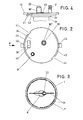
- Holes 38 and 39 are provided on the lid 16 within the annular spacing area a between the inner wall 1 'of the feeding bottle and the outer wall of the disposable bag 21.
- the volume indicator 9 ' is assigned to the hole 38.
- the hole 39 shown offset in FIG. 1, however, serves as an air inlet.
- the hole 39 is closed by a valve tab 40 attached to the outside of the cover. It is an adhesive strip. After the same has been removed, the outside air flows into the inner chamber K, for example in order to eliminate the residual negative pressure or to reduce the maximum vacuum. This is important for the individual adaptation to different surgical cases.
- the suction bottle cover 16 is assigned by means of a plug-turn connection. For this purpose, it has insertion niches 41 at diametrically opposite regions. The latter allow the free plug-in passage in the region of diametrically opposite projections 42 of the edge of the suction bottle, the front edge 4 of which bears the flexible sealing ring 5 above.
- the edge region lying here in a sealing manner is turned out with respect to the central lid surface, which corresponds dimensionally to the inner cross section of the cylindrical bottle, so that this projecting zone secures the lid 16 against transverse displacement.
- the latter begin at about half the height of the insertion niches and end on the top of the cover, possibly with the formation of an end stop shoulder.
- the clamping starts after about a turning range of 25 °, so that a complete overflow of the clamping surfaces is practically impossible.
Landscapes
- Health & Medical Sciences (AREA)
- Heart & Thoracic Surgery (AREA)
- Vascular Medicine (AREA)
- Engineering & Computer Science (AREA)
- Anesthesiology (AREA)
- Biomedical Technology (AREA)
- Hematology (AREA)
- Life Sciences & Earth Sciences (AREA)
- Animal Behavior & Ethology (AREA)
- General Health & Medical Sciences (AREA)
- Public Health (AREA)
- Veterinary Medicine (AREA)
- External Artificial Organs (AREA)
Applications Claiming Priority (2)
| Application Number | Priority Date | Filing Date | Title |
|---|---|---|---|
| DE19813150500 DE3150500A1 (de) | 1981-12-21 | 1981-12-21 | Saugflasche fuer medizinische zwecke |
| DE3150500 | 1981-12-21 |
Publications (2)
| Publication Number | Publication Date |
|---|---|
| EP0082510A1 EP0082510A1 (de) | 1983-06-29 |
| EP0082510B1 true EP0082510B1 (de) | 1988-03-02 |
Family
ID=6149256
Family Applications (1)
| Application Number | Title | Priority Date | Filing Date |
|---|---|---|---|
| EP19820111761 Expired EP0082510B1 (de) | 1981-12-21 | 1982-12-17 | Saugflasche für medizinische Zwecke |
Country Status (5)
| Country | Link |
|---|---|
| US (1) | US4522623A (da) |
| EP (1) | EP0082510B1 (da) |
| JP (1) | JPS58109061A (da) |
| DE (2) | DE3150500A1 (da) |
| DK (1) | DK162815C (da) |
Families Citing this family (44)
| Publication number | Priority date | Publication date | Assignee | Title |
|---|---|---|---|---|
| DE3410163A1 (de) * | 1984-03-20 | 1985-09-26 | Alfred 8500 Nürnberg Pongratz | Vakuumbehaelter zum absaugen von sekreten aus wundhoehlen |
| JPS62500081A (ja) * | 1984-08-29 | 1987-01-16 | シユテリメ−ト ゲゼルシヤフト フユ−ル メデイツイ−ニツシエン ベダルフ ミツト ベシユレンクテル ハフツング | レドン↓−創傷排膿法用低圧瓶 |
| US4744785A (en) * | 1984-10-02 | 1988-05-17 | C. R. Bard, Inc. | Autotransfusion system |
| EP0256060A1 (en) * | 1986-01-31 | 1988-02-24 | OSMOND, Roger L. W. | Suction system for wound and gastro-intestinal drainage |
| US5133703A (en) * | 1986-02-18 | 1992-07-28 | Boehringer Laboratories | Process and apparatus for collecting blood of a patient for autotransfusion |
| US4781707A (en) * | 1986-02-18 | 1988-11-01 | Boehringer Laboratories | Process and apparatus for collecting blood from a body cavity for autotransfusion |
| US4775366A (en) * | 1986-09-02 | 1988-10-04 | Richard Rosenblatt | Aspirator for collection of bodily fluid |
| WO1988010124A1 (en) * | 1987-06-26 | 1988-12-29 | Nova Medical Pty. Limited | Suction operation collection bag |
| US5201703A (en) * | 1987-09-29 | 1993-04-13 | Conmed Corporation | Apparatus for collecting blood from a chest drainage unit and reinfusion of the blood |
| US5078677A (en) * | 1987-09-29 | 1992-01-07 | Conmed Corporation | Apparatus for collecting blood from a chest drainage unit and reinfusion of the blood |
| US4870975A (en) * | 1988-07-05 | 1989-10-03 | Scott Cronk | Suction canister assembly for the collection of body fluids and tissue specimens |
| JPH04219939A (ja) * | 1990-12-20 | 1992-08-11 | Matsushita Electric Ind Co Ltd | 半田滴下装置 |
| JPH0620528Y2 (ja) * | 1990-12-21 | 1994-06-01 | 技術研究組合医療福祉機器研究所 | 医療用廃液処理具 |
| US5223228A (en) * | 1991-02-25 | 1993-06-29 | Baxter International Inc. | Tray for autotransfusion module |
| US5382244A (en) * | 1991-02-25 | 1995-01-17 | Baxter International Inc. | Stand alone control module |
| US5149325A (en) * | 1991-02-25 | 1992-09-22 | Baxter International Inc. | Vacuum system for auto transfusion device |
| JPH05247605A (ja) * | 1992-03-03 | 1993-09-24 | Fuji Oozx Kk | 内燃機関のバルブシート及びその製造方法 |
| US5275585A (en) * | 1992-06-03 | 1994-01-04 | Zimmer Patient Care | Autotransfusion system with portable detachable vacuum source |
| US5470324A (en) * | 1993-07-01 | 1995-11-28 | Baxter International Inc. | Non-refluxing suction canister system and components therefor |
| DE4332070A1 (de) * | 1993-09-21 | 1995-03-23 | Hippokratec Ges Fuer Medizinst | Apparat zur Perfusion von (Spül-) Flüssigkeit in Körperhöhlen |
| DE9404048U1 (de) * | 1994-03-10 | 1994-08-18 | Infus Medical International Ve | Vorrichtung für den Vakuum-Wundverschluß und/oder zum Absaugen von Sekret o.dgl. |
| US5772607A (en) * | 1995-06-06 | 1998-06-30 | The Nemours Foundation | Body fluid collection apparatus |
| US7207966B2 (en) | 1995-11-01 | 2007-04-24 | Ethicon, Inc. | System for fluid retention management |
| US6238366B1 (en) | 1996-10-31 | 2001-05-29 | Ethicon, Inc. | System for fluid retention management |
| WO1998035718A1 (en) * | 1997-02-13 | 1998-08-20 | Tyco Group S.A.R.L. | Blood evacuating system and method of use thereof |
| US6152902A (en) * | 1997-06-03 | 2000-11-28 | Ethicon, Inc. | Method and apparatus for collecting surgical fluids |
| DE19723197C2 (de) * | 1997-06-03 | 1999-07-29 | Braun Melsungen Ag | Absaugvorrichtung für Körperflüssigkeiten |
| US6183453B1 (en) * | 1997-11-20 | 2001-02-06 | Sherwood Services, Ag | Blood evacuation container with blood spike nesting feature |
| IT1297121B1 (it) * | 1997-12-16 | 1999-08-03 | Sviluppo Materiali Spa | Dispositivo chirurgico di irrigazione e di aspirazione di una soluzione fisiologica |
| GB2333763A (en) * | 1998-01-31 | 1999-08-04 | Peter Bremner | Fluid bag for brake bleeding |
| US6305545B1 (en) | 2000-06-27 | 2001-10-23 | Advanced Micro Devices, Inc. | Moisture barrier Q pack shipping box |
| GB0113750D0 (en) * | 2001-06-06 | 2001-07-25 | Rocket Medical Plc | Autologous blood transfusion apparatus |
| US7172579B2 (en) * | 2003-09-09 | 2007-02-06 | Civco Medical Instruments Co., Inc. | System and method for irrigation and tissue evacuation and collection |
| US8512301B2 (en) * | 2005-02-08 | 2013-08-20 | Feng Ma | Canned vacuum |
| GB2434996B (en) * | 2006-02-10 | 2010-10-13 | Benjamin Crawshaw | Balloon filling machine |
| US7540855B2 (en) * | 2007-06-01 | 2009-06-02 | Peregrine Surgical, Ltd. | Disposable aspirator cassette |
| US7833206B1 (en) | 2010-02-02 | 2010-11-16 | Peregrine Surgical, Ltd. | Method and apparatus for disposable aspirator cassette |
| US20110198353A1 (en) * | 2010-02-12 | 2011-08-18 | Tsao Yu-Yao | Waste liquid guide device with quickly replaceable inner bag |
| US8529501B2 (en) * | 2010-06-04 | 2013-09-10 | Medela Holding Ag | One time use breastpump assembly |
| DE202016100155U1 (de) * | 2016-01-14 | 2017-04-20 | Pfm Medical Ag | Unterdruckbehältnis |
| US10172993B2 (en) * | 2016-04-14 | 2019-01-08 | Fresenius Medical Care Holdings, Inc. | Wave-based patient line blockage detection |
| CN106668961A (zh) * | 2016-08-01 | 2017-05-17 | 江苏怡龙医疗科技有限公司 | 一种可调整式引流袋 |
| CN108525032A (zh) * | 2018-05-14 | 2018-09-14 | 无锡市人民医院 | 一种新型吸引瓶 |
| EP3804803A1 (en) * | 2019-10-10 | 2021-04-14 | Serres Oy | A valve for a pouch for collecting a fluid flow and a use of the valve |
Family Cites Families (21)
| Publication number | Priority date | Publication date | Assignee | Title |
|---|---|---|---|---|
| US2194004A (en) * | 1934-12-14 | 1940-03-19 | Roman B Bukolt | Preserving jar cap and indicator |
| US2815621A (en) * | 1955-04-28 | 1957-12-10 | Carter Clarence Freemont | Method and apparatus for filling open mouth receptacles |
| DE1810801A1 (de) * | 1968-11-25 | 1970-06-04 | Dr Med Gerhard Metz | Saugvorrichtung mit Einmalbeuteln fuer chirurgische Wunddrainagen |
| US3680560A (en) * | 1968-11-26 | 1972-08-01 | Voys Inc Le | Vacuum drainage collecting apparatus with disposable liner |
| US3646935A (en) * | 1969-08-21 | 1972-03-07 | Medical Dev Corp | Fluid collection systems |
| NL7002440A (da) * | 1970-02-20 | 1971-08-24 | ||
| US3719197A (en) * | 1971-03-04 | 1973-03-06 | Voys Inc Le | Aseptic suction drainage system and valve therefor |
| CH531351A (de) * | 1971-05-18 | 1972-12-15 | Bbc Brown Boveri & Cie | Sekretabsauggerät |
| JPS4899988A (da) * | 1972-03-30 | 1973-12-17 | ||
| US3809085A (en) * | 1972-05-23 | 1974-05-07 | Deknatel Inc | Surgical drainage system |
| CH555183A (de) * | 1972-08-23 | 1974-10-31 | Mathys Robert | Saugdrainageapparat. |
| US3768478A (en) * | 1972-08-25 | 1973-10-30 | Vermitron Medical Prod Inc | Aspiration device for body fluids |
| US3830238A (en) * | 1972-11-07 | 1974-08-20 | Deknatel Inc | Surgical drainage system with pressure measuring device |
| US4004590A (en) * | 1974-11-15 | 1977-01-25 | Health Technology Laboratories, Inc. | Medical/surgical suction equipment |
| US4058123A (en) * | 1975-10-01 | 1977-11-15 | International Paper Company | Combined irrigator and evacuator for closed wounds |
| US4135515A (en) * | 1975-12-03 | 1979-01-23 | Health Technology Laboratories, Inc. | Medical/surgical suction equipment |
| US4289158A (en) * | 1976-09-10 | 1981-09-15 | C. R. Bard, Inc. | Suction control apparatus |
| DE2840865A1 (de) * | 1978-09-20 | 1980-03-27 | Sterimed Gmbh | Verbindungsschlauch |
| NL8000048A (nl) * | 1979-01-11 | 1980-07-15 | Howmedica | Wegruimbare wondaftapinrichting. |
| US4430084A (en) * | 1980-01-21 | 1984-02-07 | American Hospital Supply Corp. | Method for pre-use storage of a medical receptacle |
| US4346711A (en) * | 1981-01-16 | 1982-08-31 | Sherwood Medical Industries Inc. | Body fluid collection device with disposable liner |
-
1981
- 1981-12-21 DE DE19813150500 patent/DE3150500A1/de not_active Withdrawn
-
1982
- 1982-12-07 US US06/447,558 patent/US4522623A/en not_active Expired - Fee Related
- 1982-12-17 DE DE8282111761T patent/DE3278152D1/de not_active Expired
- 1982-12-17 EP EP19820111761 patent/EP0082510B1/de not_active Expired
- 1982-12-20 DK DK561282A patent/DK162815C/da not_active IP Right Cessation
- 1982-12-21 JP JP57223104A patent/JPS58109061A/ja active Pending
Also Published As
| Publication number | Publication date |
|---|---|
| DE3278152D1 (en) | 1988-04-07 |
| JPS58109061A (ja) | 1983-06-29 |
| DK162815B (da) | 1991-12-16 |
| DE3150500A1 (de) | 1983-06-30 |
| DK561282A (da) | 1983-06-22 |
| DK162815C (da) | 1992-05-18 |
| EP0082510A1 (de) | 1983-06-29 |
| US4522623A (en) | 1985-06-11 |
Similar Documents
| Publication | Publication Date | Title |
|---|---|---|
| EP0082510B1 (de) | Saugflasche für medizinische Zwecke | |
| EP0861668B1 (de) | Einrichtung zum Absaugen von Flüssigkeiten | |
| EP2145637B1 (de) | Absaugpumpeneinheit | |
| DE19723197C2 (de) | Absaugvorrichtung für Körperflüssigkeiten | |
| DE2642298A1 (de) | Trinkmundstueck fuer flaschen oder aehnliche behaelter | |
| DE10100549B4 (de) | Salzbehältersystem für Dialysegeräte | |
| DE4208656C2 (de) | Luftdicht verschließbarer Frischhaltebehälter | |
| WO1995024230A1 (de) | Vorrichtung für den vakuum-wundverschluss und/oder zum absaugen von sekret oder dgl. | |
| DE2439392A1 (de) | Vorrichtung und verfahren zum aseptischen sammeln von fluiden durch unterdruck | |
| DE2103487A1 (de) | Kleinkind-Nährflasche | |
| DE4231635C2 (de) | Behälter zur Aufbewahrung und zum Transport von fließfähigen Medien, vornehmlich von Flüssigkeiten | |
| DE3538971C2 (de) | Vorrichtung zum Aufbringen und/oder Entfernen eines Drehverschlußdeckels auf einen bzw. von einem Behälter | |
| DE3210819C2 (de) | Flüssigkeitsbehälter | |
| EP1797915B1 (de) | Hämodialyse-Salzbehälter mit Belüftung | |
| EP3175754B1 (de) | Entnahmesystem für tuchspender | |
| EP0355456A2 (de) | Blutbegasungsvorrichtung | |
| DE3500538C2 (da) | ||
| WO1998055367A1 (de) | Eimer für farbe oder klebstoff | |
| DE2629625C2 (de) | Entnahmevorrichtung für Flüssigkeitsbehälter | |
| DE2532899A1 (de) | Staubsauger | |
| DE202014103303U1 (de) | Entnahmesystem für Tuchspender | |
| DE202008005025U1 (de) | Befestigungsvorrichtung für einen Drainagebehälter | |
| DE2354106C2 (da) | ||
| DE4445623C1 (de) | Handgerät zur Absaugung von Altöl aus Kraftfahrzeugen | |
| DE1937754C3 (de) | Transportable Toilette |
Legal Events
| Date | Code | Title | Description |
|---|---|---|---|
| PUAI | Public reference made under article 153(3) epc to a published international application that has entered the european phase |
Free format text: ORIGINAL CODE: 0009012 |
|
| AK | Designated contracting states |
Designated state(s): CH DE FR GB IT LI SE |
|
| 17P | Request for examination filed |
Effective date: 19831004 |
|
| ITF | It: translation for a ep patent filed |
Owner name: STUDIO INGG. FISCHETTI & WEBER |
|
| GRAA | (expected) grant |
Free format text: ORIGINAL CODE: 0009210 |
|
| AK | Designated contracting states |
Kind code of ref document: B1 Designated state(s): CH DE FR GB IT LI SE |
|
| GBT | Gb: translation of ep patent filed (gb section 77(6)(a)/1977) | ||
| REF | Corresponds to: |
Ref document number: 3278152 Country of ref document: DE Date of ref document: 19880407 |
|
| ET | Fr: translation filed | ||
| PLBE | No opposition filed within time limit |
Free format text: ORIGINAL CODE: 0009261 |
|
| STAA | Information on the status of an ep patent application or granted ep patent |
Free format text: STATUS: NO OPPOSITION FILED WITHIN TIME LIMIT |
|
| 26N | No opposition filed | ||
| PGFP | Annual fee paid to national office [announced via postgrant information from national office to epo] |
Ref country code: SE Payment date: 19911118 Year of fee payment: 10 |
|
| PGFP | Annual fee paid to national office [announced via postgrant information from national office to epo] |
Ref country code: FR Payment date: 19911122 Year of fee payment: 10 |
|
| PGFP | Annual fee paid to national office [announced via postgrant information from national office to epo] |
Ref country code: GB Payment date: 19911209 Year of fee payment: 10 Ref country code: DE Payment date: 19911209 Year of fee payment: 10 |
|
| ITTA | It: last paid annual fee | ||
| PGFP | Annual fee paid to national office [announced via postgrant information from national office to epo] |
Ref country code: CH Payment date: 19920330 Year of fee payment: 10 |
|
| PG25 | Lapsed in a contracting state [announced via postgrant information from national office to epo] |
Ref country code: GB Effective date: 19921217 |
|
| PG25 | Lapsed in a contracting state [announced via postgrant information from national office to epo] |
Ref country code: SE Effective date: 19921218 |
|
| PG25 | Lapsed in a contracting state [announced via postgrant information from national office to epo] |
Ref country code: LI Effective date: 19921231 Ref country code: CH Effective date: 19921231 |
|
| GBPC | Gb: european patent ceased through non-payment of renewal fee |
Effective date: 19921217 |
|
| PG25 | Lapsed in a contracting state [announced via postgrant information from national office to epo] |
Ref country code: FR Effective date: 19930831 |
|
| REG | Reference to a national code |
Ref country code: CH Ref legal event code: PL |
|
| PG25 | Lapsed in a contracting state [announced via postgrant information from national office to epo] |
Ref country code: DE Effective date: 19930901 |
|
| REG | Reference to a national code |
Ref country code: FR Ref legal event code: ST |
|
| EUG | Se: european patent has lapsed |
Ref document number: 82111761.1 Effective date: 19930709 |