EP0067668B1 - Vorrichtung zum Messen der Position einer Metalloberfläche - Google Patents
Vorrichtung zum Messen der Position einer Metalloberfläche Download PDFInfo
- Publication number
- EP0067668B1 EP0067668B1 EP19820302999 EP82302999A EP0067668B1 EP 0067668 B1 EP0067668 B1 EP 0067668B1 EP 19820302999 EP19820302999 EP 19820302999 EP 82302999 A EP82302999 A EP 82302999A EP 0067668 B1 EP0067668 B1 EP 0067668B1
- Authority
- EP
- European Patent Office
- Prior art keywords
- sensor
- output
- mold
- signal
- strip
- Prior art date
- Legal status (The legal status is an assumption and is not a legal conclusion. Google has not performed a legal analysis and makes no representation as to the accuracy of the status listed.)
- Expired
Links
Images





Classifications
-
- G—PHYSICS
- G01—MEASURING; TESTING
- G01F—MEASURING VOLUME, VOLUME FLOW, MASS FLOW OR LIQUID LEVEL; METERING BY VOLUME
- G01F23/00—Indicating or measuring liquid level or level of fluent solid material, e.g. indicating in terms of volume or indicating by means of an alarm
- G01F23/0023—Indicating or measuring liquid level or level of fluent solid material, e.g. indicating in terms of volume or indicating by means of an alarm with a probe suspended by a wire or thread
-
- G—PHYSICS
- G01—MEASURING; TESTING
- G01F—MEASURING VOLUME, VOLUME FLOW, MASS FLOW OR LIQUID LEVEL; METERING BY VOLUME
- G01F23/00—Indicating or measuring liquid level or level of fluent solid material, e.g. indicating in terms of volume or indicating by means of an alarm
- G01F23/22—Indicating or measuring liquid level or level of fluent solid material, e.g. indicating in terms of volume or indicating by means of an alarm by measuring physical variables, other than linear dimensions, pressure or weight, dependent on the level to be measured, e.g. by difference of heat transfer of steam or water
- G01F23/26—Indicating or measuring liquid level or level of fluent solid material, e.g. indicating in terms of volume or indicating by means of an alarm by measuring physical variables, other than linear dimensions, pressure or weight, dependent on the level to be measured, e.g. by difference of heat transfer of steam or water by measuring variations of capacity or inductance of capacitors or inductors arising from the presence of liquid or fluent solid material in the electric or electromagnetic fields
Definitions
- the present invention relates to an apparatus for measuring metal surface position, and more particularly to an apparatus for non-contact measuring a surface position of metallic mass such as molten steel, shielded and unaccessible metal or moving metal which is difficult to be directly measured.
- an automatic tracing or follow measuring apparatus In detecting the level of molten steel in a mold of a continuous steel casting, an automatic tracing or follow measuring apparatus has been proposed, in which a detection coil which is movable by a servo motor is arranged at a predetermined distance from a molten metal surface, change of distance between the melt surface and the detection coil due to movement of the melt surface is detected from a change in inductance of the detection coil, the servo motor is driven by the detection signal so that the detection coil is moved to maintain the predetermined distance from the melt surface and the melt surface is measured based on the distance in movement of the detection coil driven by the servo motor.
- Such a measuring apparatus is disclosed in, for example, Japanese Patent Publication No. 54-42846, and Japanese Patent Application No. 53-152949.
- the measuring from change in inductance is valid only when the inductance varies linearly to the change of distance. Since some noises due to influence of the mold or a peripheral equipment are usually included, the distance between the molten steel surface and the detector is not always in linear relationship with the inductance of the detector.
- US-A-4186792 discloses a molten metal level monitoring and controlling apparatus for a continuous casting machine.
- Detecting means in the form of an eddy-current type distance measuring device is used for measuring molten metal level and comprises a feedback amplifier circuit including a detecting coil disposed just above the surface of the molten metal, an AC constant- voltage reference oscillator for providing AC voltage, a differential amplifier, a positive feedback circuit and an amplitude detection circuit.
- a supporting mechanism for positioning the detecting means just above the surface of the metal is provided with a vertical shifting mechanism including a servomotor for vertically moving the detecting means and controlled to maintain a preset distance between the detecting means and the surface of the molten metal.
- US-A-4 074 201 discloses a signal analyzer with noise estimation and signal to noise readout in which a baseband signal including noise is compared at timed intervals with a reference signal and an estimated noise signal from a noise generator. Indications of whether the estimated noise signal is higher or lower than the noise level present are applied to a digital accumulator in the estimated noise signal generator. Certain of the most significant bits in the accumulator are employed to generate an analog estimated noise signal.
- an apparatus for measuring a change along a predetermined direction of a surface position of a metallic mass comprising:
- Fig. 1 showing a circuit configuration of one embodiment of the present invention, which is particularly designed to measure a melt surface position or level in a mold of a continuous casting for making steel slabs
- numeral 1 denotes a detector which uses a magnetic sensor of flux-balanced type
- numeral 2 denotes a potentiometer
- numeral 3 denotes a distance detector
- numeral 4 denotes a reference level setter
- numeral 5 denotes a comparator
- numeral 6 denotes a servo circuit
- numeral 7 denotes a servo motor
- numeral 8 denotes an amplifier
- numeral 9 denotes a level indicator
- numeral 14 denotes a strip for transmitting the driving power of the servo motor to the sensor 1
- numeral 18 denotes a free wheel
- numeral 15 denotes a strip take-up drum
- numeral 16 denotes a mold
- numeral 17 denotes molten steel.
- the molten steel is supplied into the mold 16 from a tundish (not shown) disposed above the mold 16, while the molten metal is discharged as cooled in a form of solidified slab of a rectangular cross-section from the bottom of the mold 16 so that the slab is continuously casted.
- a mold spacing d between side walls of the mold 16 determines a slab thickness and it varies with a dimension of the slab to be casted.
- the sensor 1 has a detection coil as described later, and when a distance 25 between the sensor 1 and the molten steel level changes, the impedance of the detection coil changes and the sensor produces an electrical signal representative of the change of the distance 25.
- the electrical signal is detected and amplified by the distance detector 3, an output signal of which is applied to the comparator 5.
- the output signal of the distance detector 3 is compared with a predetermined reference signal indicative of a predetermined value of the distance between the sensor and the molten metal surface and an error signal therebetween is supplied to the servo motor 7 through the motor driver 6 to drive the servo motor 7, which is turn drives the sensor 1 through the strip 14 wound on the drum 15 to maintain the distance 25 at the predetermined length.
- the displacement of the level of the molten steel 17 corresponds to the distance of movement of the strip 14 by the servo motor 7, and the distance of movement is converted by the potentiometer 2 to an electrical signal, which indicated by the indicator 9 through the amplifier 8 and/or used to control other associated devices (not shown).
- the output of the sensor 1 significantly changes by noises due to such as influences by a change of size of the mold 16 depending on the dimension of the slab to be casted or a change of the position of the sensor 1 relative to the mold 16.
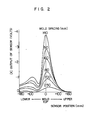
- Fig. 2 shown relationships between outputs of the sensor 1 and the positions of the sensor 1 relative to the mold 16, measured for various mold spacings d. An ordinate represents a D.C.
- the output (in volts) of the sensor 1 and an abscissa represents a vertical position of the sensor 1 relative to the mold.
- the sensor position corresponding to the top of the mold 16 is represented by "0", and the sensor 1 is descended from a position at 155 mm higher than the top of the mold to a lower limit position at -180 mm therefrom.
- the output is more or less influenced by the mold.
- the influence is largest when the sensor is positioned at "0" mm or near, i.e. near to the top of the mold and the influence is observed even when the sensor is positioned around -80 mm- -100 mm therefrom.
- the metal surface position detector using a magnetic sensor is affected by not only the metal surface to be measured but also the periphery into which the magnetic fluxes thereof are introduced.
- the same is true for a sensor which uses an electro-magnetic coil.
- the sensor is influenced by not only the molten steel surface but also the mold surface and the periphery.
- an error from an ideal value amounts to a value corresponding to 18 mm of the distance between the metal surface and the sensor for the mold spacing of 200 mm, although it depends on the size of the sensor.
- the error amounts to a value corresponding to 30 mm of the distance which may be larger than the actual distance to the molten steel level.
- it cannot follow the molten steel level in the mold and senses the mold as if it were the molten steel level, thereby preventing the sensor from following the molten steel level.
- the noises or the influences imparted to the measurement due to the factors other than the metal surface-to-sensor distance, as shown in Fig. 2 are stored in a memory, and they are read out of the memory in the measurement operation and applied as correction factors to a measurement control system including the sensor 1 and the motor driver 6. Simply speaking, the detected value less the noises is used as the sensor-to-metal surface distance signal.
- Fig. 1 embodies the above principle of the present invention.
- Numeral 22 denotes a static random access memory (RAM) which is used as the memory described above.
- Read/write addresses of the RAM 22 are specified by output data of an A/D converter 19.
- an output of the amplifier 8 that is, a sensor level signal is supplied to the A/D converter 19 through a switch 27h while keeping the mold 16 stationary and moving the sensor 1 from the lower limit position to the upper limit position by the servo motor 7, and when the molten steel level is measured, a sum output of an adder 26 is supplied to the A/D converter 19.
- an up-and-down mechanical vibration of constant-cycle and constant- amplitude is applied to the mold 16 by a vibrator 29 so that the relative position of the sensor 1 to the mold 16 periodically changes.
- a vibration displacement from a bottom dead point of the vibration is sensed by a displacement sensor 30 and it is applied to the adder 26 where it is added to the position signal of the sensor 1, i.e. the output of the amplifier 8, and the relative position of the sensor 1 to the mold 16 is applied to the A/D converter 19.
- An A/D converter 21 supplies the write data to the RAM 22. When the environmental noise is written into the RAM 22, the distance signal from the detector 3 is applied to the A/D converter 21 through a switch 27e.
- the output data of the A/D converter 21 is stored in the RAM 22 at the address specified by the output data of the A/D converter 19, and when the switch 27g is open, the stored data (environmental noise) of the RAM 22 at the address specified by the output data of the A/D converter 19 is read out to a D/A converter 24.
- the D/A converter 24 converts the.readout data to an analog signal, which is then applied to the adder 12.
- the adder 12 adds a reference value from the setter 4 to the readout value and supplies a resulting sum to the comparator 5.
- the reference value represents a predetermined distance which is to be maintained between the sensor 1 and the metal surface under measurement.
- a switch 27d is inserted between the comparator 5 and the motor driver 6.
- the switch 27d In a write operation in which the environmental noise (hereinafter referred to as a noise data) is set to the RAM 22, the switch 27d is in a position to connect the motor driver 6 to a motor forward/ backward switch 27b.
- Numeral 27a denotes a noise data write switch
- numeral 27c denotes a write switch which is closed in the write operation
- numeral 27f denotes a code change detector which produces a write pulse (plus H) of a predetermined duration when the output code from the A/D converter 19 changes.
- the code change detector 27f latches the output code from the A/D converter 19 and compares the latched code with the next output code from the A/D converter 19, and if they are not equal, it updates the latched code by the newly applied code and produces the write pulse.
- the latched code is initially set to "0" at the start of the operation.
- the noise data write operation is now explained in a case where the write operation is carried out when the molten metal is absent.
- An operator first closes the switch 27a.
- the switch 27b is connected to the motor driver 6 through the switch 27d, the switch 27e is closed and the output line of the amplifier 8 is connected to the A/D converter 19 through the switch 27h.
- the mold 16 is located at the bottom dead point in vibration of the mold by the vibrator 29 and throws the switch 27b to a side of +Vcc or -Vcc so that the motor 7 is driven forwardly or backwardly to move the sensor 1 to the bottom point or the top point of the vertical movement range.
- the motor 7 is driven forwardly (by applying a voltage of +Vcc) to position the sensor 1 at the bottom point. Then, the operator closes the switch 27c and throws the switch 27b to the side of -Vcc. As a result, the motor 7 is driven backwardly at a constant speed so that the sensor 1 is moved up at a constant speed. As the sensor 1 goes up, the output voltage (sensor level signal) of the amplifier 8 linearly changes. Consequently, the digital output value of the A/D converter 19 changes by "1" each time when the analog output value of the amplifier 8 changes by the amount corresponding to the minimum unit of the digital output of the A/D converter 19.
- the detector 27f When the digital output of the A/D converter 19 changes by "1", the detector 27f produces a pulse, which causes the switch 27g to be closed through the switch 27c to instruct the "write” operation to the RAM 22.
- the switch 27g each time when the sensor 1 goes up by the distance corresponding to the minimum unit of the A/D converter 19, that is, each time when the output code of the A/D converter 19 changes by "1", the current output or the current noise data of the detector 3 is written into the RAM 22 at the address specified by the output code.
- the operator When the sensor 1 reaches the top point, the operator returns the switch 27b to a neutral position to stop the motor 7 and opens the switch 27c.
- the operator opens the switch 27a.
- the comparator 5 is connected to the motor driver 6 through the switch 27d
- the switch 27e is opened
- the adder 26 is connected to the A/D converter 19 through the switch 27h. Consequently, the adder 26 supplies to the A/D converter 19 the relative position signal, which is derived by correcting the position of the sensor 1 (output of the amplifier 8) by the displacement due to the vibration of the mold 16.
- the access address of the RAM 22 is specified by the relative positon data of the sensor 1 to the vibrating mold 16 and the noise data stored at the specified address is read out and converted to an analog data by the D/A converter 24, and the analog data is supplied to the adder 12 where it is added to the value representing the predetermined reference distance 25, and a resulting sum is applied to the comparator 5.
- the comparator 5 compares the output of the distance detector 3 with the output of the adder 12 and produces a signal (plus or minus) representing a difference therebetween, that is, a difference between the detector output less the environmental noise, which should represent the correct metal surface distance, and the reference value. This signal is supplied to the motor driver 6 through the switch 27d.
- the follow-surface control to keep the distance between the metal surface and the sensor 1 at the reference distance can be attained.
- the distance between the metal surface and the sen - sor 1 could significantly deviate from the reference distance because of the inclusion of the noise in the detector data and hence the indication by the indicator 9 includes a large error.
- the sensor 1 since the reference value is corrected by the adder 12 so that the environmental noise is cancelled at the comparator 5, the sensor 1 exactly follows the movement of the metal surface and the distance between the metal surface and the sensor 1 is kept at the reference value and therefore, the indication of the indicator 9 is exact.
- the write operation described above is carried out under a conditon that no molten steel exists in the mold 16.
- a non-magnetic metal plate of about 10 mm thickness such as lead plate or aluminum plate to the sensor 1 at a position below the sensor 1 spaced by a distance equal to the reference distance between the sensor 1 and the metal surface to be measured and to move the sensor 1 together with the non-magnetic metal plate up and down in the mold 1 and store the output values of the sensor 1 at various levels of the sensor 1.
- the output of the sensor includes the value representing the distance which would exist between the sensor 1 and the molten metal surface if the sensor 1 exactly follows the molten metal surface with the reference distance and the enviromental noises. Therefore, when the write operation is carried out in this manner, it is not required in the measurement operation to add the reference distance to the output of the D/A converter 24 in the adder 12 and thus, the reference signal setter 4 and the adder 12 can be omitted.
- Figs. 3 and 4 show relations between the level of the sensor 1 or the level output and the level of the lead plate surface (corresponding to the molten metal level) with mold spacings of 140 mm and 160 mm.
- the noise by the mold, an ideal measurement value, a comparative value by the prior art and a corrected measurement value by the present invention are plotted.
- the ordinate represents the level (mm) of the sensor 1 or the level output and the abscissa represents the lead plate surface level (mm) (corresponding to the molten metal level).
- the reference distance between the sensor 1 and the lead plate surface is set to 90 mm.
- the sensor 1 detects the lead plate surface from a position distant by 90 mm therefrom.
- the noise by the mold 16 is shown by a DC output of the sensor 1.
- the sensor 1 used in the measurement is different from that used in the measurement of Fig. 2 and hence the output values are different from each other.
- the senor 1 cannot descend below +48 mm level from the top end of the mold when the mold spacing is 140 mm and hence the sensor 1 does not follow the level change of the lead plate surface but senses as if the lead plate were at the level of +48 mm.
- the sensor 1 cannot descend below a level of +20 mm and also it involves a larger error from the ideal value so that the sensor 1 cannot be applicable to the level measurement.
- an error from the ideal value is 5 mm at maximum, if not zero, and the present invention significantly facilitates the measurement and improves the accuracy in measurement. While not shown in Figs. 3 and 4, when the noise by the mold 16 was compensated by using the noise data measured as moving the metal plate together with the sensor 1 as described above, an error from the ideal value was less than 1 mm.
- the output signal from the static RAM 11 and the output signal from the reference level setter 4 are added together by the adder 12.
- the output signal from the detector 3 connected to the sensor 1 and the output signal from the reference level setter 4 may be applied to the adder 12 and a resulting sum may be stored in the RAM 22.
- a switch 28 is closed if the mold 16 is empty and opened if the non-magnetic metal plate (e.g., lead plate or aluminum plate) is attached below the sensor 1.
- the adder 12 is replaced by a subtractor 12a so that the noise data stored in the RAM 22 is subtracted from the output signal of the detector 3 connected to the sensor 1, and a'resulting difference is compared with the output signal from the reference level setter 4.
- the write operation may be carried out by using a non-magnetic metal plate fixed to the sensor 1 with a predetermined distance therebetween. In that case, the output of the subtractor 12a is directly applied to the motor driver 6.
- Fig. 7 shows another embodiment, in which a microcomputer system 31 writes the noise data and effects the follow-surface control of the sensor 1 in the measurement operation by actuation of a key switch 32.
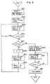
- a central processing unit (CPU) 31 a starts to execute a memory routine shown in a flow chart of Fig. 8 under control of a program stored in a ROM 31c.
- the system 31 is initialized so that the data N which specifies the write address of the RAM 22 is set to "0" and the motor 7 is driven to position the sensor 1 at the top position.
- the motor driver 6 is instructed to descend the sensor 1.
- an A/D converter 31 d is instructed to A/D-convert a signal on its input channel 3 and produce a resulting converted data D, and if the converted data is different from the previously stored write address data (step 804), the current converted data D is used to update the write address N of the RAM 22 (step 806). Then, the A/D converter 31 d is instructed to A/D-convert a signal on its input channel 2 and produce a converted data P (step 807), and the data P is written into the RAM 22 at the address N (step 808).
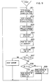
- the system 31 executes a measurement routine shown in Fig. 9 under control of the program stored in the ROM 31c to measure the metal surface level.
- the above memory routine and the measurement routine are executed at a timing determined by clock signals from a clock signal generator (not shown) contained in the system 31.
- One cycle of each routine is selected to be shorter than a time period required for the sensor 1 to be moved by a distance corresponding to the minimum unit of the digital value which is derived from the A/D conversion of the signal on the input channel 3 of the A/D converter 31 d.
- the strip 14 is connected at its one end to the rotating drum to be wound on or rewound from the drum for vertically moving the sensor by rotating the drum forwardly or reversely.
- the drum is replaced by a mechanism for converting the rotational movement into a linear movement. This mechanism is useful to readily and accurately measure the moving distance of the sensor or the strip.
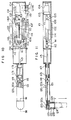
- a base plate 102 for fixing the support arm 101 to a rotary support (not shown) mounted near the mold to position the support arm 101 to a sensing position on the opening of the mold and an evacuated position which is off the opening of the mold.
- a servo motor 104 (corresponding to the servo motor 7 shown in Fig. 1) having a reducing gear 104 coupled thereto is mounted in the support arm 101, and one end of a lead screw 107 of a reciprocating mechanism 106 is coupled to an output shaft of the reducing gear 103 through a coupling 105. The other end of the lead screw 107 is pivoted to a frame 108.
- the lead screw 107 is threadedly engaged with a nut 109 which is fixed to an end plate secured to ends of guide bars 110 1 and 110 2 .
- the guide bars l10 1 and 110 2 are slidably guided by the frame 108 along an axis of the lead screw 107, and one end of a pipe 113 is coupled to an end plate 111 secured to the other ends of the guide bars 110 1 and 110 2 through a dram guide member 112.
- a slider arm of a linear potentiometer 114 is coupled to the end plate 111.
- a switch actuation cam 115 is coupled to the nut 109 and it closes a limit switch 116R when the nut 109 reaches the rightmost position and closes a limit switch 116L when the nut 109 reaches the leftmost position.
- the pipe 113 is supported by a pair of bearings 117, and 117 2 secured to the support arm 101 and a draw guide member 118 is secured to a left end of the support arm 101.
- Ends of a flexible air pipe 119, a pair of elongated strips or belt-shaped plates 120 1 and 120 2 each having an arc-shaped cross section and an electrical cable 121 are coupled to the draw guide member 118.
- a heat resistive, non-magnetic tubular ceramic end member 122 and a belt plate guide 123 are secured to the left end of the support arm 101.
- An upper side wall of the end member 122 has an opening through which the pipe 119, the belt plates 120, and 120 2 and the cable 121 extend.
- the belt plate guide 123 has curved guide passages of a predetermined radius of curvature through which the pipe 119, the strips 120, and 120 2 and the cable 121 extend separately.
- the strips 120, and 120 2 are corresponding to the strip 14 in Fig. 1 and made of flexible and linerealy restitutive material.
- the pipe 119, the strips 120, and 120 2 and the cable 121 extending from those guide passages lead to a support plate 125 secured to a heat resistive, non-magnetic ceramic tube 124.
- the pipe 119 and the cable 121 extend through the support plate 125 and extend into a space within an electrical coil support tube 126 in the ceramic tube 124, and the strips 120 1 and 120 2 are secured to the support plates 125.
- Three electrical coils 127 1 , 127 2 and 127 3 are wound on the support tube 126 and lead wires of the electrical cable 121 are connected to those coils.
- the pipe 119 opens into the space within the support tube 126 so that pressurized air from the pipe 119 is injected into the support tube 126.
- An air gap is formed between an outer surface of the support tube 126 and an inner surface of the ceramic tube 124.
- the injected air passes through the air gap, an evacuation port of the support plate 125 and an evacuation port of the ceramic end member 122 and flows into the support arm 101.
- a bottom opening edge of a tubular (bag-like) heat resistive glass wool cloth 129 Secured to a bottom opening of the end member 122 is a bottom opening edge of a tubular (bag-like) heat resistive glass wool cloth 129, and a top opening edge of the cloth 129 is secured to a side periphery of the support plate 125 by a heat resistive ring 130 (Fig. 12).
- a heat resistive ring 130 Fig. 12
- Fig. 13 shows a top surface of the support plate 125.
- Numeral 131 denotes an aperture through which the air pipe 119 extends
- numeral 132 denotes an aperture through which the electrical cable 121 extends
- numerals 133 denote air evacuation ports.
- the air pipe 119 communicates with the inside of the pipe 113 through the aperture of the draw guide member 118, the pipe 113 communicates with a flexible air pipe 134 through the aperture of the draw guide member 118, and the air pipe 134 is connected to a pipe connector 135 at a right end of the support arm 101.
- pressured cool air is supplied into the pipe connector 135.
- the electrical cable 121 passes through the guide member 118, the pipe 113 and the guide member 112 and is connected to the electrical lead connected to the connector 136 at the right end of the support arm 101.
- the electrical coils 127 1 ⁇ 127 3 are surrounded by the ceramic tube 124 having a closed bottom in the illustrated embodiment, they may be surrounded by a heat resistive cloth like the heat resistive glass wool cloth 29.
- the tube 24 may be opened at the bottom and the tube may be surrounded by the bag-like heat resistive glass wool cloth 29.
- two belt plates are shown in the illustrated embodiment, a single belt plate may be used when the lifting head 124, 25, 26 is of light weight and/or the strip is of wide width. Usually, two or more strips are used to attain a high stability of the lifting head. Accordingly, it is desirable to use two strips as shown in the illustrated embodiment or more than two strips.
- the illustrated sensor 1 has two exciting electrical coils 127, and 127 2 and a detection coil 127 3 .
- the exciting coils 127, and 127 2 are energized even when the metal to be sensed is absent so that magnetic fluxes generated by the exciting coils 127, and 127 2 are cancelled at the intermediate detection coil 127 3 . Accordingly, linkage flux to the intermediate detection coil 127 3 is zero and an output thereof is also zero.
- impedances of the coils 127, and 127 2 change and a balance of the magnetic fluxes is lost so that linkage fluxes are produced in the detection coil 127 3 and the coil 127 3 produces an output.
- the magnitude thereof depends on a degree of unbalance, that is, a distance between the metal and the coils.
- an additional pair of third exciting coils 127 4 , and 127 42 are wound and they are connected to the first and second exciting coils 127, . and 127 2 in a manner shown in Fig. 15, in which VRa denotes a potentiometer for adjusting a current balance.
- the coils 127, and 127 2 are wound in such directions that the magnetic fluxes generated thereby are of opposite polarites to each other, and the coils 127 4 , and 127 42 are wound in such directions that the magnetic fluxes generated thereby are of opposited polarities to each other. Since the coils 127, and 127 2 are connected in series and they have equal number of turns, the magnetic fluxes generated by the coils 127, and 127 2 are cancelled out at the position of the coil 127 3 but the magnetic fluxes at the position of the coil 127 3 is not completely zero because of the deformation of the windings of the coils 127, and 127 2 and the displacement of the coils 127, and 127 2 to the coil 127 3 .
- the currents to the third coils 127 41 and 127 42 are differentially adjusted by the potentiometer VRa to bring the magnetic fluxes at the position of the coil 127 3 to be substantially zero.
- the currents in the first and second coils 127, and 127 2 do not substantially change by the adjustment of the potentiometer VRa because when the current to the coil 127 4 , (or 127 42 ) is increased by the potentiometer VRa, the current to the coil 127 42 (or 127 4 ,) is reduced correspondingly, and the sum of the currents to the coils 127 4 , and 127 42 is supplied to the first and second coils 127, and 127 2 . In this manner, by adjusting the potentiometer VRa, a balanced magnetic field is established at the position of the coil 127 3 .
- the third coils 127 4 , and 127 42 are connected in parallel, when there is a temperature difference therebetween, the resistances thereof change and the current level changes, and hence the balanced magnetic field may be disturbed.
- the coils 127 41 and 127 42 are arranged closely to each other so that the temperature difference is small, and the number of turns of the coils 127 4 , and 127 42 is much smaller than the number of turns of the coils 127, and 127 2 . Accordingly, the third coils 127 4 , and 127 42 do not significantly disturb the balanced magnetic field.
Landscapes
- Physics & Mathematics (AREA)
- Fluid Mechanics (AREA)
- General Physics & Mathematics (AREA)
- Engineering & Computer Science (AREA)
- Electromagnetism (AREA)
- Power Engineering (AREA)
- Thermal Sciences (AREA)
- Continuous Casting (AREA)
Claims (6)
Applications Claiming Priority (6)
| Application Number | Priority Date | Filing Date | Title |
|---|---|---|---|
| JP89919/81 | 1981-06-11 | ||
| JP8991981A JPS57204401A (en) | 1981-06-11 | 1981-06-11 | Detecting end supporting and driving device of metallic surface detecting and profiling device |
| JP181492/81 | 1981-11-12 | ||
| JP18149281A JPS5883222A (ja) | 1981-11-12 | 1981-11-12 | 金属位置検出装置 |
| JP57045315A JPS58161828A (ja) | 1982-03-22 | 1982-03-22 | 金属位置検出方法 |
| JP45315/82 | 1982-03-22 |
Publications (3)
| Publication Number | Publication Date |
|---|---|
| EP0067668A2 EP0067668A2 (de) | 1982-12-22 |
| EP0067668A3 EP0067668A3 (en) | 1984-06-20 |
| EP0067668B1 true EP0067668B1 (de) | 1987-11-11 |
Family
ID=27292182
Family Applications (1)
| Application Number | Title | Priority Date | Filing Date |
|---|---|---|---|
| EP19820302999 Expired EP0067668B1 (de) | 1981-06-11 | 1982-06-10 | Vorrichtung zum Messen der Position einer Metalloberfläche |
Country Status (3)
| Country | Link |
|---|---|
| EP (1) | EP0067668B1 (de) |
| AU (1) | AU529551B2 (de) |
| DE (1) | DE3277636D1 (de) |
Families Citing this family (5)
| Publication number | Priority date | Publication date | Assignee | Title |
|---|---|---|---|---|
| DE3323748A1 (de) * | 1983-07-01 | 1985-01-03 | Norddeutsche Affinerie AG, 2000 Hamburg | Verfahren zur messung und regelung des fuellstandes von in einem behaelter befindlichen stoffen |
| DE3323749A1 (de) * | 1983-07-01 | 1985-01-03 | Norddeutsche Affinerie AG, 2000 Hamburg | Verfahren zur regelung der badspiegelhoehe einer metallschmelze |
| IT1199159B (it) * | 1984-07-13 | 1988-12-30 | Centro Speriment Metallurg | Sonda per il controllo dei difetti superficiali di corpi metallici ad alta temperatura |
| FR2736433B1 (fr) * | 1995-07-04 | 1998-01-30 | Carbonnel Henri | Perfectionnement aux dispositifs de mesure du niveau des metaux liquides en fonderie |
| AU2429300A (en) * | 1998-12-23 | 2000-07-31 | Sms Demag Aktiengesellschaft | Method for detecting and controlling the level of liquid metal in an ingot mold |
Family Cites Families (5)
| Publication number | Priority date | Publication date | Assignee | Title |
|---|---|---|---|---|
| FR2108809A1 (en) * | 1970-10-07 | 1972-05-26 | Commissariat Energie Atomique | Level meter - for liquid metals eg sodium at high temp |
| US4074201A (en) * | 1976-07-26 | 1978-02-14 | Gte Sylvania Incorporated | Signal analyzer with noise estimation and signal to noise readout |
| JPS5376926A (en) * | 1976-12-21 | 1978-07-07 | Nippon Kokan Kk | Molten metal level monitor controller of continuous casting machine that use eddy flow system range finder for measurement of molten metal level |
| DE2717530B2 (de) * | 1977-04-18 | 1980-01-03 | Biotronik Mess- Und Therapiegeraete Gmbh & Co Ingenieurbuero Berlin, 1000 Berlin | Verfahren zur Störbefreiung von Signalen |
| JPS54153663A (en) * | 1978-05-24 | 1979-12-04 | Nippon Kokan Kk | Method of removing nozzle for measured signal of molten material level in mold for continuous casting |
-
1982
- 1982-06-10 EP EP19820302999 patent/EP0067668B1/de not_active Expired
- 1982-06-10 AU AU84784/82A patent/AU529551B2/en not_active Ceased
- 1982-06-10 DE DE8282302999T patent/DE3277636D1/de not_active Expired
Also Published As
| Publication number | Publication date |
|---|---|
| EP0067668A2 (de) | 1982-12-22 |
| EP0067668A3 (en) | 1984-06-20 |
| DE3277636D1 (en) | 1987-12-17 |
| AU529551B2 (en) | 1983-06-09 |
| AU8478482A (en) | 1982-12-16 |
Similar Documents
| Publication | Publication Date | Title |
|---|---|---|
| US6209217B1 (en) | Surface-following type measuring machine | |
| US5001356A (en) | Sheet thickness measuring apparatus | |
| US5315873A (en) | Liquid level detection apparatus and method thereof | |
| JPH04218817A (ja) | 物体移動制御装置 | |
| JPH04232675A (ja) | 所定の磁気記憶媒体上のトラックへ所定の書き込み/読み出しヘッドを位置定めするための方法 | |
| EP0067668B1 (de) | Vorrichtung zum Messen der Position einer Metalloberfläche | |
| JPH0114523B2 (de) | ||
| WO1985004707A1 (fr) | Machine mesurant la rugosite d'une surface | |
| JPH054006B2 (de) | ||
| EP0506005B1 (de) | Vorrichtung zur Messung der Abmessung eines eines Körpers | |
| EP0594961A1 (de) | Schätzung der Metalltemperatur über die Abnutzung des Tauchrohres auf Grund des Eintauchens in Metallschmelze | |
| KR830002811B1 (ko) | 스트랜드(Strand)안내부의 계측방법 | |
| US4442389A (en) | Apparatus for measuring a metal surface position | |
| JPH10284532A (ja) | ワイヤボンディング装置及びそのボンディング荷重補正方法 | |
| JPH0671642B2 (ja) | 溶融金属浴の表面レベルの制御方法 | |
| JP2005098863A (ja) | 固体熱膨張率測定装置 | |
| JPH0540056A (ja) | 連続鋳造鋳型の渦流式湯面レベル計の自動校正方法 | |
| JP2714149B2 (ja) | デイスク装置 | |
| JP3221990B2 (ja) | モールドレベル測定装置 | |
| JPH04348230A (ja) | レベル測定機能付き浸漬型高温溶融金属測温装置およびレベル測定機能付きサブランスプローブ | |
| US6119918A (en) | Solder head control mechanism | |
| JPH04361145A (ja) | 熱分析装置 | |
| SU1276435A1 (ru) | Способ регулировани соосности кристаллизатора и поддерживающей секции зоны вторичного охлаждени и устройство дл его осуществлени | |
| JPS58126045A (ja) | 工作機械の位置決め補正方法および装置 | |
| JPH02256481A (ja) | ロボットとワークとの相互距離制御方法およびそのための較正データ作成装置 |
Legal Events
| Date | Code | Title | Description |
|---|---|---|---|
| PUAI | Public reference made under article 153(3) epc to a published international application that has entered the european phase |
Free format text: ORIGINAL CODE: 0009012 |
|
| AK | Designated contracting states |
Designated state(s): DE FR GB IT NL |
|
| PUAL | Search report despatched |
Free format text: ORIGINAL CODE: 0009013 |
|
| AK | Designated contracting states |
Designated state(s): DE FR GB IT NL |
|
| 17P | Request for examination filed |
Effective date: 19840808 |
|
| 17Q | First examination report despatched |
Effective date: 19860401 |
|
| ITF | It: translation for a ep patent filed | ||
| GRAA | (expected) grant |
Free format text: ORIGINAL CODE: 0009210 |
|
| AK | Designated contracting states |
Kind code of ref document: B1 Designated state(s): DE FR GB IT NL |
|
| REF | Corresponds to: |
Ref document number: 3277636 Country of ref document: DE Date of ref document: 19871217 |
|
| ET | Fr: translation filed | ||
| PLBE | No opposition filed within time limit |
Free format text: ORIGINAL CODE: 0009261 |
|
| STAA | Information on the status of an ep patent application or granted ep patent |
Free format text: STATUS: NO OPPOSITION FILED WITHIN TIME LIMIT |
|
| 26N | No opposition filed | ||
| ITTA | It: last paid annual fee | ||
| PGFP | Annual fee paid to national office [announced via postgrant information from national office to epo] |
Ref country code: GB Payment date: 19960603 Year of fee payment: 15 |
|
| PGFP | Annual fee paid to national office [announced via postgrant information from national office to epo] |
Ref country code: FR Payment date: 19960627 Year of fee payment: 15 |
|
| PGFP | Annual fee paid to national office [announced via postgrant information from national office to epo] |
Ref country code: NL Payment date: 19960630 Year of fee payment: 15 |
|
| PGFP | Annual fee paid to national office [announced via postgrant information from national office to epo] |
Ref country code: DE Payment date: 19960829 Year of fee payment: 15 |
|
| PG25 | Lapsed in a contracting state [announced via postgrant information from national office to epo] |
Ref country code: GB Free format text: LAPSE BECAUSE OF NON-PAYMENT OF DUE FEES Effective date: 19970610 |
|
| PG25 | Lapsed in a contracting state [announced via postgrant information from national office to epo] |
Ref country code: NL Effective date: 19980101 |
|
| GBPC | Gb: european patent ceased through non-payment of renewal fee |
Effective date: 19970610 |
|
| PG25 | Lapsed in a contracting state [announced via postgrant information from national office to epo] |
Ref country code: FR Free format text: LAPSE BECAUSE OF NON-PAYMENT OF DUE FEES Effective date: 19980227 |
|
| NLV4 | Nl: lapsed or anulled due to non-payment of the annual fee |
Effective date: 19980101 |
|
| PG25 | Lapsed in a contracting state [announced via postgrant information from national office to epo] |
Ref country code: DE Free format text: LAPSE BECAUSE OF NON-PAYMENT OF DUE FEES Effective date: 19980303 |
|
| REG | Reference to a national code |
Ref country code: FR Ref legal event code: ST |
|
| REG | Reference to a national code |
Ref country code: FR Ref legal event code: ST |