EP0063233A2 - Elektromagnetischer Stösselantrieb - Google Patents
Elektromagnetischer Stösselantrieb Download PDFInfo
- Publication number
- EP0063233A2 EP0063233A2 EP82101865A EP82101865A EP0063233A2 EP 0063233 A2 EP0063233 A2 EP 0063233A2 EP 82101865 A EP82101865 A EP 82101865A EP 82101865 A EP82101865 A EP 82101865A EP 0063233 A2 EP0063233 A2 EP 0063233A2
- Authority
- EP
- European Patent Office
- Prior art keywords
- working
- webs
- plunger
- electromagnet
- anchor
- Prior art date
- Legal status (The legal status is an assumption and is not a legal conclusion. Google has not performed a legal analysis and makes no representation as to the accuracy of the status listed.)
- Granted
Links
- 239000000463 material Substances 0.000 claims abstract description 13
- 230000005281 excited state Effects 0.000 claims abstract description 5
- 230000005284 excitation Effects 0.000 claims description 8
- 230000001427 coherent effect Effects 0.000 claims description 3
- 238000013461 design Methods 0.000 abstract description 5
- 230000001133 acceleration Effects 0.000 abstract description 4
- XEEYBQQBJWHFJM-UHFFFAOYSA-N Iron Chemical compound [Fe] XEEYBQQBJWHFJM-UHFFFAOYSA-N 0.000 description 12
- 238000004804 winding Methods 0.000 description 10
- 229910052742 iron Inorganic materials 0.000 description 6
- 230000003993 interaction Effects 0.000 description 3
- 238000012856 packing Methods 0.000 description 2
- RRLHMJHRFMHVNM-BQVXCWBNSA-N [(2s,3r,6r)-6-[5-[5-hydroxy-3-(4-hydroxyphenyl)-4-oxochromen-7-yl]oxypentoxy]-2-methyl-3,6-dihydro-2h-pyran-3-yl] acetate Chemical compound C1=C[C@@H](OC(C)=O)[C@H](C)O[C@H]1OCCCCCOC1=CC(O)=C2C(=O)C(C=3C=CC(O)=CC=3)=COC2=C1 RRLHMJHRFMHVNM-BQVXCWBNSA-N 0.000 description 1
- 230000003213 activating effect Effects 0.000 description 1
- 238000004026 adhesive bonding Methods 0.000 description 1
- 238000013459 approach Methods 0.000 description 1
- 230000000712 assembly Effects 0.000 description 1
- 238000000429 assembly Methods 0.000 description 1
- 210000001520 comb Anatomy 0.000 description 1
- 150000001875 compounds Chemical class 0.000 description 1
- 238000007796 conventional method Methods 0.000 description 1
- 230000036461 convulsion Effects 0.000 description 1
- 238000011161 development Methods 0.000 description 1
- 230000018109 developmental process Effects 0.000 description 1
- 230000000694 effects Effects 0.000 description 1
- 230000004907 flux Effects 0.000 description 1
- 238000003780 insertion Methods 0.000 description 1
- 230000037431 insertion Effects 0.000 description 1
- 239000000696 magnetic material Substances 0.000 description 1
- 238000004519 manufacturing process Methods 0.000 description 1
- 239000012811 non-conductive material Substances 0.000 description 1
- 125000006850 spacer group Chemical group 0.000 description 1
Images


Classifications
-
- B—PERFORMING OPERATIONS; TRANSPORTING
- B41—PRINTING; LINING MACHINES; TYPEWRITERS; STAMPS
- B41J—TYPEWRITERS; SELECTIVE PRINTING MECHANISMS, i.e. MECHANISMS PRINTING OTHERWISE THAN FROM A FORME; CORRECTION OF TYPOGRAPHICAL ERRORS
- B41J9/00—Hammer-impression mechanisms
- B41J9/02—Hammers; Arrangements thereof
- B41J9/133—Construction of hammer body or tip
-
- B—PERFORMING OPERATIONS; TRANSPORTING
- B41—PRINTING; LINING MACHINES; TYPEWRITERS; STAMPS
- B41J—TYPEWRITERS; SELECTIVE PRINTING MECHANISMS, i.e. MECHANISMS PRINTING OTHERWISE THAN FROM A FORME; CORRECTION OF TYPOGRAPHICAL ERRORS
- B41J9/00—Hammer-impression mechanisms
- B41J9/26—Means for operating hammers to effect impression
- B41J9/38—Electromagnetic means
Definitions
- the invention relates to an electromagnetic tappet drive, in which the electromagnet consists of two symmetrically constructed magnetizable yoke halves, each of which is surrounded by a coil, the mutually facing pole ends of which form aligned working gaps and in which a tongue-shaped tappet which can be displaced in the direction of the line of alignment of the working column is arranged, which has armature webs made of magnetizable material, each of which is assigned to a working gap and the volume of the armature webs is in the order of magnitude of the working gap volume and the armature webs in the initial position of the plunger in the non-excited state of the electromagnet is in front of its working gap and when excited of the electromagnet are pulled into its working gap.
- German patent application GE 980 052 which was filed on the same day with the present patent application GE GE 980 048 based on priority, a bank for holding several pressure tappet units is described.
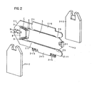
- these pressure tappet units consist of a flat frame 2-1-1 between whose legs a tongue-shaped tappet 5 runs in a recess (see FIGS. 1 and 2 of this application GE 980 048 ).
- a print head 5-1 is attached.
- the pressure plunger 5 can move in the pressure direction D marked by the arrow (or opposite thereto). His lateral movement is through prevents the electromagnetic drive units 2-1-2 and 2-1-3 attached to the frame.
- These electromagnetic drive units can be attached to the frame by gluing, screwing, riveting or other conventional methods.
- two holes 6 are made; Likewise, two holes 9 are provided in the rear base part of the U-shaped frame.
- holes 6 and 9 are used to hang two tension springs 7, which bring the deflected plunger back to its starting position.
- the starting position is formed by a stop 8.
- a pin 11, which is designed as an extension of the stop 8, is fastened in the direction of D in the base of the U-shaped frame.
- the plunger is accelerated in the direction of action D by activating the electromagnetic drive units.
- the pressure tappet is returned to its starting position by the force of the springs 7.
- the disadvantages of the electromagnets are based on the following:
- the U-shaped or the magnet yokes connected in series to form combs carry the windings on their base part.
- Comb-like magnetic yoke arrangements are known from German patent application P 30 18 407.7 (GE 980 014), as explained in more detail in connection with FIG. 7 of this application GE 980 048.
- GE 980 014 German patent application P 30 18 407.7
- This fact has a particularly disadvantageous effect for the desired high division density of such tappet units in a bank.
- the application of the coils to the magnetic yokes is cumbersome and costly, and the outer coil parts lead to an undesirable magnetic interaction with the neighboring units.
- the soft iron web structure in the tongue-shaped tappet specified in the exemplary embodiment according to P 29 26 276.8 also has a number of disadvantages. These disadvantages lie in the difficulty of simply inserting such individual soft iron webs into the tongue-shaped pressure tappet body, which otherwise consists of plastic, while observing all the required tolerances.
- the improvements are said to lie in the spatial design of the electromagnet units and in the web structures to be inserted in the tongue-shaped pressure tappet body, and in a reduced interaction of neighboring electromagnet units.
- FIG. 3 is a schematic perspective view of an electromagnetic pressure ram drive according to the German patent application P 29 26 276.8 shown.
- a tongue 18 movable in the direction of arrow D is arranged between two fixed stator halves 25, 22.
- the stator halves 25 and 22 each consist of a magnetizable yoke 27 and 24, which is surrounded by coil turns 26 and 23, respectively.
- the stator yokes can e.g. B. be semicircular, semi-elliptical or U-shaped.
- the stator yokes 27, 24 in the two stator halves 25 and 22 are aligned such that the respective opposite yoke ends are aligned.
- the magnetic flux runs from a yoke over a working gap, in which an armature web 20 is arranged, to the yoke of the other stator half and from there via a further working gap back to the former yoke, so that the magnetic circuit runs out the two stator yokes and the two working columns located between the ends of the stator yokes.
- stator pair instead of a stator half pair in the opposing stator halves.
- the current flow in the excitation coils 26 and 23 takes place in such a way that the current direction in the windings within the two opposing stator yokes is the same and opposite to that in the windings outside the stator yokes.
- the windings are indicated schematically by a few wire loops in the front part of the illustration, while a corresponding sectional illustration of the wires was selected in the rear part.
- the tongue 18 arranged movably in the direction of arrow D between the stator halves 25 and 22 is expanded in the direction of the working gap to be much smaller than in its other two dimensions.
- the body of the tongue 18 consists of a light, magnetically non-conductive material 19 and magnetically conductive, so-called anchor webs 20 and 21.
- Anchor bars are arranged in the tongue 18 such that they are drawn into the space formed between the stator yokes when the stator halves are excited from a rest-starting position and thereby accelerated. The tongue can then follow a further movement in the direction of arrow D.
- the design of the anchor webs 20 and 21 is essentially chosen so that their volume would approximately fill the space circumscribed between the ends of the opposite stator yokes.
- the distance covered by the tongue from the starting position to the position after the end of the acceleration phase (when the anchor bridge is in the working gap) is called the acceleration stroke; the sum of the acceleration stroke and the subsequent further deflection of the tongue in the direction of arrow D as the working stroke.
- This size depends on the structural boundary conditions and on the means provided for storing the tongue or for returning the tongue to its initial position.
- return springs can be used: z.
- electromagnet described in German patent application P 30 18 407.7 (GE 980 014) with a working gap, into which an element containing a displaceable soft magnetic material is drawn when the electromagnet is excited is characterized in that the electromagnet (95) consists of two magnetizable yoke halves (96 , 97, 99; 108, 109, 98), of which at least one is enclosed by a coil (100), that the mutually facing, essentially semicircular, recessed pole ends of the yoke halves form essentially circular working gaps (101, 102), that between the pole ends of the yoke halves a plunger (91) which is displaceable in the direction of the line of alignment of the working gap and which has a cross section which is adapted to the surface of the working gap, that the plunger (91) has two armature disks (92, 93) made of magnetizable material and one between them Armature disks (92, 93) arranged spacer element (94) made predominantly non-magnetized
- FIG. 1 shows a perspective view of a bench for accommodating a plurality of pressure ram units.
- the pressure tappet units of which only four (for the sake of simplicity) (without the pressure tappet) are shown with 2-1, 2-2, 2-3 and 2-4.
- the frames of these pressure tappet units bear the reference numbers 2-1-1, 2-2-1, 2-3-1 and 2-4-1.
- Each pressure tappet unit has a pair of electromagnetic drive units for the pressure tappet.
- the electromagnetic drive units for the pressure ram unit 2-1 are designated 2-1-2 and 2-1-3 and are arranged on both sides of the frame 2-1-1 in an aligned manner.
- Electromagnetic drive units as can be used for the bank described here, are described in German patent application P 29 26 276.8.
- the print hammer bank consists of a lower part 1-1 and an upper comb-like part 1-2.
- the lower part 1-1 is referred to as the base part and the upper part 1-2 as the comb part.
- the base part is composed of two rails 1-1-1, 1-1-2 running parallel to one another and a part 1-1-3 provided with slots 4 between them.
- the slots run parallel to each other and are limited in length by the rails 1-1-1 and 1-1-2. They serve to accommodate a lower extension (see FIGS. 2 and 4) of the pressure tappet frame.
- the comb part 1-2 of the bench consists of a beveled (1-2-1) part which has comb-like incisions 3 on its side tapered by the bevel. These comb-like incisions 3 are aligned with the slots 4 in the base part 1-1. Each of these comb-like cuts 3 ⁇ m takes part of the upper edge of the frame of the individual plunger units. The individual plunger units are thus fixed in their position.
- a vertical evasion is by the position of D jerk plunger assemblies between the base member 1-1 and the crest part 1-2 not possible during an evasion in direction of action of the pressure ram (not shown) parallel to the extending direction of the slits 4 and opposite thereto by means of corresponding receiving the lower frame approach (2-1-7; 14) in the slots 4 can be prevented or influenced in the desired manner.
- the latter is particularly important for those cases in which you want to cause the plunger to rebound against the pressure hammer bench. Further details are given in connection with FIG. 2.
- an electromagnetic drive unit 2-1-2 and 2-1-3 is arranged in a mutually aligned form.
- the electromagnetic drive units are offset in pairs for side-by-side pressure tappet units, so that the distance between two adjacent frames is determined by the strength of an electromagnetic drive unit.
- the electromagnetic drive units 2-1-2 / 2-1-3 of the pressure tappet units 2-1 are compared to the electromagnetic drive units 2-2-2 / 2-2-3 of the pressure tappet unit 2 -2 offset accordingly.
- FIG. 1 and FIG. 2 originate from the German patent application GE 980 052, which was filed on the same day as the present German patent application GE 980 048.
- FIG. 4 shows an exploded drawing of a pressure ram unit with associated electromagnetic drive units. Many parts of Fig. 4 correspond to the parts with the same reference numerals in Figs. 1 and 2. In order to avoid repetitions, they are not dealt with in the explanation of FIG. 4 or only briefly.
- the tongue-shaped plunger 5 the base body of which is made of plastic, is provided with bores 31 at various points for reasons of weight.
- the soft iron bars required for the effectiveness of the electromagnetic drive are shown at 60, 61 and 62.
- the electromagnetic drive units 2-1-2 and 2-1-3 which are fastened on both sides of the frame 2-1 in an aligned form, each contain a magnetic yoke 41 (51) and an associated excitation coil 45 (55).
- the magnet yoke coil combinations are marked with 40 and 50. Each of these combinations is received by a housing 140, 150 with a corresponding plug connection 141, 151 with contacts 142, 152 for the excitation coils 45 and 55.
- These housings are connected to the frame by means of screws (not shown) or other suitable fastening means.
- Corresponding mounting holes are designated in the housing 150 with 32-1 and 33-1 and in the frame 2-1 with 32 and 33.
- the from Fastening elements not shown for reasons of clarity, ensure exact positioning of the electromagnetic drive units, in particular the working gap in relation to the soft iron webs 6, 19, 20 in the tongue-shaped tappet 5.
- a magnetizable web does not have to be in the excited state of the electromagnets in front of a working gap.
- the magnet yokes 41 and 51 have an E-shaped cross section.
- the opposite E-shaped magnet yokes 51 and 41 are aligned so that a total of 3 working gaps are formed by their leg ends 52, 53, 54 and 42, 43, 44: the first working gap is between the leg ends 52 and 42, the second between the Leg ends 53 and 43 and the third between the leg ends 54 and 44.
- One of the three magnetizable webs 62, 61 and 60 is assigned to each of these working gaps.
- the excitation winding for each magnetic yoke runs, as shown in FIG. 4, around the middle E-leg in such a way that the excitation coil can be manufactured separately as a flat slip-on coil for the middle E-leg, with the winding strands running parallel in the through the E- Legs formed spaces must fit.
- the magnetic yoke excitation coils is extremely inexpensive and space-saving.
- the coil expansion does not extend in the direction perpendicular to the plunger plane beyond the magnetic yoke. This fact is particularly noteworthy for a high packing density with little magnetic interaction of the pressure tappet units in banks.
- the flat coil and the E-shaped magnetic yoke allow simple and inexpensive production of the individual parts and easy assembly of the two parts.
- the magnetic yoke coil combination 50 is inserted into a corresponding recess 34 in the housing 150 and is potted there with the housing with plastic. The same applies to the magnet yoke coil combination 40 and the housing 140.
- the soft iron webs in the pressure ram 5 should in particular be assigned as tolerance-free as possible to the corresponding working gaps of the electromagnets. This also results in requirements for the most problem-free insertion of the magnetizable webs into the plastic base body of the plunger 5.
- FIG. 5 shows a structure in which the magnetizable webs 60, 61 and 62 are continuously connected with the same magnetizable material of thinner thickness.
- the webs 60 and 61 are connected via the connection 63 and the webs 61 and 62 via the connection 64.
- Such connections 63, 64 between the webs are undesirable for optimal operation of the drive. It has been found, however, that with a correspondingly thin strength of these compounds, their disadvantageous influence on the efficiency is only slight and that this influence can be accepted in practice without further ado.
- FIG. 6 Another web structure is shown in FIG. 6.
- the plunger itself is labeled 70, the plunger head again 5-1.
- the holes for receiving the tension springs (not shown) (see FIG. 4) have the reference number 6 and those material-saving bores have the reference number 31 as in FIG. 4.
- the web structure 71 itself has the shape of a longitudinally and transversely divided rectangular frame with four openings 72.
- the frame parts essential for the tappet drive are the webs 73, 74 and 75.
- the webs 73 and 74 are due to the frame parts 76, 77 and 78 lying transversely thereto made of the same material as the web material;
- the webs 74 and 75 are connected by the frame parts (same material) 79, 80 and 81 lying transversely thereto.
- the transverse frame parts are narrower and thinner than the webs themselves - the frame openings are encapsulated with plastic up to the ram level.
Landscapes
- Physics & Mathematics (AREA)
- Electromagnetism (AREA)
- Electromagnets (AREA)
- Reciprocating, Oscillating Or Vibrating Motors (AREA)
Abstract
Description
- Die Erfindung betrifft einen elektromagnetischen Stößelantrieb, bei dem der Elektromagnet aus zwei symmetrisch aufgebauten, von jeweils einer Spule umfaßten, magnetisierbaren Jochhälften besteht, deren einander zugewandte Polenden einander fluchtende Arbeitsspalte bilden und bei dem zwischen den Arbeitsspalten ein in Richtung der Fluchtlinie der Arbeitsspalte verschiebbarer zungenförmiger Stößel angeordnet ist, welcher Ankerstege aus magnetisierbarem Material aufweist, von denen jeder einem Arbeitsspalt zugeordnet ist und wobei das Volumen der Ankerstege in der Größenordnung des Arbeitsspaltvolumens liegt und die Ankerstege in der Ausgangslage des Stößels im nichterregten Zustand des Elektromagneten sich vor dessen Arbeitsspalten befindet und bei Erregung des Elektromagnets in dessen Arbeitsspalte hineingezogen werden.
- Ein derartiger elektromagnetischer Stößelantrieb wie er in der deutschen Patentanmeldung P 29 26 2 76.8 (GE 979 026) beschrieben wurde, ist insbesondere zur Anwendung in Anschlagdruckern geeignet.
- In der deutschen Patentanmeldung GE 980 052, welche am gleichen Tage mit der hier vorliegenden Patentanmeldung GE GE 980 048 prioritätbegründend eingereicht wurde, ist eine Bank zur Aufnahme mehrerer Druckstößeleinheiten beschrieben.
- Diese Druckstößeleinheiten bestehen, wie in P 29 26 276.8 beschrieben und dargestellt, aus einem flachen Rahmen 2-1-1 zwischen dessen Schenkeln in einer Aussparung ein zungenför- miger Stößel 5 verläuft (siehe Fig. 1 und Fig. 2 dieser Anmeldung GE 980 048). Am Aktionsende dieses Stößels 5 ist ein Druckkopf 5-1 befestigt. Der Druckstößel 5 kann sich in der durch den Pfeil markierten Druckrichtung D (bzw. dazu entgegengesetzt) bewegen. Seine seitliche Bewegung ist durch die am Rahmen befestigten elektromagnetischen Antriebseinheiten 2-1-2 und 2-1-3 verhindert. Die Anbringung dieser elektromagnetischen Antriebseinheiten am Rahmen kann durch Kleben, Schrauben, Nieten oder andere herkömmliche Methoden erfolgen. Am hinteren Ende des zungenförmigen Stößels 5 sind zwei Bohrungen 6 angebracht; ebenso sind im hinteren Basisteil des u-förmigen Rahmens zwei Bohrungen 9 vorgesehen. Diese Bohrungen 6 und 9 dienen zum Einhängen zweier Zugfedern 7, die den ausgelenkten Druckstößel in seine Ausgangslage zurückbringen. Die Ausgangslage wird durch einen Anschlag 8 gebildet. In der Basis des u-förmigen Rahmens ist in Richtung D ausgerichtet ein Stift 11 befestigt, der als Fortsatz des Anschlags 8 ausgebildet ist. Durch Aktivieren der elektromagnetischen Antriebseinheiten wird der Stößel in Aktionsrichtung D beschleunigt. Nach erfolgtem Anschlag auf die nicht dargestellte Drucktype oder den nicht dargestellten Aufzeichnungsträger wird der Druckstößel durch die Kraft der Federn 7 wieder in seine Ausgangslage zurückgeführt.
- Das Prinzip des elektromagnetischen Antriebs, welches auch dem hier vorliegenden Anmeldungsgegenstand zugrunde liegt, ist in der deutschen Patentanmeldung P 29 26 276.8 (GE 979 026) beschrieben. Die in dieser Anmeldung beschriebene Ausführungsform der Elektromagnetpaare und die Ausführung der Weicheisenstegstruktur in dem zungenförmigen Stößel weisen jedoch eine Reihe von Nachteilen auf.
- Die Nachteile der Elektromagnete liegen in folgendem begründet: Die u-förmigen bzw. die zu Kammgebilden hintereinander geschalteten Magnetjoche tragen die Wicklungen auf ihrem Basisteil. Kammartige Magnetjochanordnungen sind aus der deutschen Patentanmeldung P 30 18 407.7 (GE 980 014) bekannt, wie im Zusammenhang mit Fig. 7 dieser Anmeldung GE 980 048 näher ausgeführt. Dadurch ergibt sich eine größere räumliche Ausdehnung der Elektromagneteinheiten in Richtung senkrecht zur Ebene des zungenförmigen Stößels. Dieser Umstand wirkt sich besonders nachteilig für eine erstrebte hohe Teilungsdichte solcher Stößeleinheiten in einer Bank aus. Des weiteren ist die Aufbringung der Spulen auf die-Magnetjoche umständlich und kostenaufwendig, und die außen liegenden Spulenteile führen zu einer unerwünschten magnetischen Wechselwirkung mit den Nachbareinheiten.
- Die im Ausführungsbeispiel nach P 29 26 276.8 angegebene Weicheisenstegstruktur im zungenförmigen Stößel ist ebenfalls mit einer Reihe von Nachteilen behaftet. Diese Nachteile liegen in der Schwierigkeit, solche einzelnen Weicheisenstege einfach unter Einhaltung aller erforderlichen Toleranzen in den sonst aus Kunststoff bestehenden zungenförmigen Druckstößelkörper einzubringen.
- Es ist deshalb Aufgabe der vorliegenden Erfindung, einen elektromagnetischen Stößelantrieb unter Vermeidung vorgenannter Nachteile vorzusehen.
- Die Verbesserungen sollen in der räumlichen Ausbildung der Elektromagneteinheiten und der in den zungenförmigen Druckstößelkörper einzusetzenden Stegstrukturen liegen sowie in einer verringerten Wechselwirkung benachbarter Elektromagneteinheiten.
- Diese Aufgabe der Erfindung wird in vorteilhafterweise durch die im kennzeichnenden Teil des Anspruches 1 genannten Maßnahmen gelöst.
- Vorteilhafte Weiterbildungen der Erfindung sind den Unteransprüchen zu entnehmen.
- Ein Ausführungsbeispiel der Erfindung ist in den Zeichnungen dargestellt und wird im folgenden näher beschrieben.
- Es zeigen:
- Fig. 1 eine perspektivische vereinfachte Darstellung einer Bank zur Aufnahme mehrerer Druckstößeleinheiten gemäß GE 980 052,
- Fig. 2 eine vereinfachte perspektivische Exposionszeichnung einer Druckstößeleinheit mit den ihr zugeordneten beidseits ihres Rahmens angeordneten elektromagnetischen Antriebseinheiten für den zungenförmigen Stößel,
- Fig. 3 eine schematische vereinfachte Darstellung zum Prinzip des Druckstößelantriebes gemäß der deutschen Patentanmeldung P 29 26 276'.8 (GE 979 026),
- Fig. 4 eine Explosionszeichnung einer Druckstößeleinheit mit zugehörigen elektromagnetischen Antriebseinheiten,
- Fig. 5 eine Schnittdarstellung durch die Stegstruktur entlang der Schnittlinie A-A in Fig. 4,
- Fig. 6 ein zungenförmiger Stößel mit einer anderen Ausführungsform der magnetischen Stege als in Fig. 4 und Fig. 5,
- Fig. 7 eine schematische perspektivische Prinzipdarstellung eines Stößelantriebes, bei dem ein zylinderförmiger Druckstößel in den kreisförmig ähnlichen Arbeitsspalten zweier gegenüberliegender Jochhälften verläuft.
- In Fig. 3 ist eine schematische perspektivische Darstellung eines elektromagnetischen Druckstößelantriebes gemäß der deutschen Patentanmeldung P 29 26 276.8 gezeigt. Zwischen zwei fest angeordneten Statorhälften 25, 22 ist eine in Richtung des Pfeiles D bewegliche Zunge 18 angeordnet. Die Statorhälften 25 und 22 bestehen jeweils aus einem magnetisierbaren Joch 27 bzw. 24, welches von Spulenwindungen 26 bzw. 23 umfaßt ist. Die Statorjoche können-z. B. halbkreisförmig, halbellipsenförmig oder auch u-förmig ausgebildet sein. Die Statorjoche 27, 24 in den beiden Statorhälften 25 und 22 sind derart ausgerichtet, daß die jeweils gegenüberliegenden Jochenden fluchten. Bei Erregung der Spulen 26 und 23 verläuft der magnetische Fluß von einem Joch über einen Arbeitsspalt, in welchem ein Ankersteg 20 angeordnet ist, zum Joch der anderen Statorhälfte und von dort aus über einen weiteren Arbeitsspalt zum erstgenannten Joch zurück, so daß der magnetische Kreis aus den beiden Statorjochen und den zwischen den Enden der Statorjoche befindlichen zwei Arbeitsspalten besteht.
- Im folgenden soll aus Vereinfachungsgründen bei den einander gegenüberliegenden Statorhälften von einem Statorpaar (anstelle eines Statorhälftenpaares) gesprochen werden.
- Der Stromfluß in den Erregerspulen 26 und 23 erfolgt derart, daß die Stromrichtung in den Windungen innerhalb der beiden einander gegenüberliegenden Statorjoche die gleiche und entgegengesetzt zu derjenigen in den Windungen außerhalb der Statorjoche ist. In Fig. 3 sind im vorderen Teil der Darstellung die Windungen schematisch durch einige Drahtschleifen angedeutet, während im hinteren Teil eine entsprechende Schnittdarstellung der Drähte gewählt wurde. Die zwischen den Statorhälften 25 und 22 in Pfeilrichtung D beweglich angeordnete Zunge 18 ist in Richtung des Arbeitsspaltes ungleich kleiner ausgedehnt als in ihren anderen beiden Dimensionen. Der Körper der Zunge 18 besteht aus einem leichten, magnetisch nicht leitenden Material 19 und magnetisch leitenden, sog. Ankerstegen 20 und 21. Diese Ankerstege sind in der Zunge 18 so angeordnet, daß sie bei Erregung der Statorhälften aus einer Ruhe-Ausgangs-Lage in den zwischen den Statorjochen gebildeten Raum hineingezogen und dabei beschleunigt werden. Danach kann die Zunge einer weiteren Bewegung in Pfeilrichtung D folgen. Die Ausbildung der Ankerstege 20 und 21 ist im wesentlichen so gewählt, daß sie mit ihrem Volumen den zwischen den Enden gegenüberliegender Statorjoche umschriebenen Raum in etwa ausfüllen würden.
- Die durch die Zunge zurückgelegte Wegstrecke von der Ausgangsstellung bis zur Stellung nach Abschluß der Beschleunigungsphase (wenn sich der Ankersteg im Arbeitsspalt befindet) wird als Beschleunigungshub bezeichnet; die Summe aus Beschleunigungshub und der danachfolgenden weiteren Auslenkung der Zunge in Richtung des Pfeiles D als Arbeitshub. Diese Größe ist von konstruktiven Randbedingungen abhängig sowie von den zur Lagerung der Zunge bzw. zur Rückführung der Zunge in seine Ausgangsstellung vorgesehenen Mitteln. Als solche Mittel können an sich bekannte Rückstellfedern (nicht dargestellt) verwendet werden: z. B. zwei Blattfedern, wie in der DAS 12 37 816 beschrieben: eine Feder im Zusammenwirken mit einer Gleitlagerung der Zunge oder eine Rückholfeder im Zusammenwirken mit einer schwenkbar um eine Achse bewegbaren Zunge. Auch eine elektromagnetisch bedingte Rückführung ist möglich.
- Aus der Darstellung in Fig. 3 ist ersichtlich, daß die Spulenwindungen um die Basis der u-förmigen Jochhälften verlaufen. Mit anderen Worten, die Windungen sind innnerhalb und außerhalb des Jochpaares angeordnet sind. Der Aufwand zur Anbringung solcher Wicklungen sowie der damit verbundene Raumbedarf sind relativ hoch. Zur Vermeidung dieser Nachteile macht deshalb der Gegenstand der vorliegenden Anmeldung insbesondere von einer erfindungsgemäßen Ausbildung der Jochhälften im Zusammenhang mit der Anbringung der Wicklungen Gebrauch.
- In diesem Zusammenhang sei darauf hingewiesen, daß die in der deutschen Patentanmeldung P 30 18 407.7 (GE 980 014) gemäß der Darstellung nach Fig. 7 u-förmigen Jochhälften auch hintereinander geschaltet sein können, wobei jedoch die Erregerwicklung auch dort wiederum nur deren Basis umfaßt.
- Ein in der deutschen Patentanmeldung P 30 18 407.7 (GE 980 014) beschriebener Elektromagnet mit Arbeitsspalt, in den bei Erregung des Elektromagneten ein verschiebbares weichmagnetisches Material enthaltende Element hineingezogen wird, ist dadurch gekennzeichnet, daß der Elektromagnet (95) aus zwei magnetisierbaren Jochhälften (96, 97, 99; 108, 109, 98) besteht, von denen mindestens eine von einer Spule (100) umfaßt ist, daß die einander zugewandten im wesentlichen halbkreisförmig ausgesparten Polenden der Jochhälften miteinander fluchtende im wesentlichen kreisförmige Arbeitsspalte (101, 102) bilden, daß zwischen den Polenden der Jochhälften ein in Richtung der Fluchtlinie der Arbeitsspalte verschiebbarer Stößel (91) mit einem an die Fläche der Arbeitsspalte angepaßten Querschnitt angeordnet ist, daß der Stößel (91) zwei Ankerscheiben (92, 93) aus magnetisierbarem Material und ein zwischen diesen Ankerscheiben (92, 93) angeordnetes Distanzelement (94) aus überwiegend nicht magnetisierbarem Material aufweist, daß jedem Arbeitsspalt (101, 102) eine Ankerscheibe (92, 93) zugeordnet ist, daß die Ankerscheiben (92, 93) eine derartige geometrische Ausbildung aufweisen, daß ihre Volumen in der Größenordnung des Raumes zwischen den einander zugewandten Polenden der Jochhälften liegt, und daß sich die Ankerscheiben (92, 93) in der Ausgangslage des Stößels (91) im nichterregten Zustand des Elektromagneten vor dessen Arbeitsspalten (101, 102) befinden und bei Erregung des Elektromagneten in diese Arbeitsspalte hineingezogen werden.
- In Fig. 1 ist eine perspektivische Ansicht einer Bank zur Aufnahme mehrerer Druckstößeleinheiten gezeigt. Die Druckstößeleinheiten, von denen aus Vereinfachungsgründen nur vier Stück (ohne die Druckstößel) dargestellt sind, sind mit 2-1, 2-2, 2-3 und 2-4 bezeichnet. Die Rahmen dieser Druckstößeleinheiten tragen die Bezugszeichen 2-1-1, 2-2-1, 2-3-1 und 2-4-1. Zu jeder Druckstößeleinheit gehört ein Paar elektromagnetischer Antriebseinheiten für den Druckstößel. Die elektromagnetischen Antriebseinheiten für die Druckstößeleinheit 2-1 sind mit 2-1-2 und 2-1-3 bezeichnet und beidseits des Rahmens 2-1-1 in zueinander ausgerichteter Form angeordnet.
- Elektromagnetische Antriebseinheiten, wie sie für die hier beschriebene Bank Verwendung finden könne, sind in der deutschen Patentanmeldung P 29 26 276.8 beschrieben.
- Aus der Darstellung in Fig. 1 ist ersichtlich, wie die einzelnen Druckstößeleinheiten in der Druckhammerbank Aufnahme finden. Die Druckhammerbank besteht aus einem unteren Teil 1-1 und einem oberen kammartigen Teil 1-2. Im folgenden wird der untere Teil 1-1 als Basisteil und der obere Teil 1-2 als Kammteil bezeichnet. Das Basisteil ist aus zwei parallel zueinander verlaufenden Schienen 1-1-1, 1-1-2 und einem zwischen diesen beiden liegenden mit Schlitzen 4 versehenen Teil 1-1-3 zusammengesetzt. Die Schlitze verlaufen parallel zueinander und sind durch die Schienen 1-1-1 und 1-1-2 in ihrer Längsausdehnung begrenzt. Sie dienen der Aufnahme jeweils eines unteren Ansatzstückes (siehe Fig. 2 und Fig. 4) der Druckstößelrahmen.
- Das Kammteil 1-2 der Bank besteht aus einem abgeschrägten (1-2-1) Teil, welches an seiner durch die Schräge verjüngten Seite kammartige Einschnitte 3 aufweist. Diese kammartigen Einschnitte 3 sind auf die Schlitze 4 im Basisteil 1-1 ausgerichtet. Jeder dieser kammartigen Einschnitte 3 umfaßt einen Teil des oberen Randes der Rahmen der einzelnen Druckstößeleinheiten. Somit sind die einzelnen Druckstößeleinheiten in ihrer Lage fixiert. Ein seitliches Ausweichen wird durch die Schlitze 4 bzw. die kammartigen Einschnitte 3 verhindert; ein vertikales Ausweichen ist durch die Lage der Druckstößeleinheiten zwischen dem Basisteil 1-1 und dem Kammteil 1-2 nicht möglich, während ein Ausweichen in Aktionsrichtung des Druckstößels (nicht dargestellt) parallel zur Verlaufsrichtung der Schlitze 4 bzw. entgegengesetzt dazu durch entsprechende Aufnahme des unteren Rahmenansatzes (2-1-7; 14) in die Schlitze 4 verhindert oder in gewünschter Weise beeinflußt werden kann. Letzteres ist besonders für jene Fälle wichtig, in denen man einen abgefederten Rückstoß des Stößels auf die Druckhammerbank bewirken möchte. Nähere Angaben hierzu werden im Zusammenhang mit Fig. 2 gemacht.
- Es wurde bereits erwähnt, daß beidseits des Rahmens, z. B. 2-1-1 der Druckstößeleinheit 2-1, eine elektromagnetische Antriebseinheit 2-1-2 und 2-1-3 in zueinander ausgerichteter Form angeordnet ist. Zur Erreichung einer engen Packungsdichte der Druckstößel in der Bank sind für nebeneinanderliegende Druckstößeleinheiten die elektromagnetischen Antriebseinheiten paarweise versetzt, so daß der Abstand zweier nebeneinanderliegender Rahmen von der Stärke einer elektromagnetischen Antriebseinheit bestimmt wird. Wie aus der Darstellung in Fig. 1 zu ersehen ist, sind die elektromagnetischen Antriebseinheiten 2-1-2/2-1-3 der Druckstößeleinheiten 2-1 gegenüber den elektromagnetischen Antriebseinheiten 2-2-2/2-2-3 der Druckstößeleinheit 2-2 entsprechend versetzt.
- Aus Gründen der Übersicht sind die elektromagnetischen Antriebseinheiten für die Druckstößeleinheit 2-3 nicht in Fig. 1 dargestellt.
- Die Darstellungen in Fig. 1 und Fig. 2 entstammen der deutschen Patentanmeldung GE 980 052, die am gleichen Tage wie die hier vorliegende deutsche Patentanmeldung GE 980 048 eingereicht wurde.
- Während sich die Anmeldung GE 980 052 auf eine Bank zur Aufnahme von Druckstößeleinheiten bezieht, werden in der hier vorliegenden Anmeldung GE 980 048 die Besonderheiten in der Ausbildung der elektromagnetischen Antriebseinheiten für die Druckstößeleinheiten beschrieben. Einzelheiten dazu sind in den Fign. 4, 5 und 6 wiedergegeben.
- In Fig. 4 ist eine Explosionszeichnung einer Druckstößeleinheit mit zugehörigen elektromagnetischen Antriebseinheiten dargestellt. Viele Teile der Fig. 4 entsprechen den Teilen mit den gleichen Bezugszeichen in den Fign. 1 und 2. Zur Vermeidung von Wiederholungen wird auf sie bei Erläuterung von Fig. 4 nicht oder nur kurz eingegangen.
- Der zungenförmige Stößel 5, dessen Grundkörper aus Kunststoff besteht, ist an verschiedenen Stellen aus Gewichtsgründen mit Bohrungen 31 versehen. Die für die Wirksamkeit des elektromagnetischen Antriebes erforderlichen Weicheisenstege sind mit 60, 61 und 62 dargestellt. Die elektromagnetischen Antriebseinheiten 2-1-2 und 2-1-3, die beidseits des Rahmens 2-1 in einander ausgerichteter Form befestigt sind, enthalten jeweils ein Magnetjoch 41 (51) und eine zugehörige Erregerspule 45 (55). Die Magnetjochspulenkombinationen sind mit 40 und 50 gekennzeichnet. Jede dieser Kombination wird von einem Gehäuse 140, 150 aufgenommen mit einem entsprechenden Steckeranschluß 141, 151 mit den Kontakten 142, 152 für die Erregerspulen 45 und 55. Diese Gehäuse sind mittels nicht dargestellter Schrauben oder anderer geeigneter Befestigungsmittel mit dem Rahmen verbunden. Entsprechende Befestigungslöcher sind im Gehäuse 150 mit 32-1 und 33-1 und im Rahmen 2-1 mit 32 und 33 bezeichnet. Die aus Übersichtsgründen nicht dargestellten Befestigungselemente sorgen für eine exakte Positionierung der elektromagnetischen Antriebseinheiten, insbesondere der Arbeitsspalte in Bezug auf die Weicheisenstege 6, 19, 20 in dem zungenförmigen Stößel 5. Wie im Zusammenhang mit der Patentanmeldung P 29 26 276.8 erwähnt, muß ein magnetisierbarer Steg im nicht erregten Zustand der Elektromagnete vor einem Arbeitsspalt stehen.
- Im vorliegenden Fall haben die Magnetjoche 41 und 51 einen E-förmigen Querschnitt. Die gegenüberliegenden E-förmigen Magnetjoche 51 und 41 sind so aufeinander ausgerichtet, daß durch ihre Schenkelenden 52, 53, 54 und 42, 43, 44 insgesamt 3 Arbeitsspalte gebildet werden: Der erste Arbeitsspalt liegt zwischen den Schenkelenden 52 und 42, der zweite zwischen den Schenkelenden 53 und 43 und der dritte zwischen den Schenkelenden 54 und 44. Jedem dieser Arbeitsspalte ist einer der drei magnetisierbaren Stege 62, 61 und 60 zugeordnet. Die Erregerwicklung für jedes Magnetjoch verläuft, wie in Fig. 4 dargestellt, um den mittleren E-Schenkel so, daß die Erregerspule separat als flache Aufsteckspule für den mittleren E-Schenkel gefertigt werden kann, wobei die parallel verlaufenden Wicklungsstränge in die durch die E-Schenkel gebildeten Zwischenräume passen müssen.
- Diese spezielle Ausgestaltung der Magnetjoch-Erregerspulen ist äußerst kostengünstig und raumsparend. Die Spulenausdehnung reicht nicht in Richtung senkrecht zur Stößelebene über das Magnetjoch hinaus. Dieser Umstand ist besonders für eine hohe Packungsdichte bei geringer magnetischer Wechselwirkung der Druckstößeleinheiten in Bänken beachtenswert. Außerdem läßt die Flachspule und das E-förmige Magnetjoch eine einfache und kostengünstige Herstellung der Einzelteile und ein problemloses Zusammensetzen beider Teile zu. Die Magnetjochspulenkombination 50 wird in eine entsprechende Aussparung 34 des Gehäuses 150 eingefügt und dort mit dem Gehäuse mit Kunststoff vergossen. Analoges gilt für die Magnetjochspulenkombination 40 und das Gehäuse 140. Es sei an dieser Stelle ausdrücklich betont, daß für eine exakte Arbeitsweise des Druckstößelantriebes insbesondere eine möglichst toleranzfreie Zuordnung der Weicheisenstege im Druckstößel 5 zu den entsprechenden Arbeitsspalten der Elektromagnete erfolgen soll. Hierdurch ergeben sich auch Forderungen für ein möglichst problemloses Einfügen der magnetisierbaren Stege in den Kunststoffgrundkörper des Stößels 5.
- Es kann grundsätzlich davon ausgegangen werden, daß sich diese Stege relativ einfach in den Kunststoffkörper einfügen und mit ihm vergießen lassen. Problematischer hingegen ist im wesentlichen eine exakte Anordnung der Stege zueinander. Aus diesem Grunde sollen die Stege nicht einzeln in den Stößel eingefügt werden, sondern als ein zusammenhängendes gemeinsames Teil. Für die Struktur eines solchen Teiles gibt es verschiedene Alternativen, wie z. B. in den Fign. 5 und 6 dargestellt.
- In Fig. 5 ist eine Struktur gezeigt, bei der die magnetisierbaren Stege 60, 61 und 62 durchgehend mit gleichem magnetisierbarem Material dünnerer Stärke verbunden sind. So hängen die Stege 60 und 61 über die Verbindung 63 und die Stege 61 und 62 über die Verbindung 64 zusammen. Solche Verbindungen 63, 64 zwischen den Stegen sind für eine optimale Wirkungsweise des Antriebs unerwünscht. Es hat sich jedoch herausgestellt, daß bei entsprechend dünner Stärke dieser Verbindungen deren nachteiliger Einfluß auf den Wirkungsgrad nur gering ist und daß dieser Einfluß praktisch gesehen ohne weiteres in Kauf genommen werden kann. Dadurch ist es möglich, die Stegstruktur als zusammenhängendes Teil herzustellen und eine einfache Einbettung dieses Teiles in den zungenförmigen Stößel 5 zu bewirken. Hierbei hat man nur die maßgerechte Einpassung dieses einen Teiles in den Stößel 5 zu berücksichtigen (und nicht die dreier Einzelstege). Nach dem Einfügen dieses Teiles in eine entsprechende Aussparung des Stößels erfolgt ein Vergießen mit Kunststoff, wobei auch die bisher leeren Aussparungen (64, 65) des Teiles bis zur Stößelebene mit Kunststoff ausgegossen werden.
- In Fig. 6 ist eine andere Stegstruktur gezeigt. Der Stößel selbst ist mit 70, der Stößelkopf wieder mit 5-1 bezeichnet. Die Löcher zur Aufnahme der nicht dargestellten Zugfedern (s. Fig. 4) haben das Bezugszeichen 6 und jene materialeinsparenden Bohrungen haben wie auch in Fig. 4 das Bezugszeichen 31.
- Die Stegstruktur 71 selbst hat die Form eines längs- und quergeteilten rechteckigen Rahmens mit vier Öffnungen 72. Die für den Stößelantrieb wesentlichen Rahmenteile sind die Stege 73, 74 und 75. Die Stege 73 und 74 sind durch die dazu querliegenden Rahmenteile 76, 77 und 78 aus gleichem Material wie das Stegmaterial verbunden; ebenso sind die Stege 74 und 75 durch die dazu querliegenden Rahmenteile (gleichen Materials) 79, 80 und 81 verbunden. Die querliegenden Rahmenteile sind schmaler und dünner als die Stege selbst - die Rahmenöffnungen werden bis zur Stößelebene mit Kunststoff vergossen.
Claims (5)
dadurch gekennzeichnet,
daß die Jochhälften (41, 51) senkrecht zur Stößelebene einen E-förmigen Querschnitt aufweisen und die Windungen (45, 55) der die Jochhälften (41, 51) erregenden Spulen (45, 55; 54, 53; 53, 52) im wesentlichen zwischen den E-Schenkeln (44, 43; 43, 41) verlaufen.
dadurch gekennzeichnet,
daß die Ankerstege (60, 61, 62, 73, 74, 75) durch Brücken (63, 64, 76, 77, 78, 79, 80, 81) gleichen magnetisierbaren Materials, aus dem sie selbst bestehen, miteinander verbunden sind und ein zusammenhängendes Teil bilden.
dadurch gekennzeichnet,
daß die Brücken (63, 64, 76, 78, 79, 81) nicht so breit sind wie die Ankerstege (60, 61, 62, 73, 74, 75) in Richtung der aufeinander ausgerichteten Polenden der Jochhälften.
dadurch gekennzeichnet,
daß die Brücken (76, 77, 78, 79, 80, 81) schmale Verbindungsstreifen zwischen den Ankerstegen (73, 74, 75) sind.
dadurch gekennzeichnet,
daß die Brücken (76, 77, 78, 79, 80, 81) und Ankerstege (73, 74, 75) eine quadrantenähnliche Rahmenstruktur haben.
Applications Claiming Priority (2)
| Application Number | Priority Date | Filing Date | Title |
|---|---|---|---|
| DE3114834 | 1981-04-11 | ||
| DE19813114834 DE3114834A1 (de) | 1981-04-11 | 1981-04-11 | Elektromagnetischer stoesselantrieb |
Publications (3)
| Publication Number | Publication Date |
|---|---|
| EP0063233A2 true EP0063233A2 (de) | 1982-10-27 |
| EP0063233A3 EP0063233A3 (en) | 1983-09-14 |
| EP0063233B1 EP0063233B1 (de) | 1986-06-04 |
Family
ID=6130023
Family Applications (1)
| Application Number | Title | Priority Date | Filing Date |
|---|---|---|---|
| EP82101865A Expired EP0063233B1 (de) | 1981-04-11 | 1982-03-09 | Elektromagnetischer Stösselantrieb |
Country Status (4)
| Country | Link |
|---|---|
| US (1) | US4412197A (de) |
| EP (1) | EP0063233B1 (de) |
| JP (1) | JPS57170061A (de) |
| DE (2) | DE3114834A1 (de) |
Cited By (3)
| Publication number | Priority date | Publication date | Assignee | Title |
|---|---|---|---|---|
| EP0127692A1 (de) * | 1983-06-01 | 1984-12-12 | Ibm Deutschland Gmbh | Elektromagnetischer Stösselantrieb |
| EP0134827A1 (de) * | 1983-09-08 | 1985-03-27 | Ibm Deutschland Gmbh | Elektromagnetischer Antrieb für fortlaufende und schrittweise Linear- oder Drehbewegungen |
| EP0176618A1 (de) * | 1984-10-04 | 1986-04-09 | Ibm Deutschland Gmbh | Elektromagnetischer Stösselantrieb, insbesondere für Anschlagdrucker |
Families Citing this family (5)
| Publication number | Priority date | Publication date | Assignee | Title |
|---|---|---|---|---|
| EP0108159A1 (de) * | 1982-11-05 | 1984-05-16 | Ibm Deutschland Gmbh | Elektromagnetischer Drehantrieb mit Nickbewegung, insbesondere für Anschlagdrucker |
| US4496253A (en) * | 1983-04-20 | 1985-01-29 | Daisy Systems, Holland B.V. | Impact hammer |
| US4867059A (en) * | 1988-08-05 | 1989-09-19 | International Business Machines Corporation | Impact printer print mechanism and method of manufacture |
| DE3931050A1 (de) * | 1989-09-16 | 1991-03-28 | Bosch Gmbh Robert | Pruefeinrichtung fuer beschleunigungssensoren |
| US20080061105A1 (en) * | 2005-06-17 | 2008-03-13 | Jonas Zachrisson | Electrically Powered Tool |
Family Cites Families (9)
| Publication number | Priority date | Publication date | Assignee | Title |
|---|---|---|---|---|
| DE1110729B (de) * | 1956-02-23 | 1961-07-13 | Licentia Gmbh | Schaltmagnet fuer elektromagnetische Schaltgeraete, z. B. Schaltschuetze |
| US2935663A (en) * | 1958-04-04 | 1960-05-03 | Manfred J Pollak | Magnetic actuators |
| DE1236072B (de) * | 1960-08-25 | 1967-03-09 | Licentia Gmbh | Elektromagnet mit M-foermigen Jochhaelften und auf Parallelitaet justierbaren Polflaechen |
| DE1237816B (de) * | 1963-08-24 | 1967-03-30 | Ibm Deutschland | Druckhammerantrieb fuer Schnelldrucker |
| US3491319A (en) * | 1967-08-29 | 1970-01-20 | Servo Labs Inc | Digital actuator |
| JPS5180205A (de) * | 1975-01-08 | 1976-07-13 | Hitachi Ltd | |
| JPS53113376A (en) * | 1977-03-15 | 1978-10-03 | Matsushita Electric Works Ltd | Oscillatory device |
| JPS5473917U (de) * | 1977-11-04 | 1979-05-25 | ||
| DE3065513D1 (en) * | 1979-06-29 | 1983-12-15 | Ibm | Electromagnetic device for driving a print element |
-
1981
- 1981-04-11 DE DE19813114834 patent/DE3114834A1/de not_active Withdrawn
- 1981-12-18 JP JP56203789A patent/JPS57170061A/ja active Granted
-
1982
- 1982-03-09 EP EP82101865A patent/EP0063233B1/de not_active Expired
- 1982-03-09 DE DE8282101865T patent/DE3271507D1/de not_active Expired
- 1982-03-31 US US06/364,091 patent/US4412197A/en not_active Expired - Fee Related
Cited By (3)
| Publication number | Priority date | Publication date | Assignee | Title |
|---|---|---|---|---|
| EP0127692A1 (de) * | 1983-06-01 | 1984-12-12 | Ibm Deutschland Gmbh | Elektromagnetischer Stösselantrieb |
| EP0134827A1 (de) * | 1983-09-08 | 1985-03-27 | Ibm Deutschland Gmbh | Elektromagnetischer Antrieb für fortlaufende und schrittweise Linear- oder Drehbewegungen |
| EP0176618A1 (de) * | 1984-10-04 | 1986-04-09 | Ibm Deutschland Gmbh | Elektromagnetischer Stösselantrieb, insbesondere für Anschlagdrucker |
Also Published As
| Publication number | Publication date |
|---|---|
| JPS57170061A (en) | 1982-10-20 |
| DE3114834A1 (de) | 1982-11-04 |
| DE3271507D1 (en) | 1986-07-10 |
| US4412197A (en) | 1983-10-25 |
| JPS6226262B2 (de) | 1987-06-08 |
| EP0063233A3 (en) | 1983-09-14 |
| EP0063233B1 (de) | 1986-06-04 |
Similar Documents
| Publication | Publication Date | Title |
|---|---|---|
| DE10347452B4 (de) | Aktuator, Verfahren zur Herstellung des Aktuators und Leistungsschalter, der mit dem Aktuator ausgestattet ist | |
| DE3230564C2 (de) | Elektromagnetisches Schaltgerät, bestehend aus einem Magnetantrieb und einem oberhalb dessen angeordneten Kontaktapparat | |
| DE2816555A1 (de) | Magnetkreisanordnung fuer einen elektromagneten fuer einen mit einem permanentmagneten als anker | |
| EP0063233B1 (de) | Elektromagnetischer Stösselantrieb | |
| CH676895A5 (de) | ||
| EP0028314B1 (de) | Elektromagnetische Auslösevorrichtung, insbesondere für den Antrieb von Druckhämmern | |
| EP0127692A1 (de) | Elektromagnetischer Stösselantrieb | |
| DE102007028203B3 (de) | Magnetisches Antriebssystem für eine Schalteinrichtung | |
| DE1909460A1 (de) | Magnetisches Steuerrelais | |
| EP0021335B1 (de) | Elektromagnetische Einrichtung für Druckstösselantrieb | |
| DE2711480C2 (de) | Elektromagnetisches Miniaturrelais | |
| DE3018407A1 (de) | Elektromagnetisch betaetigbarer stoesselantrieb, insbesondere fuer anschlagdrucker | |
| DE69013260T2 (de) | Punktrasterdruckkopf. | |
| DE1234795B (de) | Matrizenfoermiger Festwertspeicher mit magnetischen Kernen | |
| DE2654714B2 (de) | Kreuzpunkt-Schaltmatrix | |
| DE659400C (de) | Magnetmotor | |
| EP1726083B1 (de) | Lineare antriebseinrichtung mit magnetjochkörper und permanentmagnetischem ankerkörper | |
| DE19928622A1 (de) | Längsgeblechter Jochkörper für einen Elektromagneten | |
| EP0174381B1 (de) | Druckhammerbank in modularer Bauweise | |
| DE2926276A1 (de) | Schneller elektromagnetischer druckhammerantrieb mit hohem wirkungsgrad | |
| DE3528090C1 (de) | Elektromagnetisches Relais | |
| DE176410C (de) | ||
| DE1965577C3 (de) | Betätigungsanordnung für eine Anzahl von Betätigungsgliedern | |
| DE3532262C2 (de) | Punktmatrix-Druckkopf | |
| DE202004011676U1 (de) | Elektromagnetische Linear-Stelleinrichtung |
Legal Events
| Date | Code | Title | Description |
|---|---|---|---|
| PUAI | Public reference made under article 153(3) epc to a published international application that has entered the european phase |
Free format text: ORIGINAL CODE: 0009012 |
|
| AK | Designated contracting states |
Designated state(s): DE FR GB IT |
|
| 17P | Request for examination filed |
Effective date: 19830218 |
|
| PUAL | Search report despatched |
Free format text: ORIGINAL CODE: 0009013 |
|
| AK | Designated contracting states |
Designated state(s): DE FR GB IT |
|
| GRAA | (expected) grant |
Free format text: ORIGINAL CODE: 0009210 |
|
| AK | Designated contracting states |
Kind code of ref document: B1 Designated state(s): DE FR GB IT |
|
| PG25 | Lapsed in a contracting state [announced via postgrant information from national office to epo] |
Ref country code: IT Free format text: LAPSE BECAUSE OF FAILURE TO SUBMIT A TRANSLATION OF THE DESCRIPTION OR TO PAY THE FEE WITHIN THE PRESCRIBED TIME-LIMIT;WARNING: LAPSES OF ITALIAN PATENTS WITH EFFECTIVE DATE BEFORE 2007 MAY HAVE OCCURRED AT ANY TIME BEFORE 2007. THE CORRECT EFFECTIVE DATE MAY BE DIFFERENT FROM THE ONE RECORDED. Effective date: 19860604 |
|
| REF | Corresponds to: |
Ref document number: 3271507 Country of ref document: DE Date of ref document: 19860710 |
|
| ET | Fr: translation filed | ||
| PLBE | No opposition filed within time limit |
Free format text: ORIGINAL CODE: 0009261 |
|
| STAA | Information on the status of an ep patent application or granted ep patent |
Free format text: STATUS: NO OPPOSITION FILED WITHIN TIME LIMIT |
|
| 26N | No opposition filed | ||
| PGFP | Annual fee paid to national office [announced via postgrant information from national office to epo] |
Ref country code: FR Payment date: 19890223 Year of fee payment: 8 |
|
| PGFP | Annual fee paid to national office [announced via postgrant information from national office to epo] |
Ref country code: GB Payment date: 19900228 Year of fee payment: 9 |
|
| PG25 | Lapsed in a contracting state [announced via postgrant information from national office to epo] |
Ref country code: FR Effective date: 19901130 |
|
| REG | Reference to a national code |
Ref country code: FR Ref legal event code: ST |
|
| PG25 | Lapsed in a contracting state [announced via postgrant information from national office to epo] |
Ref country code: GB Effective date: 19910309 |
|
| GBPC | Gb: european patent ceased through non-payment of renewal fee | ||
| PGFP | Annual fee paid to national office [announced via postgrant information from national office to epo] |
Ref country code: DE Payment date: 19920321 Year of fee payment: 11 |
|
| PG25 | Lapsed in a contracting state [announced via postgrant information from national office to epo] |
Ref country code: DE Effective date: 19931201 |