EP0060312A1 - Procédé pour lisser une retouche partiellement lors de la reproduction électronique d'images en couleurs - Google Patents
Procédé pour lisser une retouche partiellement lors de la reproduction électronique d'images en couleurs Download PDFInfo
- Publication number
- EP0060312A1 EP0060312A1 EP81101967A EP81101967A EP0060312A1 EP 0060312 A1 EP0060312 A1 EP 0060312A1 EP 81101967 A EP81101967 A EP 81101967A EP 81101967 A EP81101967 A EP 81101967A EP 0060312 A1 EP0060312 A1 EP 0060312A1
- Authority
- EP
- European Patent Office
- Prior art keywords
- color
- image
- pixel
- color values
- values
- Prior art date
- Legal status (The legal status is an assumption and is not a legal conclusion. Google has not performed a legal analysis and makes no representation as to the accuracy of the status listed.)
- Granted
Links
Images


Classifications
-
- H—ELECTRICITY
- H04—ELECTRIC COMMUNICATION TECHNIQUE
- H04N—PICTORIAL COMMUNICATION, e.g. TELEVISION
- H04N1/00—Scanning, transmission or reproduction of documents or the like, e.g. facsimile transmission; Details thereof
- H04N1/46—Colour picture communication systems
- H04N1/56—Processing of colour picture signals
- H04N1/60—Colour correction or control
- H04N1/62—Retouching, i.e. modification of isolated colours only or in isolated picture areas only
- H04N1/622—Retouching, i.e. modification of isolated colours only or in isolated picture areas only with simulation on a subsidiary picture reproducer
Definitions
- the invention relates to electronic reproduction technology, in particular to the production of corrected and retouched color separations by means of an electronic image processing system (retouching station).
- retouching station an electronic image processing system
- three primary color measurement signals are obtained in a color scanner by optoelectronic scanning of an original, which represent the color components red, green and blue of the scanned pixels.
- a color correction computer corrects the color measurement signals and uses them to generate the color separation signals required for producing the color separations, which are a measure of the quantities of printing ink required in later printing.
- the color separation signals are digitized and stored as digital color values pixel by pixel in a storage medium.
- the stored color values of various individual templates can be combined according to a layout plan to form the data volume of an entire page, or partial retouching (color and / or tonal value corrections) can be carried out subsequently.
- Partial, i.e. H. Retouching restricted to selectable, locally limited parts of the image is necessary in order to optimize the correction made in the color correction computer or in order to take editorial changes and customer requests into account afterwards.
- the corrected color values are read from the storage medium, converted back into analog color separation signals and fed to a color scanner in which the screened or non-screened color separations "magenta”, “cyan”, “yellow” and “black” are exposed to produce printing forms will.
- the retoucher feeds the coordinate pen over the like a retouching brush retouching part of the image, the coordinate pen touching the corresponding pixels and the retouching strength for the individual pixels is derived from the number of touches.
- the number of image points captured with each touch of the coordinate pen is increased within a range of image points, which corresponds to an enlargement of the "brush surface".
- a typical retouching work is, among other things, the partial defusing, flattening or weakening of such contours (density changes).
- Another retouching work is the partial adjustment, leveling or smoothing of different color or tone values of an image.
- the object of the present invention is therefore to provide a method for partially smoothing retouching in electronic color image reproduction, which improves the known solution in such a way that, in particular, flattening of contours and color or tone value adjustments can be carried out more easily, more precisely and in a shorter time.
- FIG. 1 shows the basic structure of a circuit arrangement for partially smoothing retouching (retouching place) in electronic color image reproduction
- FIG. 2 shows a flow chart to clarify the process sequence.
- a storage medium 1 (magnetic tape, magnetic disk, etc.) contains the digital color values Y, M, C and K that have already been color-corrected in a color scanner for the color separations “yellow” (Y), “magenta” (M), “cyan” ( C) and “Black” (K) of an image to be reproduced.
- the color values may have a word length of 8 bits, for example, so that, for example, apart from "black” (0) and "white” (255), 254 gray levels can be distinguished.
- the image to be reproduced can be either a single image or an assembled printed page.
- the color values of a single image were previously obtained in a color scanner by scanning a template point by point and line by line, by color correction and analog-digital conversion of the color separation signals.
- the color values of an entire print page were created e.g. B. in a device for electronic page assembly according to GB-PS 1 407 487 (DE-OS 21 61 038) 'by combining the corrected single image color values according to a layout plan.
- uncorrected color values or color values already retouched according to DE-OS 29 20 058 can also be stored in the storage medium 1.
- the color image or the color separations or their color values should be subjected to a smoothing or flattening retouching under visual control.
- a color monitor 2 is provided for visual inspection, and an image of, for example, 512 ⁇ 512 pixels is recorded on its screen 3.
- the color values Y, M, C and K required to display the color image or a color separation to be retouched are determined by means of a process computer 4 from the entire database of the Storage medium 1 selected or calculated and transferred from there pixel by pixel via data buses 5 and 6 in two repetition memories 7 and 8. Accordingly, the image repetition memories 7 and 8 each have a capacity of 512 x 512 memory locations 8 bits each for each color separation.
- FIG. 13 shows an exemplary embodiment of the memory control unit 9.
- the stored digital color values are read out line by line and pixel by pixel on a control bus 11 with a read pulse generated in the memory control unit 9 and via data buses 12 and 13 to multiplexers 14, 15, 16 and 17 and adding stages 18, 19, 20 and 21 are given and from there via a data bus 22 and a light mark generator 23 to a D / A converter 24.
- the D / A converter 24 converts the digital color values into four analog color separation signals.
- a downstream print replication computer 25 generates three control signals r, g and b for the color monitor 2 from the analog color separation signals, the print replication computer 25 ensuring that the displayed image conveys the color impression of a multicolor print.
- Such a print simulation computer is e.g. B. described in detail in GB-PS 1 540 525 (DE-OS 26 07 623).
- the recording on the color monitor 2 takes place according to the interlaced method in order to avoid flicker Get picture.
- a clock generator 26 generates the horizontal and vertical deflection signals required for image recording on lines 27 and 28 and the line start and image start pulses on lines 29 and 30 according to the technology customary in television.
- the memory control unit 9 supplies horizontal lines via lines 31 and 32. and vertical synchronizing pulses to the clock generator 26 so that the image recording is synchronized with the reading of the color values from the image repetition memories 7 and 8.
- the color values read from the image repetition memories 7 and 8 can be changed in the addition stages 18 to 21 by pixel-dependent correction values which are formed in a retouching circuit 33 according to DE-OS 29 20 058.
- the retouched color values are written back via the data bus 6 either to the image repetition memories 7 or 8 or additionally to the storage medium 1 via the data bus 5.
- the retouching circuit 33 is not the subject of the present invention and was therefore only indicated by dashed lines. For the mode of operation of the circuit arrangement according to the invention for smoothing and flattening described below, it is assumed that the correction values are zero.
- the pixel coordinates x and y of the color values Y, M, C and K of the image parts to be retouched are determined in a coordinate detection device 34 and forwarded to a computing circuit 36 via an address bus 35.
- the coordinate detection device 34 consists of a digitizing tablet 37 with a coordinate pin 38, a measuring stage 39 and a coordinate computer 40.
- An exemplary embodiment of the coordinate detection device 34 is given in FIG.
- the coordinate pen 38 is guided by the retoucher like a retouching brush over the part of the digitizing tablet 37 which corresponds in position to the image parts to be retouched. While the coordinate pen 38 marks only one pixel with the coordinates x 0 and y 0 , the pixel coordinates x and y of several freely selectable pixels around the marked pixel are calculated in the coordinate computer 40 at the same time.
- the pixels captured simultaneously within a pixel area form the brush surface of the retouching brush, the shape and size of which is determined by the number and position of the captured pixels in relation to the pixel marked with the coordinate pen 38.
- the size and shape of the brush surface can be specified via a control line 42 in the coordinate computer 40.
- FIG. 3 shows some shapes of brush areas and FIG. 4 uses a graphic representation to calculate the pixel coordinates x and y.
- a movable light mark 44 is faded into the screen 3 of the color monitor 2, which is synchronized with the movement of the coordinate pen 38 and which has the size of the brush surface.
- the pixel coordinates x and y determined in the coordinate computer 40 are simultaneously sent to the memory control unit 9 via the address bus 35 and compared there with the cyclically called addresses of the image repetition memories 7 and 8. If the address is the same, a "light mark" command is generated which is transmitted to the light mark generator 23 via a control line 45. The The "light mark" command appears exactly at the time when the electron beams of the color monitor 2 sweep the desired position of the brush surface on the screen surface.
- the command “light mark” activates the light mark generator 23, which briefly generates the same control signals for the color monitor 2. As a result, all three electron generation systems of the color monitor 2 are switched on simultaneously with the maximum possible luminance, as a result of which the “white” light mark 44 is created.
- the retoucher first determines whether the retouching is in one or more color separations or in the original image, i. H. in all color separations.
- a "color separation" command from the input stage 41 via the multiple control line 43 to the arithmetic circuit 36 selects the color values Y, M, C or K of the corresponding color separations.
- the retoucher guides the coordinate pen 38 or the brush surface over the contour to be flattened in the image or over that part of the image in which the color or tone values are to be matched to one another.
- the movement of the brush surface is indicated on the color monitor 2 by the light mark 44.
- the coordinates are first recorded on the digitizing tablet 37 with a much higher resolution than the resolution of the stored and represented posed image from 512 x 512 pixels, whereby a high measuring accuracy is achieved.
- the detected coordinates are then converted to the possible 512 x 512 pixel coordinates x 0 and y 0 or addresses of the image repetition memories 7 and 8 and forwarded to the coordinate computer 40 '.
- the associated pixel coordinates x and y of the brush surface are determined in the coordinate computer 40 from the current pixel coordinates x o and y 0 marked by the coordinate pen 38. At the same time, successive pairs of pixel coordinates x 0 and y 0 are continuously compared. In the event of a change of coordinates, which occurs every time the coordinate pin 38 is shifted by one pixel, the coordinate computer 40 delivers a command “change of coordinates” on a line 46 to the computing circuit 36.
- the coordinate computer 40 transmits the corresponding pixel coordinates x and y of the brush surface in the individual positions of the coordinate pen 38 to the arithmetic circuit 36.
- the arithmetic circuit 36 addresses the image repetition memory 7 with the current ones via the address bus 10 Pixel coordinates x and y.
- the addressed color values Y, M, C and K, which are assigned to the selected color separations, are transferred from the refresh memory 7 via the data bus 6 to the arithmetic circuit 36.
- the corresponding color values which are assigned to the correction zones of the brush surface, are then changed as a function of the other color values of the brush surface and are loaded again via the data bus 6 into the image repetition memory 7, which thus stores the changed or retouched color values Y ', M ', C' and K 'contains, while the unretouched color values Y, M, C and K are stored in the refresh memory 8.
- the retouched color image or the unretouched color image (original) is displayed on the color monitor 2.
- the retouched color values Y ', M', C 'and K I of the image repetition memory 7 or the unretouched color values Y, M, C and K of the image repetition memory 8 are switched through to the color monitor 2 with the aid of the multiplexers 14 to 17.
- the retoucher presses a corresponding key in the input stage 41, as a result of which a switchover command is sent to the multiplexers 14 to 17 via a control line 47.
- Retouching can be reversed by the addressed with the coordinate pin 38 color values Y ', M', C 'and K' assigned in the frame buffer 7 through the locationally, unchanged color values Y, M, C and K of the B ildwiederhol Itemss 8 by means of Arithmetic circuit 36 are substituted.
- a key is actuated in the input stage 41, whereby a "withdrawal" command is given to the arithmetic circuit 36 via the multiple control line 43.
- Figure 3a shows a square brush surface 48, which comprises 5 x 5 pixels 49, Figure 3b a rectangular brush surface 48 with 3 x 7 pixels 49 and Figure 3c a brush surface 48 approximated to the circular shape.
- FIG. 4 A section from the digitizing tablet 37 of the coordinate detection device 34 or from the image part to be retouched is shown with two positions I and II of the brush surface 48 in an X / Y coordinate system 50.
- position I the P island surface 48, the center coordinates x 01 and y 02 and in the position II, the Mitel point coordinates x 02 and y 02, wherein the points P 1 and P 2 around the coordinate pen 38 marked points.
- Position II was reached by moving the coordinate pin 38 along a dashed line 51.
- An X '/ Y' auxiliary coordinate system 52 is assigned to the brush surface 48 and runs through the center P of the brush surface 48.
- the auxiliary coordinates x 'and y' of those pixels are determined, which contribute to the formation of the brush surface 48 in terms of shape and size involved.
- the corresponding current pixel coordinates x and y each result for the individual current positions of the brush surface 48 in the X / Y coordinate system 50:
- edge values of at least two, preferably diametrically opposite, image points on the periphery of the brush surface 48, hereinafter referred to as edge points, are determined, and the color values of the pixels lying on the connecting line (direction of action) of the edge points are linear or adjusted to the boundary values according to a specified function.
- Four selected correction zones 53 are also shown within the brush surface 48, each of which has an edge point pair with the color values F 1 and F.
- the correction zones 53 lie on four lines 54 (0 0 ), 55 (45 0 ), 56 (90 0 ) and 57 (135 0 ) which are rotated relative to one another, which differentiated four represent directions of action for a change in color value within the brush surface 48.
- the length of a correction zone 53 can be varied by the size of the brush surface 48.
- the color values F i can also be distorted according to a predetermined function.
- the direction of action should always be approximately perpendicular to the contour in order to achieve the respectively favorable correction effect.
- This can e.g. B. by selection of the corresponding direction of action of the correction zones by the retoucher or by automatic contour detection within the brush surface 48 respectively.
- the correction zone 53 in the direction of the line 54 would be selected in the position of the brush surface 48 shown.
- all correction zones 53 of the brush surface 48 can also be effective at the same time.
- FIG. 6 The flattening of contours (FIG. 6) and the smoothing of image areas (FIG. 7) are described as application examples for the first method form according to FIG.
- FIG. 6 first shows the flattening of a contour on the basis of a further graphic representation.
- FIG. 6a shows an image section 59 from an image to be retouched, in which an image point 49 corresponds to each square and the value entered corresponds to the associated color value F. Large color value changes occur along the contour 58.
- a correction zone 53 of the brush surface 48 is indicated above the image section 59, the direction of action of which extends perpendicular to the contour 58 and which is moved over the image section 59 in the direction of the arrow to flatten the contour 58.
- the correction zone 53 detects three adjacent image points 49.
- the color value profile 60 is shown perpendicular to the contour 58.
- the contour 58 is flattened by moving the brush surface 48 or the correction zone 53 along the contour 58.
- the image section 59 ' shows the changed color values within the correction zone 53 of the brush surface 48 and the corresponding color value profile 60' of the flattened contour 58 ', which has the width of the correction zone 53.
- the case in which the color values are distorted between the boundary values according to a predetermined function is indicated in the color value profile 60 'by a dashed line 61.
- FIG. 7 shows, as an application example for the first method form, the partial matching of different color values (smoothing of noisy areas) according to equation (2).
- FIG. 7a again shows an image section 59 with different color values F which are to be matched to one another.
- the color value profile 60 is shown along a line 62 of the image section 59.
- a correction zone 53 of the brush surface 48, which comprises five image points 49, is again indicated above the image section 59. To smooth the surface, the correction zone 53 is moved in the direction of the arrow over the image section 59.
- Figure 7b shows the result of the adjustment.
- the color values F adjusted to each other according to equation (2), as can be seen from the image section 59 'and the associated color value profile 60'.
- the color values detected by the correction zone are changed by painting them once with the retouching brush. Repeatedly painting over the same image area does not result in any further color value changes.
- the range of effects can be expanded by enlarging the correction zone and / or by repeated brush movements lying side by side.
- the length of a correction zone 53 can advantageously be extended from (n-2) to n pixels if the original edge points F 1 and * F are replaced by the corresponding mean values F 1 and F n .
- the color values of the pixels located within a correction zone 53 are replaced by a color value F * o calculated from the color values F i of the pixels captured by the brush surface 48 , for example by the mean value.
- the correction zone 53 here consists of a pixel with the color value F 0 in the central area of the brush surface 48.
- This color value F 0 is replaced by a color value F * 0 , which according to equation (5) consists of the color values
- the evaluation factors can specify the percentage of the color values or take into account the spatial distance between the pixels.
- the color value F 0 to be substituted is to be calculated by forming an equally weighted average.
- equation (5) is simplified to:
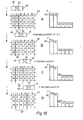
- FIGS. 10 and 11 again show image sections 59 from the image to be retouched during retouching and the associated color value profiles 60.
- a brush surface 48 consisting of three pixels 49 with a central correction zone 53 consisting of one pixel in different positions during the individual correction steps (KS) is indicated above the image sections 59.
- the color value F of the correction zone 53 is replaced by the mean value F o * formed from the color values of the three pixels.
- diagram (A) shows the unretouched image section 59 with a sharp contour 58, as can be seen from the entered color values and the color value profile 60.
- the retoucher guides the correction zone 53 of the brush surface 48 in several correction steps in the direction of the arrow over the image section 59 to be retouched and, after a correction step, displaces the brush surface or the correction zone 53 by one pixel perpendicular to the arrows.
- the color value changes achieved after the individual correction steps can be seen from the diagrams (B) to (D).
- the sharp contour 58 - diagram (A) - has been flattened onto an area 58 'which is three pixels wide. The area 58 'can be broadened further by additional correction steps to the left and right.
- the correction steps within the area 58' can be repeated any number of times in order to obtain a transition that is as linear as possible, as shown in FIG.
- FIG. 11, diagram (A), shows an image section 59 with a color value distribution which is identical to the color value distribution in FIG. 10, diagram (D).
- Diagrams (B) and (C) show the results after two repetitions of the correction steps (K.S.) carried out in FIG. 10, each repetition consisting of three correction steps. It can be seen from FIG. 11, diagram (C) that the color values have been linearized within the region 58 '.
- the second embodiment can of course also be used for smoothing noisy image areas, as was explained in FIG. 7.
- FIG. 12 shows an exemplary embodiment for the coordinate detection device 34 according to FIG. 1.
- the center points P of the brush surface 48 (FIG. 4) are marked with the coordinate pen 38 on the digitizing tablet 37, and the measuring stages 39 transmit the detected pixel coordinates x 0 and y 0 via a data bus 71, a comparison stage 72 and another Data bus 73 to an adder 74.
- the comparator 72 successive pairs of center coordinates x 0 and y 0 are continuously compared with one another.
- the comparison stage 72 supplies the "coordinate change" command on line 46 to an address counter 75.
- the address counter 75 started by the "coordinate change" command, calls all possible cyclically and line by line Coordinates of the X '/ Y' auxiliary coordinate system 52, which are fed to a computing stage 77 via a data bus 76.
- the computing stage 77 is programmed via a programming input 78 with the parameters of the desired brush surface 48 according to one of FIGS. 3a to 3c. Those called by the address counter 75. Coordinates are examined in the computing stage 77 to determine whether they fall into the brush surface 48. If this is the case, the coordinates called up are auxiliary coordinates x 'and y' of the brush surface 48.
- the auxiliary coordinates x 'and y l are passed via a data bus 79 to the adder stage 74, in which according to equation (1) the pixel coordinates x and y are formed.
- the pixel coordinates x and y reach the arithmetic circuit 36 and the address control unit 9 of the circuit arrangement according to FIG. 1 via the data bus 35.
- FIG. 13 shows an exemplary embodiment of the memory control unit 9 according to FIG. 1.
- the memory control unit 9 contains a clock generator 80, which counts a counting clock sequence T 0 via a counting input 81 into an X address counter 82.
- the X address counter 82 is a 9-bit binary counter and calls up the X addresses from 0 to 511 of the image repetition memories 7 and 8 via the address bus 10. After 511 counted cycles, a clock T 1 appears at the output of the X address counter 82 and is counted into a Y address counter 85 via a counter input 84.
- the Y address counter 85 is also a 9-bit binary counter and calls the corresponding Y addresses from 0 to 511 of the refresh memories 7 and 8 via the address bus 10.
- the Y address counter 85 also generates a clock T 2 at its output 86 after 511 counted clocks.
- the line start pulses (ZS) and the image start pulses (BS) on the lines 31 and 32 for the image recording are derived from the clock pulses T 1 and T 2 .
- the X address counter 82 and the Y address counter 85 are connected via the address bus 10 to the first comparison inputs 87 and 88 of comparators 89 and 90.
- the second comparison inputs 91 and 92 of the comparators 89 and 90 are acted upon with the pixel coordinates x and y, which are supplied by the coordinate computer 40 via the data bus 35.
- the signal outputs 93 and 94 of the comparators 89 and 90 are linked to one another via an AND gate 95. If the addresses are identical, the signal "light mark" appears on line 45, with which the movement of light mark 44 on screen 3 is synchronized with the movement of coordinate pin 38 of coordinate detection device 34.
- the invention is advantageously used in the entire field of electronic reproduction technology, in particular in the field of color image reproduction, by means of electronic color scanners and image processing systems for the production of retouched and corrected printing forms in the form of color separations or printing cylinders.
Landscapes
- Engineering & Computer Science (AREA)
- Multimedia (AREA)
- Signal Processing (AREA)
- Image Processing (AREA)
- Facsimile Image Signal Circuits (AREA)
- Color Image Communication Systems (AREA)
- Processing Of Color Television Signals (AREA)
Priority Applications (3)
| Application Number | Priority Date | Filing Date | Title |
|---|---|---|---|
| AT81101967T ATE17054T1 (de) | 1981-03-17 | 1981-03-17 | Verfahren zur partiell glaettenden retusche bei der elektronischen farbbildreproduktion. |
| DE8181101967T DE3173225D1 (en) | 1981-03-17 | 1981-03-17 | Method of partially smoothing a retouch during the electronic reproduction of colour images |
| EP81101967A EP0060312B1 (fr) | 1981-03-17 | 1981-03-17 | Procédé pour lisser une retouche partiellement lors de la reproduction électronique d'images en couleurs |
Applications Claiming Priority (1)
| Application Number | Priority Date | Filing Date | Title |
|---|---|---|---|
| EP81101967A EP0060312B1 (fr) | 1981-03-17 | 1981-03-17 | Procédé pour lisser une retouche partiellement lors de la reproduction électronique d'images en couleurs |
Publications (2)
| Publication Number | Publication Date |
|---|---|
| EP0060312A1 true EP0060312A1 (fr) | 1982-09-22 |
| EP0060312B1 EP0060312B1 (fr) | 1985-12-18 |
Family
ID=8187612
Family Applications (1)
| Application Number | Title | Priority Date | Filing Date |
|---|---|---|---|
| EP81101967A Expired EP0060312B1 (fr) | 1981-03-17 | 1981-03-17 | Procédé pour lisser une retouche partiellement lors de la reproduction électronique d'images en couleurs |
Country Status (3)
| Country | Link |
|---|---|
| EP (1) | EP0060312B1 (fr) |
| AT (1) | ATE17054T1 (fr) |
| DE (1) | DE3173225D1 (fr) |
Cited By (4)
| Publication number | Priority date | Publication date | Assignee | Title |
|---|---|---|---|---|
| EP0111026A1 (fr) * | 1982-12-11 | 1984-06-20 | DR.-ING. RUDOLF HELL GmbH | Procédé et appareil pour la retouche copiante dans la reproduction électronique d'images en couleurs |
| EP0269334A3 (en) * | 1986-11-14 | 1990-02-28 | Canon Kabushiki Kaisha | Color image processing apparatus |
| EP0359869A1 (fr) * | 1988-08-23 | 1990-03-28 | Agfa-Gevaert N.V. | Procédé de correction chromatique par le procédé de gravure sèche utilisant un cadre fabriqué photographiquement |
| WO1990007244A1 (fr) * | 1988-12-22 | 1990-06-28 | Rank Cintel Limited | Systeme de traitement d'images |
Citations (5)
| Publication number | Priority date | Publication date | Assignee | Title |
|---|---|---|---|---|
| DE2300515A1 (de) * | 1972-01-05 | 1973-07-19 | Crosfield Electronics Ltd | Scanner fuer reproduktionszwecke |
| FR2246897A1 (fr) * | 1973-10-01 | 1975-05-02 | Agency Ind Science Techn | |
| DE2607623A1 (de) * | 1976-02-25 | 1977-09-01 | Hell Rudolf Dr Ing Gmbh | Einrichtung zur herstellung von korrigierten farbauszuegen |
| EP0004078A2 (fr) * | 1978-03-10 | 1979-09-19 | DR.-ING. RUDOLF HELL GmbH | Procédé de correction de la couleur et circuit approprié |
| WO1980002607A1 (fr) * | 1979-05-18 | 1980-11-27 | Hell R Gmbh | Procede et dispositif de commutation par retouche electronique partielle lors de la reproduction d'images en couleurs |
-
1981
- 1981-03-17 EP EP81101967A patent/EP0060312B1/fr not_active Expired
- 1981-03-17 AT AT81101967T patent/ATE17054T1/de not_active IP Right Cessation
- 1981-03-17 DE DE8181101967T patent/DE3173225D1/de not_active Expired
Patent Citations (6)
| Publication number | Priority date | Publication date | Assignee | Title |
|---|---|---|---|---|
| DE2300515A1 (de) * | 1972-01-05 | 1973-07-19 | Crosfield Electronics Ltd | Scanner fuer reproduktionszwecke |
| FR2246897A1 (fr) * | 1973-10-01 | 1975-05-02 | Agency Ind Science Techn | |
| DE2446761A1 (de) * | 1973-10-01 | 1975-05-28 | Agency Ind Science Techn | Verfahren zur herstellung von farbauszuegen |
| DE2607623A1 (de) * | 1976-02-25 | 1977-09-01 | Hell Rudolf Dr Ing Gmbh | Einrichtung zur herstellung von korrigierten farbauszuegen |
| EP0004078A2 (fr) * | 1978-03-10 | 1979-09-19 | DR.-ING. RUDOLF HELL GmbH | Procédé de correction de la couleur et circuit approprié |
| WO1980002607A1 (fr) * | 1979-05-18 | 1980-11-27 | Hell R Gmbh | Procede et dispositif de commutation par retouche electronique partielle lors de la reproduction d'images en couleurs |
Cited By (4)
| Publication number | Priority date | Publication date | Assignee | Title |
|---|---|---|---|---|
| EP0111026A1 (fr) * | 1982-12-11 | 1984-06-20 | DR.-ING. RUDOLF HELL GmbH | Procédé et appareil pour la retouche copiante dans la reproduction électronique d'images en couleurs |
| EP0269334A3 (en) * | 1986-11-14 | 1990-02-28 | Canon Kabushiki Kaisha | Color image processing apparatus |
| EP0359869A1 (fr) * | 1988-08-23 | 1990-03-28 | Agfa-Gevaert N.V. | Procédé de correction chromatique par le procédé de gravure sèche utilisant un cadre fabriqué photographiquement |
| WO1990007244A1 (fr) * | 1988-12-22 | 1990-06-28 | Rank Cintel Limited | Systeme de traitement d'images |
Also Published As
| Publication number | Publication date |
|---|---|
| ATE17054T1 (de) | 1986-01-15 |
| DE3173225D1 (en) | 1986-01-30 |
| EP0060312B1 (fr) | 1985-12-18 |
Similar Documents
| Publication | Publication Date | Title |
|---|---|---|
| DE3110222C2 (de) | Verfahren zur partielle glättenden Retusche bei der elektronischen Farbbildreproduktion | |
| EP0111026B1 (fr) | Procédé et appareil pour la retouche copiante dans la reproduction électronique d'images en couleurs | |
| EP0029049B1 (fr) | Procede et dispositif de commutation par retouche electronique partielle lors de la reproduction d'images en couleurs | |
| DE2827596C2 (de) | Verfahren und Anordnung zur Herstellung gerasterter Druckformen | |
| DE2853509C2 (de) | Einrichtung zur Herstellung von Farbauszügen | |
| DE3543262C2 (fr) | ||
| DE19724066B4 (de) | Verfahren zur Korrektur von Geometriefehlern bei der Übertragung von Informationen auf einen Bedruckstoff | |
| EP0059705B1 (fr) | Procede et circuit pour la correction partielle du dessin lors de la reproduction d'images en couleur | |
| DE3233427A1 (de) | Verfahren zum aendern der farbwiedergabe in dem auf einer farbbildroehre wiedergegebenen bild einer vorlage zur verwendung beim mehrfarbendruck | |
| WO1985001408A1 (fr) | Dispositif de controle d'image en couleurs pour un moniteur couleur | |
| EP0187837B1 (fr) | Procede de fabrication de cylindres d'impression pour un dessin sans joint, respectivement sans fin au moyen de machines a graver a matrice a emboutir | |
| EP0986465A1 (fr) | Procede de gravure de cylindres d'impression | |
| DE4341536C2 (de) | Bildverarbeitungseinrichtung | |
| DE2621008B2 (de) | Verfahren zur Gewinnung und Verwertung von Farbkorrekturdaten für die Farbbildaufzeichnung | |
| EP0060312B1 (fr) | Procédé pour lisser une retouche partiellement lors de la reproduction électronique d'images en couleurs | |
| EP0060243A1 (fr) | Procede et circuit pour la correction electronique partielle lors de la reproduction d'images en couleur. | |
| WO2000077725A1 (fr) | Procede et dispositif pour la synchronisation lors du codage et du decodage de donnees imprimees en bande | |
| DE3110517C2 (de) | Verfahren und Schaltungsanordnung zur partiellen elektronischen Korrektur der Strukturierung bei der Farbbildreproduktion | |
| DE4108253C2 (de) | Verfahren und Anordnung zur Herstellung von gerasterten Farbauszügen und Druckformen | |
| DE4105263C2 (de) | Bildverarbeitungseinrichtung | |
| DE4423982C2 (de) | Automatische Erzeugung eines periodischen Musters ohne Auftreten von MoirE | |
| DE3734686A1 (de) | Verfahren zur bildung von halbtonpunkten | |
| DE4124828A1 (de) | Verfahren zum ausgeben eines grautonbildes als pseudo-halbtonbild sowie anordnung zur durchfuehrung des verfahrens | |
| EP4169720A1 (fr) | Procédé d'inspection d'image d'impression dans un procédé d'impression numérique | |
| DE10055030B4 (de) | Verfahren zum Vermessen von gravierten Näpfchen |
Legal Events
| Date | Code | Title | Description |
|---|---|---|---|
| PUAI | Public reference made under article 153(3) epc to a published international application that has entered the european phase |
Free format text: ORIGINAL CODE: 0009012 |
|
| 17P | Request for examination filed |
Effective date: 19820406 |
|
| AK | Designated contracting states |
Designated state(s): AT BE CH DE FR GB IT NL SE |
|
| GRAA | (expected) grant |
Free format text: ORIGINAL CODE: 0009210 |
|
| AK | Designated contracting states |
Designated state(s): AT BE CH DE FR GB IT LI NL SE |
|
| REF | Corresponds to: |
Ref document number: 17054 Country of ref document: AT Date of ref document: 19860115 Kind code of ref document: T |
|
| REF | Corresponds to: |
Ref document number: 3173225 Country of ref document: DE Date of ref document: 19860130 |
|
| ITF | It: translation for a ep patent filed |
Owner name: FIAMMENGHI - DOMENIGHETTI |
|
| ET | Fr: translation filed | ||
| PLBE | No opposition filed within time limit |
Free format text: ORIGINAL CODE: 0009261 |
|
| STAA | Information on the status of an ep patent application or granted ep patent |
Free format text: STATUS: NO OPPOSITION FILED WITHIN TIME LIMIT |
|
| 26N | No opposition filed | ||
| PG25 | Lapsed in a contracting state [announced via postgrant information from national office to epo] |
Ref country code: DE Effective date: 19871201 |
|
| PGFP | Annual fee paid to national office [announced via postgrant information from national office to epo] |
Ref country code: CH Payment date: 19920219 Year of fee payment: 12 |
|
| PGFP | Annual fee paid to national office [announced via postgrant information from national office to epo] |
Ref country code: BE Payment date: 19920220 Year of fee payment: 12 Ref country code: AT Payment date: 19920220 Year of fee payment: 12 |
|
| PGFP | Annual fee paid to national office [announced via postgrant information from national office to epo] |
Ref country code: GB Payment date: 19920312 Year of fee payment: 12 |
|
| PGFP | Annual fee paid to national office [announced via postgrant information from national office to epo] |
Ref country code: SE Payment date: 19920316 Year of fee payment: 12 |
|
| PGFP | Annual fee paid to national office [announced via postgrant information from national office to epo] |
Ref country code: FR Payment date: 19920330 Year of fee payment: 12 |
|
| ITTA | It: last paid annual fee | ||
| PGFP | Annual fee paid to national office [announced via postgrant information from national office to epo] |
Ref country code: NL Payment date: 19920331 Year of fee payment: 12 |
|
| REG | Reference to a national code |
Ref country code: FR Ref legal event code: TP Ref country code: FR Ref legal event code: CA |
|
| BECN | Be: change of holder's name |
Effective date: 19920422 |
|
| PG25 | Lapsed in a contracting state [announced via postgrant information from national office to epo] |
Ref country code: GB Effective date: 19930317 Ref country code: AT Effective date: 19930317 |
|
| PG25 | Lapsed in a contracting state [announced via postgrant information from national office to epo] |
Ref country code: SE Effective date: 19930318 |
|
| PG25 | Lapsed in a contracting state [announced via postgrant information from national office to epo] |
Ref country code: LI Effective date: 19930331 Ref country code: CH Effective date: 19930331 Ref country code: BE Effective date: 19930331 |
|
| BERE | Be: lapsed |
Owner name: LINOTYPE-HELL A.G. Effective date: 19930331 |
|
| PG25 | Lapsed in a contracting state [announced via postgrant information from national office to epo] |
Ref country code: NL Effective date: 19931001 |
|
| NLV4 | Nl: lapsed or anulled due to non-payment of the annual fee | ||
| GBPC | Gb: european patent ceased through non-payment of renewal fee |
Effective date: 19930317 |
|
| PG25 | Lapsed in a contracting state [announced via postgrant information from national office to epo] |
Ref country code: FR Effective date: 19931130 |
|
| REG | Reference to a national code |
Ref country code: CH Ref legal event code: PL |
|
| REG | Reference to a national code |
Ref country code: FR Ref legal event code: ST |
|
| EUG | Se: european patent has lapsed |
Ref document number: 81101967.8 Effective date: 19931008 |