EP0059639A2 - Verfahren zum elektroerosiven Drahtschneiden - Google Patents
Verfahren zum elektroerosiven Drahtschneiden Download PDFInfo
- Publication number
- EP0059639A2 EP0059639A2 EP82301041A EP82301041A EP0059639A2 EP 0059639 A2 EP0059639 A2 EP 0059639A2 EP 82301041 A EP82301041 A EP 82301041A EP 82301041 A EP82301041 A EP 82301041A EP 0059639 A2 EP0059639 A2 EP 0059639A2
- Authority
- EP
- European Patent Office
- Prior art keywords
- machining
- electric discharge
- closed loop
- work
- discharge machining
- Prior art date
- Legal status (The legal status is an assumption and is not a legal conclusion. Google has not performed a legal analysis and makes no representation as to the accuracy of the status listed.)
- Granted
Links
Images

Classifications
-
- B—PERFORMING OPERATIONS; TRANSPORTING
- B23—MACHINE TOOLS; METAL-WORKING NOT OTHERWISE PROVIDED FOR
- B23H—WORKING OF METAL BY THE ACTION OF A HIGH CONCENTRATION OF ELECTRIC CURRENT ON A WORKPIECE USING AN ELECTRODE WHICH TAKES THE PLACE OF A TOOL; SUCH WORKING COMBINED WITH OTHER FORMS OF WORKING OF METAL
- B23H7/00—Processes or apparatus applicable to both electrical discharge machining and electrochemical machining
- B23H7/02—Wire-cutting
- B23H7/06—Control of the travel curve of the relative movement between electrode and workpiece
Definitions
- the present invention relates to a wire-cut, electric and machine discharge machining method/for cutting a work into one or more closed loop configurations as of a punch, die or the like through the use of a wire-cut, electric discharge machine is provided with an automatic wire feed mechanism.
- the invention / applicable particularly, but not exclusively,/ to such a wire-cut, and machine electric discharge machining method/which permits further machining even in the case of a wire electrode being broken during machining, and which makes the machining operation less troublesome.
- Fig. 1 is explanatory of a conventional wire-cut, electric discharge machining method for cutting out a punch from a work by the employment of a wire-cut, electric discharge machine provided with an automatic wire feed mechanism.
- reference numeral 1 indicates a work; 2 designates a machining start hole; 3 identifies a part left uncut; 4 denotes a punched portion; and 5 represents adhesive materials.
- a wire electrode (not shown) is first inserted into the machining start hole 2 made in the work 1, and electric discharge machining is performed along a route (A ⁇ B + C) and is stopped at the point C, leaving the part 3 uncut.
- the reason for leaving the part 3 uncut is to prevent the punched portion 4 from falling off the work 1, avoiding breakage of the wire electrode.
- the punched portion 4 is fixed to the work 1 using the adhesive binder as indicated by 5 in Fig. 1 and then electric discharge machining is carried out along the broken-line route (C + B) to cut off the part remaining uncut 3, obtaining a punch.
- the wire electrode and the work 1 are moved relative to each other to the same positions as they were placed at the start of the machining operation and the wire electrode is inserted by the automatic wire feed mechanism into the machining start hole 2 for reinstallment on the running system.
- the wire electrode and the work 1 are moved relative to each other along the machining route where the electric discharge machining operation has already been conducted. After the wire electrode and the work 1 have thus been brought to the same relative positions as those when the wire electrode was broken, the electric discharge machining operation is started again.
- the machining operation can be automatically resumed by the abovesaid method, but in the case of breakage of the wire electrode during machining along the route (C + B), no further machining can be carried out. That is to say, since the punched portion 4 is fixed to the work 1 as indicated by 5 in Fig. 1 before the machining operation along the route (C + B), the presence of the fixed portions 5 makes it impossible to move the wire electrode and the work 1 relative to each other along the machining route where the electric discharge machining has already been effected.
- Fig. 2 is explanatory of cutting a work into a plurality of punches by the conventional wire-cut, electric discharge machining method using the wire-cut, electric discharge machine provided with the automatic wire feed mechanism.
- reference numeral 6 indicates a work; 7, 9 and 11 designate machining start holes; 8, 10 and 12 identify parts remaining uncut; 13 to 15 denote punched portions; and, 16a. to 16f represent adhesive materials.
- a wire electrode (not shown) is inserted into the machining start hole 7 and electric discharge machining is performed along the route (A + B ⁇ C) and, at the point C, the machining operation is stopped, leaving the part 8 uncut.
- the punched portion 13 is fixed to the work 6 using the adhesive material as indicated by 16a and 16b and then electric discharge machining is carried out along the broken-line route (C ⁇ B), thus cutting out the punched portion 13 from the work 6.
- the wire electrode is inserted by the automatic wire feed mechanism into the machining start hole 9 and, as described above, electric discharge machining is effected along the route (D ⁇ E ⁇ F); the part 10 is left uncut; the punched portion 14 is fixed to the work 6 using the adhesive material as indicated by 16c and 16d; and then electric discharge machining takes place along the broken-line route (F ⁇ E), cutting out the punched portion 14 from the work 6.
- the punched portion 15 is also cut out in the same manner as described above.
- the punched portions are cut out from the work 6 one by one; hence, this method is very troublesome in that the punched portions 13 to 15 have to be fixed to the work 6 after electric discharge machining along the routes (A ⁇ B ⁇ C), (D ⁇ E - F) and (G ⁇ H ⁇ I), respectively, Moreover, if the wire electrode is broken during cutting off the parts left uncut 8, 10 and 12, no further machining can be effected as described previously.
- a wire-cut, electric discharge machining method for cutting from a work a cut-away portion defined by a closed loop machining path by means of a wire-cut, electric discharge machine provided with an automatic wire feed mechanism for automatically installing a wire electrode on a wire electrode running system, the method comprising the steps of:
- the wire electrode is subsequently re inserted by the automatic wire feed mechanism into the machining start hole of the closed loop and is moved to the position of its breakage along the route and in the direction in which the electric discharge machining operation was being carried out immediately prior to the breakage, and then the electrid discharge operation is resumed.
- the method may be adapted for cutting from a work a plurality of cut-away portions defined by respective closed loop machining paths, wherein in one machining - stage the closed loop paths are machined one after another to said points of suspension of said electric discharge machining operations where a part of each closed loop configuration is left uncut;
- a wire-cut, electric discharge machine provided with an automatic wire feed mechanism for automatically installing a wire electrode on a wire electrode running system, the machine being adapted and arranged to perform a machining method for cutting from a work a cut-way portion defined by a closed loop machining path, the method comprising the steps of:
- the machine may be adapted for cutting from a work a plurality of cut-away portions defined by respective closed loop machining paths, wherein in one machining stage the closed loop paths are machined one after another to said points of suspension of said electric discharge machining operations where a part of each closed loop configuration is left uncut;
- Preferred examples of the present invention may provide a wire-cut, electric discharge machining method and machine which permit automatic resumption of wire-cut, electric discharge machining even if the wire electrode is broken during electric discharge machining.
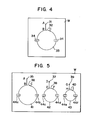
- Fig. 4 is explanatory of a machining method of the present invention, illustrating the case of cutting out a punch from the work W.
- reference numeral 31 indicates a machining start hole; 32 designates a part remaining uncut; 33 identifies a punched portion; and 34 denotes adhesive materials.
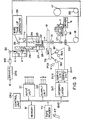
- the machining operation starts with passing the wire electrode P through the machining start hole 31 made in the work W, then installing the wire electrode P on the running system as shown in Fig. 3, followed by reading out the command tape PT by the tape reader TR to start machining.
- the control unit CPU sequentially reads out a machining route (A ⁇ B + C) stored on the command tape PT, performs wire diameter compensation and other necessary processing and then applies the results of the processing to the interpolater INT.
- the interpolater INT responding to the information from the control unit CPU, conducts pulse distribution, providing output pulse signals to the servo units SVX and SVY.
- the motors MX and MY are driven to feed the table TB with the work W mounted thereon, performing electric discharge machining along the route (A + B + C).
- the punched portion 33 is fixed by the operator to the work W using the adhesive binder as indicated by 34 in Fig. 4.
- control unit CPU applies a control signal f, produced based on a command stored on the command tape PT, to the cutter driver CTD via the output unit DO to activate the cutter CT, cutting off the wire electrode P.
- control unit CPU supplies the interpolater INT with information on the distance of movement of the table TB for alignment of the top end portion of the nozzle 21 with the machining start hole 31.
- the motors MX and MY are driven to move the table TB as required.
- the control unit CPU detects the current position of the table TB on the basis of signals a and b which are applied via the input unit DI from the position detectors PCX and PCY.
- the control unit CPU Having detected the alignment of the open end portion of the nozzle 21 with the machining start hole 31, the control unit CPU provides a control signal g via the output unit DO to the driver DR2, operating the motor M2.
- the reel 30 is driven to let out a cord retained at one end to the reel 30 and at the other end to the slide member 27, permitting the slide member 27 and the wire gripper 22 fixed thereto to go down along the groove 29 cut in the shaft 28, as indicated by the broken-line arrow.
- the wire gripper 22 has reached the upper surface of the work W, the abovesaid cord becomes loose to turn OFF the limit switch L2 and its output signal d becomes "0".
- the control unit CPU stops the motor M2 from operation and, at the same time, applies a control signal h via the output unit DO to the driver DR1 to drive the motor Ml, thereby activating the wire feed mechanism 20 to feed thewire electrode P upwardly.
- the wire feed mechanism 20 is so arranged as to grip the wire electrode P only when the motor M1 is in operation.
- the control unit CPU stops the motor M1.
- the wire gripper 22 is to grip the wire electrode P fed thereto through the nozzle 21 and the machining start hole 31.
- control unit CPU provides the control signal g via the output unit DO to the driver DR2 to drive the motor M 2 in the reverse direction, by which the slide member 27 and the wire gripper 22 move up along the groove 29 as indicated by the broken-line arrow.
- the limit switch L3 is turned ON and its output signal e becomes "1".
- the control unit CPU applies the control signal g via the output unit DO to the driver DR2 to stop the motor M2.
- the control unit CPU supplies the control signal g to the driver DR2, returning the wire gripper 22 and the slide member 27 to the illustrated positions.
- the control unit CPU sequentially reads out the machining route (A -+ B) stored on the command tape PT, performs arithmetic processing and applies the result of the processing to the interpolater INT to operate the motors MX . and MY so that the wire electrode P is brought to the point B where wire-cut, electric discharge machining starts.
- the control unit CPU sequentially reads out a program of the broken-line route (B + C) stored on the command tape PT, carries out wire diameter compensation and other necessary processing, applies the result s of the processing to the interpolater INT and, at the same time, provides a control signal to a power source unit (not shown), resuming the electric discharge machining operation.
- the table TB having mounted theron the work W is fed to conduct electric discharge machining along the route (B + C), cutting out the punched portion 33 from the work W.
- the limit switch L1 Upon breakage of the wire electrode P in the course of electric discharge machining, the limit switch L1 is turned OFF and its output signal c becomes "0".
- the control unit CPU decides that the wire electrode P has been broken, and stores information on the current position of the table TB in the memory M and, further, provides a control signal to the interpolater INT, stopping the motors MX and MY. Then the distance of movement of the table TB, which is necessary for alignment of the open end portion of the nozzle'21 with the machining start hole 31, is obtained from the information on the current position of the table TB and the information on the position of the machining start hole 31, both stored in the memory M.
- the control unit CPU applies the control signals h and g to the drivers DR1 and DR2, respectively, reinstalling the wire electrode P on the running system in a similar manner as described previously.
- control unit CPU performs either one of the following two control operations depending upon whether the breakage of the wire electrode P has been detected during the electric discharge machining along the solid-line route (A ⁇ B ⁇ C) or the broken-line route (B ⁇ C).
- the wire electrode P is passed through the machining start hole 31, the table TB is fed so that the wire electrode P may move along the route where the electric discharge machining has already been completed, and the electric discharge machining is started again when the wire electrode P has reached the position where it was broken.
- the wire electrode P is passed through the machining start hole 31, the table TB is fed in a manner to move the wire electrode P along the route (A + B) and then the table TB is further fed to move the wire electrode P along the broken-line route (B ⁇ C) to the position where it was broken. Thereafter the electric discharge machining is resumed.
- Fig. 5 is explanatory of the operation for cutting out a plurality of punches from the work W according to this invention method.
- reference numerals 35, 37 and 39 indicate machining start holes; 36, 38 and 40 designate parts remaining uncut; 41 to 43 identify punched portions; and 44a to 44f denote fixed parts.
- the wire-cut, electric discharge machine shown in Fig. 3 is employed.
- the wire electrode P is passed through the machining start hole 35, electric discharge machining is carried out along the solid-line route (A ⁇ B * C) and, at the point C, the electric discharge machining is stopped leaving the portion 36 uncut.
- the control unit CPU controls the cutter CT and the motors Ml, M2, MX and MY to pass the wire electrode P through the machining start hole 37 and perform electric discharge machining along the solid-line route (D + F ⁇ F), leaving the portion 38 uncut.
- the control unit CPU controls the respective parts to pass the wire electrode P through the machining start hole 39 and perform electric discharge machining along the solid-line route (G ⁇ H + I), leaving the portion 40 uncut.
- the control unit CPU stops the electric discharge machining.
- the operator fixes the punched portions 41 to 43 to the work W using the adhesive binder as indicated by 44a to 44f. By fixing all the punched portions 41 to 43 to the work W at one time in this way, the operation can be made less troublesome.
- the operator After fixing the punched portions 41 to 43 to the work W, the operator enters a machining restart command to the control unit CPU via the input unit DI, for instance.
- the control unit CPU controls the cutter CT and the motors M1 , M2, MX and MY to pass the wire electrode P through the machining start hole 35 and feed the table TB so that the electrode P may move along the route (A ⁇ B).
- electric discharge machining takes place along the broken-line route (B ⁇ C) to cut off the part left uncut 36, cutting out the punched portion 41.
- the punched portions 42 and 43 are cut out in the same manner as in the case of cutting out the punched portion 41.
- the wire electrode P In the event that the wire electrode P has been broken during electric discharge machining along the solid-line route (A ⁇ B ⁇ C), (D ⁇ E + F) or (G ⁇ H ⁇ I), the wire electrode P is passed through the machining start hole 35, 37 or 39 and the table TB is fed so that the wire electrode P may move to the position of its breakage along the machining route where the electric discharge has already been effected, thereafter resuming the electric discharge machining operation.
- the wire electrode P When the wire electrode P has been broken while in the electric discharge machining operation along the broken-line route (B ⁇ C), (E ⁇ F) or (H ⁇ I) for cutting off the part left uncut 36, 38 or 40, the wire electrode P is passed through the machining start hole 35, 37 or 39 and the table TB is fed so that the wire electrode P may move along the route (A ⁇ B), (D + E) or (G ⁇ H) and then the table TB is further fed so that the wire electrode P may move along the broken-line route (B ⁇ C), Consequently ( E ⁇ F) or (H ⁇ I) to the position where it was broken. even if the wire electrode P is broken while cutting off the part left uncut 36, 38, or 40, further machining can be performed as described previously.
- the wire electrode when broken, is passed through the machining start hole by means of the automatic wire feed mechanism and is moved to the position of its breakage along the machining route where electric discharge machining has already been carried out immediately before breakage and then the electric discharge machining operation is restarted; therefore, even if the wire electrode is broken in the course of cutting off the part left uncut, the machining operation can automatically be resumed.
- the parts remaining uncut are formed for all of the closed loop configurations one after another, and then the closed loop configurations are all fixed to the work at one time; accordingly, the machining operation can be simplified.
- closed loop machining patht is shown as circular.
- the closed loop machining paths could be square, triangular, or any other desired shape. Also, they could have different shapes.
Landscapes
- Chemical & Material Sciences (AREA)
- Chemical Kinetics & Catalysis (AREA)
- Electrochemistry (AREA)
- Engineering & Computer Science (AREA)
- Mechanical Engineering (AREA)
- Electrical Discharge Machining, Electrochemical Machining, And Combined Machining (AREA)
Applications Claiming Priority (2)
| Application Number | Priority Date | Filing Date | Title |
|---|---|---|---|
| JP56029731A JPS57144629A (en) | 1981-03-02 | 1981-03-02 | Wire cut discharge working method |
| JP29731/81 | 1981-03-02 |
Publications (3)
| Publication Number | Publication Date |
|---|---|
| EP0059639A2 true EP0059639A2 (de) | 1982-09-08 |
| EP0059639A3 EP0059639A3 (en) | 1984-05-02 |
| EP0059639B1 EP0059639B1 (de) | 1986-09-10 |
Family
ID=12284242
Family Applications (1)
| Application Number | Title | Priority Date | Filing Date |
|---|---|---|---|
| EP82301041A Expired EP0059639B1 (de) | 1981-03-02 | 1982-03-02 | Verfahren zum elektroerosiven Drahtschneiden |
Country Status (4)
| Country | Link |
|---|---|
| US (1) | US4544819A (de) |
| EP (1) | EP0059639B1 (de) |
| JP (1) | JPS57144629A (de) |
| DE (1) | DE3273092D1 (de) |
Cited By (6)
| Publication number | Priority date | Publication date | Assignee | Title |
|---|---|---|---|---|
| DE3902173A1 (de) * | 1988-01-25 | 1989-08-03 | Mitsubishi Electric Corp | Elektroentladungsmaschine mit drahtelektrode |
| DE3909252A1 (de) * | 1988-03-22 | 1989-10-05 | Mitsubishi Electric Corp | Verfahren zur elektrischen schneiddraht-entladungsbearbeitung |
| EP0512314A3 (en) * | 1991-05-03 | 1992-12-23 | Ag Fuer Industrielle Elektronik Agie Losone Bei Locarno | Method of electric discharge cutting and wire cutting machine for carrying out the invention |
| EP0503509A3 (en) * | 1991-03-08 | 1993-01-27 | Martin Gaese | Electro-erosion wire cutting method |
| DE4131650A1 (de) * | 1991-09-23 | 1993-03-25 | Agie Ag Ind Elektronik | Verfahren zur funkenerosiven bearbeitung von werkstuecken mittels eines drahtes |
| KR101137648B1 (ko) * | 2011-09-07 | 2012-04-19 | 박환진 | 합성수지관 연결장치 |
Families Citing this family (17)
| Publication number | Priority date | Publication date | Assignee | Title |
|---|---|---|---|---|
| CH659415A5 (de) * | 1983-06-09 | 1987-01-30 | Agie Ag Ind Elektronik | Verfahren zur sicherung ausgeschnittener stuecke beim funkenerosiven schneiden sowie anwendung des verfahrens. |
| CH656082A5 (fr) * | 1984-04-18 | 1986-06-13 | Charmilles Technologies | Machine pour decoupage par electroerosion avec immobilisation de la chute. |
| CH659605A5 (fr) * | 1984-09-11 | 1987-02-13 | Charmilles Technologies | Machine d'electroerosion pour l'etincelage par fil et pour l'enfoncage. |
| CH673970A5 (de) * | 1986-10-30 | 1990-04-30 | Charmilles Technologies | |
| JPH01140924A (ja) * | 1987-11-26 | 1989-06-02 | Fanuc Ltd | 自動ワイヤ結線方法 |
| JPH01205929A (ja) * | 1988-02-15 | 1989-08-18 | Fanuc Ltd | Ncデータ作成方法 |
| JPH0673776B2 (ja) * | 1988-03-01 | 1994-09-21 | 三菱電機株式会社 | ワイヤ放電加工装置の断線復帰制御方法 |
| KR930011213B1 (ko) * | 1989-08-25 | 1993-11-29 | 미쯔비시덴끼 가부시끼가이샤 | 와이어 방전가공 방법 및 그 장치 |
| NL9100549A (nl) * | 1990-03-27 | 1991-10-16 | Seafloor Engineers Inc | Onafhankelijk apparaat en dito werkwijze voor het bepalen van de statische en dynamische belastingskarakteristieken van een grondlaag. |
| US5127261A (en) * | 1990-03-27 | 1992-07-07 | Fugro-Mcclelland Leasing, Inc. | Self-contained apparatus and method for determining the static and dynamic loading characteristics of a soil bed |
| DE4116868C2 (de) * | 1991-05-23 | 1995-07-27 | Agie Ag Ind Elektronik | Verfahren zur Bearbeitung von Werkstücken, insbesondere zur funkenerosiven Bearbeitung von Werkstücken mittels eines Drahtes |
| JPH0819918A (ja) * | 1994-07-07 | 1996-01-23 | Mitsubishi Electric Corp | ワイヤ放電加工方法及びその装置 |
| JP3366509B2 (ja) * | 1995-08-23 | 2003-01-14 | ファナック株式会社 | ワイヤ放電加工方法 |
| US8338736B2 (en) * | 2008-08-21 | 2012-12-25 | General Electric Company | Extraction of chordal test specimens from forgings |
| US9878385B2 (en) * | 2013-12-19 | 2018-01-30 | Mitsubishi Electric Corporation | Wire electric discharge machining apparatus, wire electric discharge machining method, and control device |
| CN105939807B (zh) * | 2013-12-19 | 2017-08-18 | 三菱电机株式会社 | 线放电加工装置、线放电加工方法及控制装置 |
| JP6219785B2 (ja) * | 2014-06-23 | 2017-10-25 | ファナック株式会社 | 断線修復手段を備えたワイヤ放電加工機 |
Family Cites Families (4)
| Publication number | Priority date | Publication date | Assignee | Title |
|---|---|---|---|---|
| DE2755724C2 (de) * | 1977-12-14 | 1983-06-16 | Siemens AG, 1000 Berlin und 8000 München | Vorrichtung für die Unterstützung der Schnittstelle und des auszuschneidenden Kernes beim Drahterodieren |
| JPS55137835A (en) * | 1979-04-09 | 1980-10-28 | Mitsubishi Electric Corp | Method of electrical working |
| CH629411A5 (fr) * | 1979-06-21 | 1982-04-30 | Charmilles Sa Ateliers | Machine a usiner par etincelage erosif. |
| JPS5627741A (en) * | 1979-08-03 | 1981-03-18 | Fanuc Ltd | Processing method of wire electrode disconnection |
-
1981
- 1981-03-02 JP JP56029731A patent/JPS57144629A/ja active Pending
-
1982
- 1982-03-02 EP EP82301041A patent/EP0059639B1/de not_active Expired
- 1982-03-02 DE DE8282301041T patent/DE3273092D1/de not_active Expired
-
1984
- 1984-06-27 US US06/624,806 patent/US4544819A/en not_active Expired - Fee Related
Cited By (8)
| Publication number | Priority date | Publication date | Assignee | Title |
|---|---|---|---|---|
| DE3902173A1 (de) * | 1988-01-25 | 1989-08-03 | Mitsubishi Electric Corp | Elektroentladungsmaschine mit drahtelektrode |
| US5043550A (en) * | 1988-01-25 | 1991-08-27 | Mitsubishi Denki K.K. | Wire cut electric discharge machine |
| DE3909252A1 (de) * | 1988-03-22 | 1989-10-05 | Mitsubishi Electric Corp | Verfahren zur elektrischen schneiddraht-entladungsbearbeitung |
| EP0503509A3 (en) * | 1991-03-08 | 1993-01-27 | Martin Gaese | Electro-erosion wire cutting method |
| EP0512314A3 (en) * | 1991-05-03 | 1992-12-23 | Ag Fuer Industrielle Elektronik Agie Losone Bei Locarno | Method of electric discharge cutting and wire cutting machine for carrying out the invention |
| US5386093A (en) * | 1991-05-03 | 1995-01-31 | Agie, A.G. Fur Industrielle Elektronik | Method for electroerosive cutting and wire EDM machine |
| DE4131650A1 (de) * | 1991-09-23 | 1993-03-25 | Agie Ag Ind Elektronik | Verfahren zur funkenerosiven bearbeitung von werkstuecken mittels eines drahtes |
| KR101137648B1 (ko) * | 2011-09-07 | 2012-04-19 | 박환진 | 합성수지관 연결장치 |
Also Published As
| Publication number | Publication date |
|---|---|
| US4544819A (en) | 1985-10-01 |
| DE3273092D1 (en) | 1986-10-16 |
| EP0059639A3 (en) | 1984-05-02 |
| JPS57144629A (en) | 1982-09-07 |
| EP0059639B1 (de) | 1986-09-10 |
Similar Documents
| Publication | Publication Date | Title |
|---|---|---|
| EP0059639B1 (de) | Verfahren zum elektroerosiven Drahtschneiden | |
| EP0023824A1 (de) | Verfahren für die Wiederherstellung einer gebrochenen Drahtelektrode | |
| JPH0957539A (ja) | ワイヤ放電加工方法 | |
| US4816636A (en) | Wire cut electric discharge machine | |
| EP0286684A1 (de) | Drahtschneidefunkenerosionsmaschine | |
| EP3520944A1 (de) | Drahterodiermaschine und verfahren zur steuerung der drahterodiermaschine | |
| EP0062078A1 (de) | Vorrichtung zum abkuppeln einer drahtelektrode | |
| US4940871A (en) | Method of restoring a wire electrode broken during an electric discharge machining operation | |
| US4891487A (en) | Electrode return control for electric spark machine | |
| EP0356520B1 (de) | Selbsttätiges drahtverbindungssystem | |
| JPH0238330B2 (de) | ||
| EP0413889B1 (de) | Verfahren und Apparat zur Elektroentladungsbearbeitung mit Drahtelektrode | |
| JP3773318B2 (ja) | ワイヤ放電加工機 | |
| EP0663258B1 (de) | Verfahren zum Erfassen von anormalen Betriebszuständen während des automatischen Drahtvorschubs auf eine Funkenerosionsmaschine | |
| US5563797A (en) | Wire-cut discharge machine having a display for guiding returning of workpiece to machining start position | |
| JPS58196926A (ja) | ワイヤカツト放電加工装置のワイヤ電極供給装置 | |
| JPS5969220A (ja) | 放電加工機の電極ジヤンプ制御方式 | |
| JPH10328938A (ja) | ワイヤ放電加工方法及び装置 | |
| JPS6211970B2 (de) | ||
| JPH03117519A (ja) | ワイヤ放電加工方法 | |
| JPH0360925A (ja) | ワイヤ放電加工装置 | |
| JP2575710B2 (ja) | ワイヤカット放電加工装置 | |
| JPH05301119A (ja) | ワイヤカット放電加工機 | |
| JPS6339734A (ja) | ワイヤ放電加工装置 | |
| US5043551A (en) | Wire cut-type electric discharging method |
Legal Events
| Date | Code | Title | Description |
|---|---|---|---|
| PUAI | Public reference made under article 153(3) epc to a published international application that has entered the european phase |
Free format text: ORIGINAL CODE: 0009012 |
|
| AK | Designated contracting states |
Designated state(s): CH DE FR GB LI |
|
| RAP1 | Party data changed (applicant data changed or rights of an application transferred) |
Owner name: FANUC LIMITED |
|
| PUAL | Search report despatched |
Free format text: ORIGINAL CODE: 0009013 |
|
| AK | Designated contracting states |
Designated state(s): CH DE FR GB LI |
|
| 17P | Request for examination filed |
Effective date: 19840413 |
|
| GRAA | (expected) grant |
Free format text: ORIGINAL CODE: 0009210 |
|
| AK | Designated contracting states |
Kind code of ref document: B1 Designated state(s): CH DE FR GB LI |
|
| REF | Corresponds to: |
Ref document number: 3273092 Country of ref document: DE Date of ref document: 19861016 |
|
| ET | Fr: translation filed | ||
| PLBE | No opposition filed within time limit |
Free format text: ORIGINAL CODE: 0009261 |
|
| STAA | Information on the status of an ep patent application or granted ep patent |
Free format text: STATUS: NO OPPOSITION FILED WITHIN TIME LIMIT |
|
| 26N | No opposition filed | ||
| PGFP | Annual fee paid to national office [announced via postgrant information from national office to epo] |
Ref country code: DE Payment date: 19910211 Year of fee payment: 10 |
|
| PGFP | Annual fee paid to national office [announced via postgrant information from national office to epo] |
Ref country code: FR Payment date: 19910212 Year of fee payment: 10 |
|
| PGFP | Annual fee paid to national office [announced via postgrant information from national office to epo] |
Ref country code: GB Payment date: 19910219 Year of fee payment: 10 |
|
| PGFP | Annual fee paid to national office [announced via postgrant information from national office to epo] |
Ref country code: CH Payment date: 19910628 Year of fee payment: 10 |
|
| PG25 | Lapsed in a contracting state [announced via postgrant information from national office to epo] |
Ref country code: GB Effective date: 19920302 |
|
| PG25 | Lapsed in a contracting state [announced via postgrant information from national office to epo] |
Ref country code: LI Effective date: 19920331 Ref country code: CH Effective date: 19920331 |
|
| GBPC | Gb: european patent ceased through non-payment of renewal fee | ||
| PG25 | Lapsed in a contracting state [announced via postgrant information from national office to epo] |
Ref country code: FR Effective date: 19921130 |
|
| REG | Reference to a national code |
Ref country code: CH Ref legal event code: PL |
|
| PG25 | Lapsed in a contracting state [announced via postgrant information from national office to epo] |
Ref country code: DE Effective date: 19921201 |
|
| REG | Reference to a national code |
Ref country code: FR Ref legal event code: ST |