EP0059303B1 - Anordnung zum Kühlen des Kraftstoffs in einem Betriebssystem eines Dieselmotors mit einem geschlossenen Einspritzkreislauf - Google Patents
Anordnung zum Kühlen des Kraftstoffs in einem Betriebssystem eines Dieselmotors mit einem geschlossenen Einspritzkreislauf Download PDFInfo
- Publication number
- EP0059303B1 EP0059303B1 EP82100183A EP82100183A EP0059303B1 EP 0059303 B1 EP0059303 B1 EP 0059303B1 EP 82100183 A EP82100183 A EP 82100183A EP 82100183 A EP82100183 A EP 82100183A EP 0059303 B1 EP0059303 B1 EP 0059303B1
- Authority
- EP
- European Patent Office
- Prior art keywords
- fuel
- cooling
- circuit
- fuel tank
- injection circuit
- Prior art date
- Legal status (The legal status is an assumption and is not a legal conclusion. Google has not performed a legal analysis and makes no representation as to the accuracy of the status listed.)
- Expired
Links
- 238000002347 injection Methods 0.000 title claims description 32
- 239000007924 injection Substances 0.000 title claims description 32
- 239000000446 fuel Substances 0.000 title claims description 30
- 238000001816 cooling Methods 0.000 title claims description 27
- 239000002828 fuel tank Substances 0.000 claims description 26
- 239000000463 material Substances 0.000 claims description 3
- 239000012809 cooling fluid Substances 0.000 claims description 2
- 230000002093 peripheral effect Effects 0.000 claims 1
- 238000004804 winding Methods 0.000 claims 1
- 230000000694 effects Effects 0.000 description 6
- 238000000691 measurement method Methods 0.000 description 3
- 230000005855 radiation Effects 0.000 description 3
- 239000000243 solution Substances 0.000 description 3
- 230000015572 biosynthetic process Effects 0.000 description 2
- 238000005259 measurement Methods 0.000 description 2
- 238000002156 mixing Methods 0.000 description 2
- 238000009420 retrofitting Methods 0.000 description 2
- RYGMFSIKBFXOCR-UHFFFAOYSA-N Copper Chemical compound [Cu] RYGMFSIKBFXOCR-UHFFFAOYSA-N 0.000 description 1
- 239000003637 basic solution Substances 0.000 description 1
- 238000002485 combustion reaction Methods 0.000 description 1
- 239000004020 conductor Substances 0.000 description 1
- 238000010276 construction Methods 0.000 description 1
- 229910052802 copper Inorganic materials 0.000 description 1
- 239000010949 copper Substances 0.000 description 1
- 230000008878 coupling Effects 0.000 description 1
- 238000010168 coupling process Methods 0.000 description 1
- 238000005859 coupling reaction Methods 0.000 description 1
- 238000005553 drilling Methods 0.000 description 1
- 238000009434 installation Methods 0.000 description 1
- 230000007257 malfunction Effects 0.000 description 1
- 238000004519 manufacturing process Methods 0.000 description 1
- 239000012188 paraffin wax Substances 0.000 description 1
- 238000011045 prefiltration Methods 0.000 description 1
- 238000011144 upstream manufacturing Methods 0.000 description 1
Images
Classifications
-
- F—MECHANICAL ENGINEERING; LIGHTING; HEATING; WEAPONS; BLASTING
- F28—HEAT EXCHANGE IN GENERAL
- F28D—HEAT-EXCHANGE APPARATUS, NOT PROVIDED FOR IN ANOTHER SUBCLASS, IN WHICH THE HEAT-EXCHANGE MEDIA DO NOT COME INTO DIRECT CONTACT
- F28D7/00—Heat-exchange apparatus having stationary tubular conduit assemblies for both heat-exchange media, the media being in contact with different sides of a conduit wall
- F28D7/02—Heat-exchange apparatus having stationary tubular conduit assemblies for both heat-exchange media, the media being in contact with different sides of a conduit wall the conduits being helically coiled
- F28D7/022—Heat-exchange apparatus having stationary tubular conduit assemblies for both heat-exchange media, the media being in contact with different sides of a conduit wall the conduits being helically coiled the conduits of two or more media in heat-exchange relationship being helically coiled, the coils having a cylindrical configuration
-
- F—MECHANICAL ENGINEERING; LIGHTING; HEATING; WEAPONS; BLASTING
- F02—COMBUSTION ENGINES; HOT-GAS OR COMBUSTION-PRODUCT ENGINE PLANTS
- F02M—SUPPLYING COMBUSTION ENGINES IN GENERAL WITH COMBUSTIBLE MIXTURES OR CONSTITUENTS THEREOF
- F02M31/00—Apparatus for thermally treating combustion-air, fuel, or fuel-air mixture
- F02M31/20—Apparatus for thermally treating combustion-air, fuel, or fuel-air mixture for cooling
-
- G—PHYSICS
- G01—MEASURING; TESTING
- G01F—MEASURING VOLUME, VOLUME FLOW, MASS FLOW OR LIQUID LEVEL; METERING BY VOLUME
- G01F9/00—Measuring volume flow relative to another variable, e.g. of liquid fuel for an engine
- G01F9/006—Measuring volume flow relative to another variable, e.g. of liquid fuel for an engine with mechanic means
-
- F—MECHANICAL ENGINEERING; LIGHTING; HEATING; WEAPONS; BLASTING
- F02—COMBUSTION ENGINES; HOT-GAS OR COMBUSTION-PRODUCT ENGINE PLANTS
- F02B—INTERNAL-COMBUSTION PISTON ENGINES; COMBUSTION ENGINES IN GENERAL
- F02B3/00—Engines characterised by air compression and subsequent fuel addition
- F02B3/06—Engines characterised by air compression and subsequent fuel addition with compression ignition
-
- F—MECHANICAL ENGINEERING; LIGHTING; HEATING; WEAPONS; BLASTING
- F28—HEAT EXCHANGE IN GENERAL
- F28F—DETAILS OF HEAT-EXCHANGE AND HEAT-TRANSFER APPARATUS, OF GENERAL APPLICATION
- F28F9/00—Casings; Header boxes; Auxiliary supports for elements; Auxiliary members within casings
- F28F9/02—Header boxes; End plates
- F28F9/0246—Arrangements for connecting header boxes with flow lines
-
- Y—GENERAL TAGGING OF NEW TECHNOLOGICAL DEVELOPMENTS; GENERAL TAGGING OF CROSS-SECTIONAL TECHNOLOGIES SPANNING OVER SEVERAL SECTIONS OF THE IPC; TECHNICAL SUBJECTS COVERED BY FORMER USPC CROSS-REFERENCE ART COLLECTIONS [XRACs] AND DIGESTS
- Y02—TECHNOLOGIES OR APPLICATIONS FOR MITIGATION OR ADAPTATION AGAINST CLIMATE CHANGE
- Y02T—CLIMATE CHANGE MITIGATION TECHNOLOGIES RELATED TO TRANSPORTATION
- Y02T10/00—Road transport of goods or passengers
- Y02T10/10—Internal combustion engine [ICE] based vehicles
- Y02T10/12—Improving ICE efficiencies
Definitions
- the invention relates to an arrangement for cooling fuel circulating in a closed injection circuit of a diesel engine operating system connected to the fuel tank via a suction line, in which fuel a heat exchanger is assigned to the injection circuit and the fuel in the fuel tank serves as cooling fluid.
- the fuel delivery pump delivers significantly more fuel than is emitted by the injection pump, i.e. is used for combustion.
- the subsidized excess fuel which is used, among other things, to cool the injection pump, flows back into the fuel tank.
- a fuel consumption measurement in this generally customary and relatively simple operating system would be possible, for example, by switching on a preferably similar quantity measuring device both in the feed to the injection pump and in the return from the injection pump, and the absolute consumption is determined by suitable difference formation of the measured quantity values.
- the known problems of this measurement method namely the double measurement effort and the error addition during the formation of the measured value, force another measurement method with only one quantity measuring device and one operating system, which provides a closed fuel circuit, hereinafter referred to as the injection circuit, which consists of the fuel Feed pump is kept in circulation and in which only the amount of fuel “consumed " by the injection pump is sucked out of the fuel tank via an open suction line which is suitably coupled to the injection circuit and in which case the quantity measuring device is also switched on.
- the injection circuit which consists of the fuel Feed pump is kept in circulation and in which only the amount of fuel “consumed " by the injection pump is sucked out of the fuel tank via an open suction line which is suitably coupled to the injection circuit and in which case the quantity measuring device is also switched on.
- the means for introducing the injection circuit into the fuel tank and for connecting the heat sink fastened in the fuel tank to the injection circuit should be arranged on the tank neck or on an extension piece that can be connected to the tank neck. This would have avoided drilling and assembly work on the fuel tank, but the large number of tank types and tank neck designs seriously question this solution.
- the cooling effect when the heat sink is placed in the fuel tank is not satisfactory because, on the one hand, due to the fluctuating tank filling, the heat transfer due to the tank content can only be uneven, on the other hand, due to insufficient mixing of poor thermal conduction of the relatively large-volume fuel mass and insufficient radiation from the fuel tank, overall as a result of a relatively sluggish Heat emission, the tank contents are heated up too much.
- the tank space is also noticeably reduced if an adequately effective heat sink is installed in the fuel tank.
- the aim of the present invention was therefore to provide a cooling arrangement for the aforementioned operating system of a diesel engine, the cooling effect of which is considerably improved compared to the known arrangements, and which is also designed such that it can be installed largely independently of the vehicle type, and is therefore also suitable for retrofitting Installation is suitable and can be arranged with a minimum of space and assembly costs.
- the solution to this problem provides that between the heat exchanger and the fuel tank is fluidly independent of the injection circuit Cooler and from the fuel tank supplied by an additional feed pump cooling circuit is provided.
- a preferred exemplary embodiment is characterized in that the heat exchanger is designed in such a way that a second pipe is inserted into a first pipe, the outside diameter of the inner pipe, preferably associated with the cooling circuit, and the inner diameter of the outer pipe, preferably associated with the injection circuit, differing so much from one another that a there is sufficient space for the fuel flow and that the two tubes, which consist of a highly thermally conductive material, are formed together into a coil.
- the improved cooling effect that can be achieved by the invention is primarily due to the close thermal contact between the injection circuit and the cooling circuit and the constant removal of the heated fuel from the heat exchanger.
- the heat radiation that can be achieved due to the large-scale construction of the heat exchanger and the external injection circuit and the possible cooling of the heat exchanger in the motor vehicle due to the airstream are advantageously noticeable.
- the preferred exemplary embodiment, which also meets the other requirements set by the task, also represents a particularly production-friendly variant which can be attached to the motor vehicle largely as desired, but in particular can be installed where it does not meet the high mechanical requirements of the motor vehicle horizontal aggregate must suffice.
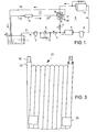
- FIG. 1 shows in detail a fuel tank 1, a suction line 2 open on the tank side, in which a pre-filter 3, a quantity measuring device 4 and a check valve 5 are switched on, and a closed fuel circuit 6, referred to as an injection circuit, in a known manner a certain amount of fuel - starting from the fuel delivery pump 7 via a main filter 8, the injection pump 9, a heat exchanger 10 and a feed valve 11 - is kept in circulation.
- a bypass 12 assigned to the quantity measuring device 4 serves to bypass it in the event of malfunctions.
- Another fuel circuit 13, referred to as the cooling circuit is maintained by an additional feed pump 14.
- This cooling circuit 13 is on the one hand in the heat exchanger 10 in close thermal contact with the injection circuit 6, on the other hand via a suction line 15 and a return line 16 in connection with the fuel tank 1, so that the heat exchanger 10, in the example shown in FIG. 1, as a the cooling circuit 13 associated, closed container 17 is formed with a cooling body 18 assigned to the injection circuit 6, always flows through of cool fuel from the fuel tank and thus heat removal, ie effective cooling is guaranteed.
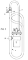
- tube material preferably copper tube material
- tube material is used both for the heat sink and for the container, with a first tube 19 of smaller diameter lying in a second tube 20 and both tubes 19, 20 are formed together into a coil 21 with a flat oval cross section.
- the outer diameter of the inner tube 19 (for example 10 mm) and the inner diameter of the outer tube 20 (for example 13 mm) are selected such that there is sufficient space for the fuel flow.
- Connection means for the line parts of the injection circuit 6 and the cooling circuit 13 to be connected are connected to the pipe ends, as shown in FIG.
- the feed pump 14 that operates the cooling circuit 13 is, as FIG. 2 further shows, attached to the coil 21 formed from the tubes 19 and 20 by means of suitable holding means 26 in such a way that it is located within the space enclosed by the tube turns, so that this space is used and a functional assembly is created. With 27 is used to complete this assembly, preferably flexible line part between the pump 14 and the heat exchanger 10.
- this particularly economical embodiment variant of a heat exchanger is preferably connected in such a way that the inner tube 10 is in the cooling circuit 13 and the outer tube 20 is in the injection circuit 6, so that the wind and radiation can also have a cooling effect.
Landscapes
- Engineering & Computer Science (AREA)
- Physics & Mathematics (AREA)
- Mechanical Engineering (AREA)
- General Engineering & Computer Science (AREA)
- Thermal Sciences (AREA)
- Chemical & Material Sciences (AREA)
- Combustion & Propulsion (AREA)
- Fluid Mechanics (AREA)
- General Physics & Mathematics (AREA)
- Fuel-Injection Apparatus (AREA)
- Heat-Exchange Devices With Radiators And Conduit Assemblies (AREA)
- Cooling, Air Intake And Gas Exhaust, And Fuel Tank Arrangements In Propulsion Units (AREA)
Applications Claiming Priority (2)
| Application Number | Priority Date | Filing Date | Title |
|---|---|---|---|
| DE19813107141 DE3107141A1 (de) | 1981-02-26 | 1981-02-26 | Anordnung zum kuehlen des kraftstoffs in einem betriebssystem eines dieselmotors mit einem geschlossenen einspritzkreislauf |
| DE3107141 | 1981-02-26 |
Publications (3)
| Publication Number | Publication Date |
|---|---|
| EP0059303A2 EP0059303A2 (de) | 1982-09-08 |
| EP0059303A3 EP0059303A3 (en) | 1983-10-26 |
| EP0059303B1 true EP0059303B1 (de) | 1985-12-18 |
Family
ID=6125768
Family Applications (1)
| Application Number | Title | Priority Date | Filing Date |
|---|---|---|---|
| EP82100183A Expired EP0059303B1 (de) | 1981-02-26 | 1982-01-13 | Anordnung zum Kühlen des Kraftstoffs in einem Betriebssystem eines Dieselmotors mit einem geschlossenen Einspritzkreislauf |
Country Status (4)
| Country | Link |
|---|---|
| US (1) | US4411239A (cg-RX-API-DMAC10.html) |
| EP (1) | EP0059303B1 (cg-RX-API-DMAC10.html) |
| JP (1) | JPS5863349U (cg-RX-API-DMAC10.html) |
| DE (2) | DE3107141A1 (cg-RX-API-DMAC10.html) |
Families Citing this family (61)
| Publication number | Priority date | Publication date | Assignee | Title |
|---|---|---|---|---|
| DE3304723A1 (de) * | 1983-02-11 | 1984-08-16 | Kienzle Apparate Gmbh, 7730 Villingen-Schwenningen | Anordnung einer einen zusatzkreislauf im betriebssystem eines dieselmotors speisende zusatzpumpe |
| FR2541377B1 (fr) * | 1983-02-22 | 1987-06-05 | Scoma Energie | Procede et dispositif d'echange thermique, en particulier pour le rechauffage du carburant dans les moteurs a combustion interne, notamment diesel |
| JPS59155564A (ja) * | 1983-02-24 | 1984-09-04 | Toyota Motor Corp | 燃料噴射式エンジンの燃料分配管 |
| BR8400424A (pt) * | 1984-01-25 | 1985-09-10 | B V Brana | Sistema de carburacao a vapor-redutor de consumo e poluicao para todos os tipos de motores |
| US4552015A (en) * | 1984-02-09 | 1985-11-12 | General Motors Corporation | Fuel consumption measuring system |
| GB8406270D0 (en) * | 1984-03-09 | 1984-04-11 | Lucas Ind Plc | Fuel system |
| EP0200733A1 (en) * | 1984-11-05 | 1986-11-12 | WOODS, John, T. | Fuel vaporization and injection system |
| FR2590939B1 (fr) * | 1985-12-04 | 1989-12-08 | Debeaux Michel | Dispositif de regulation de la temperature du carburant de moteurs et de bruleurs a gazole |
| DE3721834A1 (de) * | 1987-07-02 | 1989-01-12 | Eberspaecher J | Einrichtung zur vorwaermung von fluessigem brennstoff fuer heizgeraete in mobilen einheiten |
| IT1217257B (it) * | 1987-08-25 | 1990-03-22 | Weber Srl | Impianto di iniezione del combustibile con iniettori comandati per motori a ciclo diesel |
| IT1217256B (it) * | 1987-08-25 | 1990-03-22 | Weber Srl | Pompa di iniezione per impianti di iniezione del combustibile con iniettori comandati per motori a ciclo diesel |
| DE3825470A1 (de) * | 1988-07-27 | 1990-02-01 | Daimler Benz Ag | Fuer eine brennkraftmaschine vorgesehene kraftstoffversorgungseinrichtung |
| US4960088A (en) * | 1989-09-08 | 1990-10-02 | Thermo King Corporation | Low fuel shut-off system |
| US5020566A (en) * | 1990-08-13 | 1991-06-04 | Sullair Corporation | Fuel supply system for portable engine driven equipment |
| US5213086A (en) * | 1991-06-27 | 1993-05-25 | Carbco Technologies Inc. | Fuel inlet system for internal combustion engine |
| US5355860A (en) * | 1992-07-09 | 1994-10-18 | Ekstam Charles L | Fuel delivery system for diesel engines |
| US5746184A (en) * | 1992-07-09 | 1998-05-05 | Ekstam Patent, L.L.C. | Fuel delivery system for diesel engines |
| US5269276A (en) * | 1992-09-28 | 1993-12-14 | Ford Motor Company | Internal combustion engine fuel supply system |
| US5529314A (en) * | 1993-09-13 | 1996-06-25 | Ekstam; Charles L. | Pump shaft lubricated bearing fluid seal assembly |
| JPH07103022A (ja) * | 1993-10-05 | 1995-04-18 | Mitsubishi Electric Corp | 車両用エンジンの制御装置 |
| US5551404A (en) * | 1993-12-10 | 1996-09-03 | Coltec Industries Inc. | Fuel injection system for marine engines |
| US5533486A (en) * | 1993-12-23 | 1996-07-09 | Freightliner Corporation | Fuel system for heating and cooling fuel |
| US6195465B1 (en) | 1994-09-21 | 2001-02-27 | Ricoh Company, Ltd. | Method and apparatus for compression using reversible wavelet transforms and an embedded codestream |
| US5509392A (en) * | 1995-04-28 | 1996-04-23 | Schmitz; John J. | Anti-vapor lock fuel system |
| DE19547243A1 (de) * | 1995-12-18 | 1997-06-19 | Bayerische Motoren Werke Ag | Kraftstoff-Fördersystem |
| US5794598A (en) * | 1996-06-21 | 1998-08-18 | Stanadyne Automotive Corp. | Fuel circuit and circulation method for fuel injection system |
| DE19631981B4 (de) * | 1996-08-08 | 2006-02-09 | Volkswagen Ag | Vorrichtung zum Kühlen eines Kraftstoffes eines geschlossenen Kraftstoffversorgungskreislaufes eines Dieselaggregats |
| US5765537A (en) | 1997-01-17 | 1998-06-16 | Caterpillar Inc. | Fuel recirculation system |
| US5832903A (en) * | 1997-06-02 | 1998-11-10 | Brunswick Corp. | Fuel supply system for an internal combustion engine |
| DE19740057C1 (de) * | 1997-09-12 | 1999-01-21 | Mannesmann Vdo Ag | Kraftstoffversorgungssystem |
| US5988265A (en) * | 1998-02-17 | 1999-11-23 | Cummins Engine Company, Inc. | Fuel cooler and coolant filter assembly |
| US5964206A (en) * | 1998-05-06 | 1999-10-12 | Brunswick Corporation | Fuel supply cooling system for an internal combustion engine |
| US5887555A (en) * | 1998-06-23 | 1999-03-30 | Thermo Power Corporation | Cooling device for a fuel pump and fuel in a marine combustion engine |
| US6065455A (en) * | 1998-08-27 | 2000-05-23 | Allen N. Sharpe | Fuel delivery re-routing harness |
| US6397826B1 (en) * | 1998-12-18 | 2002-06-04 | Clean Fuel Technology, Inc. | Fuel cooling system for fuel emulsion based compression ignition engine |
| JP4311509B2 (ja) * | 1999-02-18 | 2009-08-12 | ヤマハ発動機株式会社 | 推進機用エンジン |
| DE19916530A1 (de) * | 1999-04-13 | 2000-10-19 | Mannesmann Vdo Ag | Einrichtung zur Versorgung einer Brennkraftmaschine eines Kraftfahrzeuges mit Kraftstoff |
| US6257208B1 (en) | 1999-08-17 | 2001-07-10 | Federal-Mogul World Wide, Inc. | Marine-vapor separator |
| US6341623B1 (en) * | 2000-08-25 | 2002-01-29 | Ford Global Technologies, Inc. | Variable orifice, pressure compensated automated fuel jet pump |
| US6457460B1 (en) * | 2000-11-13 | 2002-10-01 | Walbro Corporation | Fuel delivery system with recirculation cooler |
| US6729310B2 (en) | 2001-02-20 | 2004-05-04 | Charles L. Ekstam | Fuel delivery system |
| US6675641B2 (en) | 2001-06-21 | 2004-01-13 | Caterpillar Inc | Closed system transient diesel fuel conditioning and measurement system |
| JP4566473B2 (ja) * | 2001-07-24 | 2010-10-20 | 臼井国際産業株式会社 | 内燃機関における燃料冷却方法 |
| FR2831218B1 (fr) * | 2001-10-22 | 2004-03-19 | Peugeot Citroen Automobiles Sa | Systeme d'injection de carburant pour moteur diesel avec recyclage |
| DE10205186A1 (de) * | 2002-02-08 | 2003-08-21 | Bosch Gmbh Robert | Kraftstoffeinspritzeinrichtung für eine Brennkraftmaschine |
| DE10232514A1 (de) * | 2002-07-18 | 2004-01-29 | Daimlerchrysler Ag | Kraftstoffkühlung im Rücklauf eines druckübersetzten Einspritzsystems |
| US6892710B2 (en) * | 2003-02-21 | 2005-05-17 | Charles Bradley Ekstam | Fuel/air separation system |
| ITTO20030724A1 (it) * | 2003-09-19 | 2005-03-20 | Dayco Fuel Man Spa | Dispositivo di raffreddamento per un circuito di riciclo di carburante da un sistema di iniezione a un serbatoio di un autoveicolo |
| GB2407802A (en) * | 2003-11-05 | 2005-05-11 | Bombardier Transp Gmbh | Buffer fuel tank arrangement for rail vehicle |
| US7077110B2 (en) * | 2004-03-01 | 2006-07-18 | Stant Manufacturing Inc. | Return fuel temperature control module |
| JP2007285235A (ja) * | 2006-04-18 | 2007-11-01 | Honda Motor Co Ltd | ディーゼルエンジンの燃料供給装置 |
| DE102006036667A1 (de) * | 2006-08-03 | 2008-02-07 | Fev Motorentechnik Gmbh | Ermittlung des Kraftstoffverbrauchs einer Brennkraftmaschine |
| AT509405A1 (de) * | 2010-01-19 | 2011-08-15 | Bosch Gmbh Robert | Verfahren zum temperieren eines injektors einer einspritzung für das einspritzen von kraftstoff in den brennraum einer brennkraftmaschine |
| JP2012167559A (ja) * | 2011-02-10 | 2012-09-06 | Denso Corp | 燃料噴射装置 |
| US9038657B2 (en) * | 2011-05-06 | 2015-05-26 | Deere & Company | Fuel supply system having a recirculation loop capable of returnless operation |
| US8944032B2 (en) * | 2012-04-03 | 2015-02-03 | Deere & Company | Diesel fuel feed system |
| AT515306B1 (de) * | 2014-07-24 | 2015-08-15 | Avl List Gmbh | Kraftstoffverbrauchsmesssystem sowie Verfahren zur Messung eines Kraftstoffverbrauchs einer Verbrennungskraftmaschine |
| US9828931B1 (en) * | 2016-11-01 | 2017-11-28 | GM Global Technology Operations LLC | Diesel low pressure/high pressure flow control system |
| US20200232431A1 (en) * | 2019-01-18 | 2020-07-23 | Pratt & Whitney Canada Corp. | Method of managing heat of injector backflow |
| US10865728B2 (en) | 2019-01-18 | 2020-12-15 | Pratt & Whitney Canada Corp. | Method of using backflow from common-rail fuel injector |
| US10738749B1 (en) | 2019-01-18 | 2020-08-11 | Pratt & Whitney Canada Corp. | Method of using heat from fuel of common-rail injectors |
Family Cites Families (12)
| Publication number | Priority date | Publication date | Assignee | Title |
|---|---|---|---|---|
| US1319718A (en) * | 1919-10-28 | Lewis h | ||
| US990741A (en) * | 1908-10-12 | 1911-04-25 | Erd C Mullendore | Fuel-feeding means for explosive-engines. |
| US2599699A (en) * | 1947-05-13 | 1952-06-10 | Gen Motors Corp | Fuel system for combustion apparatus |
| US3213929A (en) * | 1962-02-12 | 1965-10-26 | Varian Associates | Temperature control system |
| US3672394A (en) * | 1970-05-22 | 1972-06-27 | Curtis L Erwin Jr | Fuel system for diesel engines |
| FR2324888A1 (fr) * | 1974-01-11 | 1977-04-15 | Fonagy Dezso | Dispositif de regularisation d'un courant d'essence d'alimentation d'un carburateur par pulverisation |
| NL153975B (nl) * | 1974-02-05 | 1977-07-15 | Doornes Bedrijfswagen Fab | Brandstofverbruikmeetinrichting voor een verbrandingsmotor. |
| GB1573703A (en) * | 1977-03-10 | 1980-08-28 | Plumbly S J | Fuel system |
| DE2715587C2 (de) * | 1977-04-07 | 1986-07-03 | Robert Bosch Gmbh, 7000 Stuttgart | Kraftstoffversorgungseinrichtung für Brennkraftmaschinen |
| DE7925973U1 (de) * | 1979-09-13 | 1979-12-06 | Kienzle Apparate Gmbh, 7730 Villingen-Schwenningen | Anordnung fuer ein betriebssystem eines dieselmotors mit geschlossenem kraftstoffkreislauf zum einfuehren des kraftstoffkreislaufs in den kraftstofftank |
| US4300514A (en) * | 1979-09-14 | 1981-11-17 | Josef Schaich | Device for vaporizing fuel and controlling the temperature of the fuel in an internal combustion engine |
| US4343283A (en) * | 1979-11-26 | 1982-08-10 | Shepherd Clarence R | Diesel engine fuel preheating system |
-
1981
- 1981-02-26 DE DE19813107141 patent/DE3107141A1/de not_active Withdrawn
-
1982
- 1982-01-13 DE DE8282100183T patent/DE3267949D1/de not_active Expired
- 1982-01-13 EP EP82100183A patent/EP0059303B1/de not_active Expired
- 1982-02-16 US US06/349,270 patent/US4411239A/en not_active Expired - Fee Related
- 1982-02-25 JP JP1982024959U patent/JPS5863349U/ja active Granted
Also Published As
| Publication number | Publication date |
|---|---|
| DE3107141A1 (de) | 1982-09-09 |
| JPS5863349U (ja) | 1983-04-28 |
| EP0059303A3 (en) | 1983-10-26 |
| US4411239A (en) | 1983-10-25 |
| EP0059303A2 (de) | 1982-09-08 |
| DE3267949D1 (en) | 1986-01-30 |
| JPS622289Y2 (cg-RX-API-DMAC10.html) | 1987-01-20 |
Similar Documents
| Publication | Publication Date | Title |
|---|---|---|
| EP0059303B1 (de) | Anordnung zum Kühlen des Kraftstoffs in einem Betriebssystem eines Dieselmotors mit einem geschlossenen Einspritzkreislauf | |
| EP0239788B1 (de) | Anordnung zur Gasabscheidung | |
| DE112011103943T5 (de) | Integriertes SCR-Speichergerät für Reduktionsmittel | |
| DE3624261C2 (de) | Warmwasserspeicher, insbesondere Schichtenspeicher | |
| DE102005018560B4 (de) | Rohrverbindung | |
| DE69722966T2 (de) | Verlängerter zylinderkopf für eine dieselbrennkraftmaschine ,mit löchern für einspritzeinheiten und brennstoffzufuhr | |
| DE102021208930B4 (de) | Verteilungseinrichtung und Flüssigkeitsverteilungsaktuator | |
| DE2934753A1 (de) | Filteranlage | |
| DE102008028854A1 (de) | Verdampfer und Kältemaschine oder Wärmepumpe | |
| DE2435018A1 (de) | Dosiervorrichtung fuer zentralschmiersysteme | |
| DE7925973U1 (de) | Anordnung fuer ein betriebssystem eines dieselmotors mit geschlossenem kraftstoffkreislauf zum einfuehren des kraftstoffkreislaufs in den kraftstofftank | |
| DE3303500A1 (de) | Waermetauscher, insbesondere fuer den kuehlmittelkreis einer brennkraftmaschine | |
| EP2530409A2 (de) | Wärmepumpenanlage sowie Verfahren zum Betrieb einer Wärmepumpenanlage | |
| WO1982000330A1 (en) | Installation for preventing the formation of cracks at the inner surface of the sleeve of a water supply conduit opening into pressure tanks | |
| DE10126916B4 (de) | Warmwasserspeichervorrichtung | |
| EP2638592A1 (de) | Kühlmittelkreis für ein brennstoffzellensystem und verfahren zum austauschen von ionenaustauschermaterial | |
| DE102016110958A1 (de) | Wärmetauscher mit deionisierender Patrone | |
| DE10118343A1 (de) | Heizungsanlage | |
| AT524588B1 (de) | Warmwasserbereitungsanlage | |
| DE3323031A1 (de) | Schiff | |
| DE102004005621A1 (de) | Vorrichtung zum Austausch von Wärme und Verfahren zur Herstellung einer derartigen Vorrichtung | |
| DE3023089C2 (de) | Duo-Kältemittelverdampfer | |
| DE102019104506B3 (de) | Wassertankvorrichtung für eine Verbrennungskraftmaschine und Verfahren zum Betreiben einer Wassertankvorrichtung einer Verbrennungskraftmaschine | |
| DE8118566U1 (de) | Anordnung zum einfuehren einer ansaug- und einer rueckflussleitung in ein und dieselbe oeffnung eines tanks | |
| DE102022201020A1 (de) | Vorrichtung und Verfahren zur Rezirkulation von Anodengas in einem Anodenkreis eines Brennstoffzellensystems, Brennstoffzellensystem |
Legal Events
| Date | Code | Title | Description |
|---|---|---|---|
| PUAI | Public reference made under article 153(3) epc to a published international application that has entered the european phase |
Free format text: ORIGINAL CODE: 0009012 |
|
| AK | Designated contracting states |
Designated state(s): DE FR GB SE |
|
| PUAL | Search report despatched |
Free format text: ORIGINAL CODE: 0009013 |
|
| AK | Designated contracting states |
Designated state(s): DE FR GB SE |
|
| 17P | Request for examination filed |
Effective date: 19840215 |
|
| GRAA | (expected) grant |
Free format text: ORIGINAL CODE: 0009210 |
|
| AK | Designated contracting states |
Designated state(s): DE FR GB SE |
|
| REF | Corresponds to: |
Ref document number: 3267949 Country of ref document: DE Date of ref document: 19860130 |
|
| RAP2 | Party data changed (patent owner data changed or rights of a patent transferred) |
Owner name: MANNESMANN KIENZLE GMBH |
|
| ET | Fr: translation filed | ||
| PLBE | No opposition filed within time limit |
Free format text: ORIGINAL CODE: 0009261 |
|
| STAA | Information on the status of an ep patent application or granted ep patent |
Free format text: STATUS: NO OPPOSITION FILED WITHIN TIME LIMIT |
|
| 26N | No opposition filed | ||
| REG | Reference to a national code |
Ref country code: GB Ref legal event code: 746 |
|
| PGFP | Annual fee paid to national office [announced via postgrant information from national office to epo] |
Ref country code: SE Payment date: 19921228 Year of fee payment: 12 |
|
| REG | Reference to a national code |
Ref country code: FR Ref legal event code: DL |
|
| PG25 | Lapsed in a contracting state [announced via postgrant information from national office to epo] |
Ref country code: SE Effective date: 19940114 |
|
| EUG | Se: european patent has lapsed |
Ref document number: 82100183.1 Effective date: 19940810 |
|
| PGFP | Annual fee paid to national office [announced via postgrant information from national office to epo] |
Ref country code: FR Payment date: 19951219 Year of fee payment: 15 |
|
| PG25 | Lapsed in a contracting state [announced via postgrant information from national office to epo] |
Ref country code: FR Effective date: 19970930 |
|
| REG | Reference to a national code |
Ref country code: FR Ref legal event code: ST |
|
| PGFP | Annual fee paid to national office [announced via postgrant information from national office to epo] |
Ref country code: DE Payment date: 19990208 Year of fee payment: 18 |
|
| PG25 | Lapsed in a contracting state [announced via postgrant information from national office to epo] |
Ref country code: DE Free format text: LAPSE BECAUSE OF NON-PAYMENT OF DUE FEES Effective date: 20001101 |
|
| PGFP | Annual fee paid to national office [announced via postgrant information from national office to epo] |
Ref country code: GB Payment date: 20001212 Year of fee payment: 20 |
|
| REG | Reference to a national code |
Ref country code: GB Ref legal event code: IF02 |
|
| PG25 | Lapsed in a contracting state [announced via postgrant information from national office to epo] |
Ref country code: GB Free format text: LAPSE BECAUSE OF EXPIRATION OF PROTECTION Effective date: 20020112 |
|
| REG | Reference to a national code |
Ref country code: GB Ref legal event code: PE20 Effective date: 20020112 |