EP0054687B1 - Dispositifs de guidage pour les surfaces portantes de transporteurs à bande sans fin tels qu'escaliers roulants et analogues - Google Patents
Dispositifs de guidage pour les surfaces portantes de transporteurs à bande sans fin tels qu'escaliers roulants et analogues Download PDFInfo
- Publication number
- EP0054687B1 EP0054687B1 EP81108919A EP81108919A EP0054687B1 EP 0054687 B1 EP0054687 B1 EP 0054687B1 EP 81108919 A EP81108919 A EP 81108919A EP 81108919 A EP81108919 A EP 81108919A EP 0054687 B1 EP0054687 B1 EP 0054687B1
- Authority
- EP
- European Patent Office
- Prior art keywords
- rail
- rail holder
- dovetail
- guiding device
- fastening
- Prior art date
- Legal status (The legal status is an assumption and is not a legal conclusion. Google has not performed a legal analysis and makes no representation as to the accuracy of the status listed.)
- Expired
Links
Images

Classifications
-
- B—PERFORMING OPERATIONS; TRANSPORTING
- B66—HOISTING; LIFTING; HAULING
- B66B—ELEVATORS; ESCALATORS OR MOVING WALKWAYS
- B66B23/00—Component parts of escalators or moving walkways
- B66B23/14—Guiding means for carrying surfaces
-
- Y—GENERAL TAGGING OF NEW TECHNOLOGICAL DEVELOPMENTS; GENERAL TAGGING OF CROSS-SECTIONAL TECHNOLOGIES SPANNING OVER SEVERAL SECTIONS OF THE IPC; TECHNICAL SUBJECTS COVERED BY FORMER USPC CROSS-REFERENCE ART COLLECTIONS [XRACs] AND DIGESTS
- Y10—TECHNICAL SUBJECTS COVERED BY FORMER USPC
- Y10T—TECHNICAL SUBJECTS COVERED BY FORMER US CLASSIFICATION
- Y10T403/00—Joints and connections
- Y10T403/16—Joints and connections with adjunctive protector, broken parts retainer, repair, assembly or disassembly feature
- Y10T403/1616—Position or guide means
Definitions
- the present invention relates to a guide device for the running elements of endless conveyors such as escalators and the like, in which main and trailing rails are fastened to a carrier frame via rail holders.
- the running elements are supported and guided along their endless path, with the aim of achieving a running of these running elements that is as quiet and vibration-free as possible.
- the guide devices also serve to horizontally guide the tread surface of the running elements designed as stair treads as they pass through the upper run, both in the horizontal and in the ascending area and in the transitions.
- the running tracks subject to wear are generally connected to the support frame in a manner which is difficult to detach or even inseparable, so that there is no possibility of subjecting them to a surface treatment, regardless of the support frame, or of rapidly and easily replacing them if there is increased wear .
- the invention seeks to remedy this.
- the invention as characterized in the claims, solves the problem of creating a guide device for endless conveyors such as escalators and the like, which can be assembled with great effort and without any device on the construction site with great accuracy and whose running rails can be easily removed and replaced can.
- the innovation also aims to create a guiding device that can be constructed from a few standard parts that are manufactured in large series and that simplifies storage and makes production cheaper.
- the rail holder carrying the main and trailing rail has at least two centering knobs engaging in corresponding centering openings of a side plate fastened to the support frame on its fastening side provided with at least one fastening hole receiving fastening means and a dovetail clamping device on its rail support side which is perpendicular to the fastening side for accommodating the underside of the rail, which is designed in the shape of a dovetail, the dovetail clamping device consisting of a fixed jaw arranged on the rail holder and a movable jaw which can be fastened to the rail holder by means of a dovetail connection.
- the centering knobs and the fastening hole on the rail holder are arranged in mirror symmetry with respect to the middle of the rail holder that is perpendicular to the fastening and rail support side.
- the rail supports in the dovetail clamping devices are chamfered in the area of the run-in and running-out of the running rails.
- the rail holder has either a rectangular or an L-shaped cutting surface in the central plane of the rail holder.
- the L-shaped rail holder is equipped with a finger-shaped extension to brace the mating guides between its long side and the side plate.
- the guide device according to the invention is excellently suitable for assembly on the spot where work often has to be carried out under difficult conditions due to structural or other difficulties. Any shortcomings in the execution of the work cannot have a detrimental effect on the synchronism of the running elements, since the accuracy of the step guidance is determined by the prefabricated individual parts manufactured with tight tolerances.
- the modular assembly elements according to the invention are designed in such a way that they can be easily assembled on site as well as easily disassembled and have a relatively low weight.
- the tracks subject to wear can be easily removed for maintenance or replacement by loosening the dovetail clamp and reassembled without a device.
- the essential elements of the construction concept according to the invention namely the rail holder, the counter-guide, the rivet and screw connections and the dovetail clamping device are function-related and not system-related, that is, they can be used again and again independently of a system in the same design.
- the adaptation for the individual application takes place via the side plates or by positioning the corresponding centering openings.
- connection technology With regard to the construction elements such as the connection technology, one can therefore speak of a modular structure. For a large number of systems, such as For the standard widths of 80 cm and 110 cm, the same individual parts can be used, which are produced in standard sizes and which are characterized by easy handling and variety of possible uses.
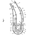
- Fig. 1 shows the guide device according to the invention based on the lower end of the stairs, how the step-shaped platforms are brought out of their inclined path into the horizontal path or vice versa and reverse their direction of movement.
- the following considerations apply mutatis mutandis to the sloping section and the top of the stairs, both of which are not shown here.
- Continuous escalators are usually driven by an upper sprocket, which sits on a motor-driven main shaft, and consist of a large number of stepped platforms, which are articulated on both sides. At the bottom of the stairs, the chain runs around idler sprockets 1, 2, which are often under the influence of a tension spring to maintain the chain tension, as is familiar to the person skilled in the escalator technology.
- both rail systems have main rails 3 for the chain rollers on the sides of the stairs, whereby in the area of the order Sweeping stations counter guides 4 are mounted. Trailing rails 5 are provided for the trailing rollers, which, however, only extend over the ends of the stairs in the lower run.
- the main rails 3.1 and the follower rails 5.1 are curved between the inclined sections and the horizontal sections in order to effect the step transition required here. In addition, the distance between the curved main rails 3.1 and trailing rails 5.1 changes constantly in this area in the upper run in order to ensure the gradual transition from platform to step - or vice versa depending on the direction of the step.
- the main rails are designed as channel-shaped guides 6 with a semicircular end part 7.
- the running rails 3, 5 in their various forms of construction are assembled without a device by means of rail holders 10, 11 and additional structural elements, with the carrier frame being manufactured on the basis of narrow tolerances Individual parts, the parallelism and the alignment of the running tracks are automatically guaranteed.
- two embodiments of the rail holder are required for the corresponding vertical and horizontal positioning of the rails: a rectangular rail holder 10 and an L-shaped rail holder 11.
- the rail holders thus act as central connecting elements between the support frame and the rails.
- the side plates 20 are initially to be screwed to the separately machined U-shaped cross member 21.
- the centering knobs 26, 27 on the rail holders 10, 11 are then brought into engagement with the corresponding centering openings 28, 29 in the side plates 20, thereby fixing the rail holders and side plates in their mutual position and connecting them to one another by means of the fastening means 30 in the fastening hole 31.
- the Spanniet 32 used here can be replaced by a screw or any other releasable or non-releasable connection means.
- the side plates 20 fulfill the double function as a precision template during assembly and as support elements for the rail holders.
- the rail holders 10, 11 each have a dovetail clamping device 35 on their rail support side 10.1, 11.1, which serves to clamp the running rails 3, 5 on all sides.
- the principle of device-less assembly is consistently continued when fastening the drawn counter-guides 4. The same are inserted into the rail holder 11 up to the stop 22 of the finger-shaped extension 23 and braced with it on the side plate 20.
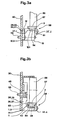
- FIG. 3a The assembly of the rail holder, side plate and running rail according to the invention is shown in detail in FIG. 3a for a rectangular rail holder 10 and in FIG. 3b for an L-shaped rail holder 11. "The following description of the connection construction applies in the same way to both types of rail holder.
- Both the rectangular and the L-shaped rail holder are provided on their fastening side 10.2, 11.2 with two centering knobs 26, 27 and have a dovetail clamping device 35 on the rail support side 10.1, 11.1.
- the fastening hole 48 serves to receive a fastening means for the construction of the rail holder on the side plate 20.
- the side plates 20 are provided in the area of the rail supports 10, 11 with centering openings 28, 29 which serve as reference points and, in cooperation with the centering knobs 26, 27 on the rail holders 10, 11, determine the parallelism and alignment of the running rails.
- the main and trailing rails 3, 5 have a dovetail-shaped profile 54 along their underside in order to be clamped in the dovetail clamping device 35, which has a fixed 35.1 and a movable jaw 35.2.
- the centering knobs 26, 27 on the rail holders 10, 11 are brought into engagement with the corresponding centering openings 28, 29 in the side plate 20, and the whole is connected by a rivet connection 55.
- the Spanniet was chosen for cost reasons, but is not intended to limit the invention in any way. A connection with a screw or other fastening means is also conceivable.
- the centering knobs 26, 27 In cooperation with the centering openings 28, 29, the centering knobs 26, 27 not only ensure the exact positioning of the rail holders on the side plate, but they also essentially take over the thrust forces that occur.
- the rivet or screw connection 55 only serves to absorb the tensile force resulting from the tilting moment.
- the dovetail clamping device 35 fixes the main and trailing rails 3, 5, on the running surfaces 57 of which the chain and drag rollers 58, 59 move, rigidly on all sides on the rail holders 10, 11.
- the dovetail profile 54 which extends along the entire length of the running rails 3, 5, ideally serves to hold the running rails rigidly but easily detachably on the rail supports by clamping. With a sufficient moment of inertia, the dovetail-shaped profile of the running rails enables a secure fastening of the running track, which ensures sufficient parallelism and alignment of the running rails even when the escalator is heavily loaded.
- bevels 56 are provided in the area of the rail runs and outflows in order to be able to better accommodate the running rails bent in the transition area from the horizontal part to the inclined part.
- the cant 61 is required if a force rivet 55 is used as the connecting means. With it, the span of the connection given by the side plate and the rail support should be adapted to the rivet used, since it is only commercially available in graded lengths.
- the width difference between the lower and the upper rail holder in the vicinity of the main and trailing rails is spanned with the intermediate plate 12. This measure makes it possible to meet all the requirements of escalator construction with only two types of rail holders, namely a rectangular and an L-shaped rail holder 10 and 11.
Landscapes
- Escalators And Moving Walkways (AREA)
- Structure Of Belt Conveyors (AREA)
- Handcart (AREA)
- Preparation Of Compounds By Using Micro-Organisms (AREA)
- Breeding Of Plants And Reproduction By Means Of Culturing (AREA)
- Pharmaceuticals Containing Other Organic And Inorganic Compounds (AREA)
- Belt Conveyors (AREA)
- Intermediate Stations On Conveyors (AREA)
- Discharge Of Articles From Conveyors (AREA)
Claims (7)
Priority Applications (1)
| Application Number | Priority Date | Filing Date | Title |
|---|---|---|---|
| AT81108919T ATE10926T1 (de) | 1980-12-23 | 1981-10-26 | Fuehrungseinrichtung fuer die laufelelemente von endlosfoerderern wie fahrtreppen und dergleichen. |
Applications Claiming Priority (2)
| Application Number | Priority Date | Filing Date | Title |
|---|---|---|---|
| CH9514/80 | 1980-12-23 | ||
| CH9514/80A CH648811A5 (de) | 1980-12-23 | 1980-12-23 | Fuehrungseinrichtung fuer die laufelemente von endlosfoerderern, insbesondere fahrtreppen. |
Publications (2)
| Publication Number | Publication Date |
|---|---|
| EP0054687A1 EP0054687A1 (fr) | 1982-06-30 |
| EP0054687B1 true EP0054687B1 (fr) | 1984-12-27 |
Family
ID=4352795
Family Applications (1)
| Application Number | Title | Priority Date | Filing Date |
|---|---|---|---|
| EP81108919A Expired EP0054687B1 (fr) | 1980-12-23 | 1981-10-26 | Dispositifs de guidage pour les surfaces portantes de transporteurs à bande sans fin tels qu'escaliers roulants et analogues |
Country Status (8)
| Country | Link |
|---|---|
| US (1) | US4484674A (fr) |
| EP (1) | EP0054687B1 (fr) |
| AT (1) | ATE10926T1 (fr) |
| CH (1) | CH648811A5 (fr) |
| DE (1) | DE3167978D1 (fr) |
| ES (1) | ES8304880A1 (fr) |
| FI (1) | FI68594C (fr) |
| GB (1) | GB2089753B (fr) |
Cited By (1)
| Publication number | Priority date | Publication date | Assignee | Title |
|---|---|---|---|---|
| US11066275B2 (en) | 2019-01-23 | 2021-07-20 | Otis Elevator Company | Conveyance belt for a conveyor |
Families Citing this family (13)
| Publication number | Priority date | Publication date | Assignee | Title |
|---|---|---|---|---|
| US4662502A (en) * | 1983-10-12 | 1987-05-05 | Mitsubishi Denki Kabushiki Kaisha | Curved escalator |
| DE3635879C1 (de) * | 1986-10-22 | 1988-02-11 | Uwe Kochanneck | Arbeitsplatz |
| DE3742309A1 (de) * | 1987-12-14 | 1989-06-29 | Orenstein & Koppel Ag | Laufschienenprofil fuer die rollen eines rollsteiges |
| US4961492A (en) * | 1988-07-22 | 1990-10-09 | Simplimatic Engineering Company | Article carrying conveyor and wearstrip set therefor |
| SE516848C2 (sv) * | 2000-07-05 | 2002-03-12 | Flexlink Components Ab | Brytanordning till transportör |
| JP4292104B2 (ja) * | 2004-05-06 | 2009-07-08 | 株式会社日立製作所 | 乗客コンベア |
| ES2299408B1 (es) * | 2007-10-18 | 2009-06-12 | Thyssenkrupp Elevator (Es/Pbb) Ltd. | Sistema de guiado autoportante para pasillos rodantes. |
| CN101239688B (zh) * | 2008-03-14 | 2011-01-12 | 浙江西子重工机械有限公司 | 扶梯侧板及其加工方法 |
| EP2433893A1 (fr) * | 2010-09-24 | 2012-03-28 | Inventio AG | Dispositif de transport de personnes |
| JP6373492B2 (ja) * | 2015-06-03 | 2018-08-15 | 三菱電機株式会社 | 乗客コンベアの踏段流れ調整装置 |
| DE102017130730A1 (de) * | 2017-12-20 | 2019-06-27 | Thyssenkrupp Ag | Umführung für Außenrollenketten einer Personenbeförderungsvorrichtung |
| DE102018213647A1 (de) * | 2018-08-14 | 2019-08-01 | Thyssenkrupp Ag | Führungsschienenhaltesystem für eine Fahrtreppe |
| WO2022135860A1 (fr) * | 2020-12-21 | 2022-06-30 | Inventio Ag | Dispositif de fixation de rail pour des sections de rail de guidage d'un escalier roulant ou d'un trottoir roulant |
Family Cites Families (8)
| Publication number | Priority date | Publication date | Assignee | Title |
|---|---|---|---|---|
| US1958162A (en) * | 1930-03-15 | 1934-05-08 | West Virginia Rail Company | Track construction |
| US1956155A (en) * | 1932-09-22 | 1934-04-24 | Otis Elevator Co | Moving stairway |
| US2686585A (en) * | 1949-05-04 | 1954-08-17 | Otis Elevator Co | Moving stairway |
| US2936872A (en) * | 1957-05-24 | 1960-05-17 | Rheinstahl Hamburg Stahlbau Eg | Moving stairways |
| US3707220A (en) * | 1970-11-23 | 1972-12-26 | Westinghouse Electric Corp | Modular passenger conveyor construction |
| US3834513A (en) * | 1971-12-20 | 1974-09-10 | Hitachi Ltd | Guide rail means |
| US4046248A (en) * | 1974-01-15 | 1977-09-06 | Chemcut Corporation | Connecting and alignment means for modular chemical treatment system |
| AT330655B (de) * | 1974-11-15 | 1976-07-12 | Wertheim Werke Ag | Tragwerk, insbesondere fur rolltreppen od.dgl. |
-
1980
- 1980-12-23 CH CH9514/80A patent/CH648811A5/de not_active IP Right Cessation
-
1981
- 1981-10-22 GB GB8131931A patent/GB2089753B/en not_active Expired
- 1981-10-26 EP EP81108919A patent/EP0054687B1/fr not_active Expired
- 1981-10-26 AT AT81108919T patent/ATE10926T1/de not_active IP Right Cessation
- 1981-10-26 DE DE8181108919T patent/DE3167978D1/de not_active Expired
- 1981-11-13 FI FI813602A patent/FI68594C/fi not_active IP Right Cessation
- 1981-11-30 US US06/325,929 patent/US4484674A/en not_active Expired - Lifetime
- 1981-12-23 ES ES508329A patent/ES8304880A1/es not_active Expired
Cited By (1)
| Publication number | Priority date | Publication date | Assignee | Title |
|---|---|---|---|---|
| US11066275B2 (en) | 2019-01-23 | 2021-07-20 | Otis Elevator Company | Conveyance belt for a conveyor |
Also Published As
| Publication number | Publication date |
|---|---|
| FI813602L (fi) | 1982-06-24 |
| GB2089753A (en) | 1982-06-30 |
| ES508329A0 (es) | 1983-04-01 |
| US4484674A (en) | 1984-11-27 |
| CH648811A5 (de) | 1985-04-15 |
| GB2089753B (en) | 1984-07-18 |
| FI68594B (fi) | 1985-06-28 |
| ES8304880A1 (es) | 1983-04-01 |
| DE3167978D1 (en) | 1985-02-07 |
| ATE10926T1 (de) | 1985-01-15 |
| FI68594C (fi) | 1985-10-10 |
| EP0054687A1 (fr) | 1982-06-30 |
Similar Documents
| Publication | Publication Date | Title |
|---|---|---|
| EP0054687B1 (fr) | Dispositifs de guidage pour les surfaces portantes de transporteurs à bande sans fin tels qu'escaliers roulants et analogues | |
| DE3502820A1 (de) | Fertigungsanlage mit mehreren einzelstationen | |
| DE4243812C2 (de) | Schiffs-Förderanlage | |
| DE2157423A1 (de) | Endlos umlaufende Vorrichtung zur Beförderung von Personen von einer Anschlußstelle zur nächsten wie Rolltreppe o. dgl | |
| DE2546915A1 (de) | Vorrichtung zum aufhaengen und antreiben von haengetueren | |
| DE4006486B4 (de) | Gehäuseteil für eine Arbeits- oder Bearbeitungsstation einer Fertigungsanlage | |
| DE2401503C3 (de) | Übergabeeinrichtung für Werkstückträger an den Übergabestationen einer Transferstraße | |
| DE3905780C1 (fr) | ||
| WO1987004412A1 (fr) | Transporteur de pieces a usiner | |
| CH667229A5 (de) | Maschinentisch in modulbauweise fuer fertigungseinrichtungen. | |
| DE3922397C2 (fr) | ||
| DE3302266C2 (de) | Weiche für eine Einschienenhängebahn | |
| DE60034433T2 (de) | Einrichtung und verfahren zum führungsschieneneinbau | |
| DE10059312C2 (de) | Zentriervorrichtung für Fördergut | |
| DE2516500C2 (fr) | ||
| EP0327652A1 (fr) | Procédé pour l'assemblage de la voie d'un convoyeur à rouleaux utilisant des profilés ainsi que voie d'un convoyeur à rouleaux | |
| DE19532391A1 (de) | Antriebseinheit für ein endloses Fördermittel eines Fördersystem | |
| EP0524538A1 (fr) | Longeron de support pour chaîne de convoyeur accumulateur à rouleaux | |
| DE2027191A1 (de) | Verfahren zum Transportieren, Positionieren und Festspannen von Werkstücken, insbesondere aus Holz, beispielsweise Holzplatten, an mindestens einer Bearbeitungsstation sowie Einrichtung zur Durchführung dieses Verfahrens | |
| DE19805574B4 (de) | Verfahren und Vorrichtung zum Transport und zur Vorbereitung von hohlen Profilstäben aus Kunststoff für die Bildung von Fensterrahmen | |
| DE8126440U1 (de) | Rahmen fuer bandfoerdervorrichtungen | |
| EP0253238B1 (fr) | Rayonnage avec unités de rayonnage déplaçables | |
| DE4219091C2 (de) | Förderlinie | |
| DE2160253B2 (de) | Transport- und Führungseinrichtung einer Vorrichtung zum Ausgießen von Kanälen in Profilstäben mit wärmeisolierenden Kunststoffmaterialien | |
| DE3729807C2 (fr) |
Legal Events
| Date | Code | Title | Description |
|---|---|---|---|
| PUAI | Public reference made under article 153(3) epc to a published international application that has entered the european phase |
Free format text: ORIGINAL CODE: 0009012 |
|
| AK | Designated contracting states |
Designated state(s): AT BE DE FR IT NL |
|
| 17P | Request for examination filed |
Effective date: 19821014 |
|
| ITF | It: translation for a ep patent filed |
Owner name: MODIANO & ASSOCIATI S.R.L. |
|
| GRAA | (expected) grant |
Free format text: ORIGINAL CODE: 0009210 |
|
| AK | Designated contracting states |
Designated state(s): AT BE DE FR IT NL |
|
| REF | Corresponds to: |
Ref document number: 10926 Country of ref document: AT Date of ref document: 19850115 Kind code of ref document: T |
|
| REF | Corresponds to: |
Ref document number: 3167978 Country of ref document: DE Date of ref document: 19850207 |
|
| ET | Fr: translation filed | ||
| PLBE | No opposition filed within time limit |
Free format text: ORIGINAL CODE: 0009261 |
|
| STAA | Information on the status of an ep patent application or granted ep patent |
Free format text: STATUS: NO OPPOSITION FILED WITHIN TIME LIMIT |
|
| 26N | No opposition filed | ||
| ITTA | It: last paid annual fee | ||
| PGFP | Annual fee paid to national office [announced via postgrant information from national office to epo] |
Ref country code: NL Payment date: 20000925 Year of fee payment: 20 |
|
| PGFP | Annual fee paid to national office [announced via postgrant information from national office to epo] |
Ref country code: AT Payment date: 20000926 Year of fee payment: 20 |
|
| PGFP | Annual fee paid to national office [announced via postgrant information from national office to epo] |
Ref country code: DE Payment date: 20001005 Year of fee payment: 20 |
|
| PGFP | Annual fee paid to national office [announced via postgrant information from national office to epo] |
Ref country code: BE Payment date: 20001020 Year of fee payment: 20 |
|
| PGFP | Annual fee paid to national office [announced via postgrant information from national office to epo] |
Ref country code: FR Payment date: 20001030 Year of fee payment: 20 |
|
| BE20 | Be: patent expired |
Free format text: 20011026 *INVENTIO A.G. |
|
| PG25 | Lapsed in a contracting state [announced via postgrant information from national office to epo] |
Ref country code: NL Free format text: LAPSE BECAUSE OF EXPIRATION OF PROTECTION Effective date: 20011026 Ref country code: AT Free format text: LAPSE BECAUSE OF EXPIRATION OF PROTECTION Effective date: 20011026 |
|
| NLV7 | Nl: ceased due to reaching the maximum lifetime of a patent |
Effective date: 20011026 |