EP0054687B1 - Guiding device for carrying surfaces of endless belt conveyors such as escalators and the like - Google Patents
Guiding device for carrying surfaces of endless belt conveyors such as escalators and the like Download PDFInfo
- Publication number
- EP0054687B1 EP0054687B1 EP81108919A EP81108919A EP0054687B1 EP 0054687 B1 EP0054687 B1 EP 0054687B1 EP 81108919 A EP81108919 A EP 81108919A EP 81108919 A EP81108919 A EP 81108919A EP 0054687 B1 EP0054687 B1 EP 0054687B1
- Authority
- EP
- European Patent Office
- Prior art keywords
- rail
- rail holder
- dovetail
- guiding device
- fastening
- Prior art date
- Legal status (The legal status is an assumption and is not a legal conclusion. Google has not performed a legal analysis and makes no representation as to the accuracy of the status listed.)
- Expired
Links
Images

Classifications
-
- B—PERFORMING OPERATIONS; TRANSPORTING
- B66—HOISTING; LIFTING; HAULING
- B66B—ELEVATORS; ESCALATORS OR MOVING WALKWAYS
- B66B23/00—Component parts of escalators or moving walkways
- B66B23/14—Guiding means for carrying surfaces
-
- Y—GENERAL TAGGING OF NEW TECHNOLOGICAL DEVELOPMENTS; GENERAL TAGGING OF CROSS-SECTIONAL TECHNOLOGIES SPANNING OVER SEVERAL SECTIONS OF THE IPC; TECHNICAL SUBJECTS COVERED BY FORMER USPC CROSS-REFERENCE ART COLLECTIONS [XRACs] AND DIGESTS
- Y10—TECHNICAL SUBJECTS COVERED BY FORMER USPC
- Y10T—TECHNICAL SUBJECTS COVERED BY FORMER US CLASSIFICATION
- Y10T403/00—Joints and connections
- Y10T403/16—Joints and connections with adjunctive protector, broken parts retainer, repair, assembly or disassembly feature
- Y10T403/1616—Position or guide means
Definitions
- the present invention relates to a guide device for the running elements of endless conveyors such as escalators and the like, in which main and trailing rails are fastened to a carrier frame via rail holders.
- the running elements are supported and guided along their endless path, with the aim of achieving a running of these running elements that is as quiet and vibration-free as possible.
- the guide devices also serve to horizontally guide the tread surface of the running elements designed as stair treads as they pass through the upper run, both in the horizontal and in the ascending area and in the transitions.
- the running tracks subject to wear are generally connected to the support frame in a manner which is difficult to detach or even inseparable, so that there is no possibility of subjecting them to a surface treatment, regardless of the support frame, or of rapidly and easily replacing them if there is increased wear .
- the invention seeks to remedy this.
- the invention as characterized in the claims, solves the problem of creating a guide device for endless conveyors such as escalators and the like, which can be assembled with great effort and without any device on the construction site with great accuracy and whose running rails can be easily removed and replaced can.
- the innovation also aims to create a guiding device that can be constructed from a few standard parts that are manufactured in large series and that simplifies storage and makes production cheaper.
- the rail holder carrying the main and trailing rail has at least two centering knobs engaging in corresponding centering openings of a side plate fastened to the support frame on its fastening side provided with at least one fastening hole receiving fastening means and a dovetail clamping device on its rail support side which is perpendicular to the fastening side for accommodating the underside of the rail, which is designed in the shape of a dovetail, the dovetail clamping device consisting of a fixed jaw arranged on the rail holder and a movable jaw which can be fastened to the rail holder by means of a dovetail connection.
- the centering knobs and the fastening hole on the rail holder are arranged in mirror symmetry with respect to the middle of the rail holder that is perpendicular to the fastening and rail support side.
- the rail supports in the dovetail clamping devices are chamfered in the area of the run-in and running-out of the running rails.
- the rail holder has either a rectangular or an L-shaped cutting surface in the central plane of the rail holder.
- the L-shaped rail holder is equipped with a finger-shaped extension to brace the mating guides between its long side and the side plate.
- the guide device according to the invention is excellently suitable for assembly on the spot where work often has to be carried out under difficult conditions due to structural or other difficulties. Any shortcomings in the execution of the work cannot have a detrimental effect on the synchronism of the running elements, since the accuracy of the step guidance is determined by the prefabricated individual parts manufactured with tight tolerances.
- the modular assembly elements according to the invention are designed in such a way that they can be easily assembled on site as well as easily disassembled and have a relatively low weight.
- the tracks subject to wear can be easily removed for maintenance or replacement by loosening the dovetail clamp and reassembled without a device.
- the essential elements of the construction concept according to the invention namely the rail holder, the counter-guide, the rivet and screw connections and the dovetail clamping device are function-related and not system-related, that is, they can be used again and again independently of a system in the same design.
- the adaptation for the individual application takes place via the side plates or by positioning the corresponding centering openings.
- connection technology With regard to the construction elements such as the connection technology, one can therefore speak of a modular structure. For a large number of systems, such as For the standard widths of 80 cm and 110 cm, the same individual parts can be used, which are produced in standard sizes and which are characterized by easy handling and variety of possible uses.
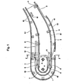
- Fig. 1 shows the guide device according to the invention based on the lower end of the stairs, how the step-shaped platforms are brought out of their inclined path into the horizontal path or vice versa and reverse their direction of movement.
- the following considerations apply mutatis mutandis to the sloping section and the top of the stairs, both of which are not shown here.
- Continuous escalators are usually driven by an upper sprocket, which sits on a motor-driven main shaft, and consist of a large number of stepped platforms, which are articulated on both sides. At the bottom of the stairs, the chain runs around idler sprockets 1, 2, which are often under the influence of a tension spring to maintain the chain tension, as is familiar to the person skilled in the escalator technology.
- both rail systems have main rails 3 for the chain rollers on the sides of the stairs, whereby in the area of the order Sweeping stations counter guides 4 are mounted. Trailing rails 5 are provided for the trailing rollers, which, however, only extend over the ends of the stairs in the lower run.
- the main rails 3.1 and the follower rails 5.1 are curved between the inclined sections and the horizontal sections in order to effect the step transition required here. In addition, the distance between the curved main rails 3.1 and trailing rails 5.1 changes constantly in this area in the upper run in order to ensure the gradual transition from platform to step - or vice versa depending on the direction of the step.
- the main rails are designed as channel-shaped guides 6 with a semicircular end part 7.
- the running rails 3, 5 in their various forms of construction are assembled without a device by means of rail holders 10, 11 and additional structural elements, with the carrier frame being manufactured on the basis of narrow tolerances Individual parts, the parallelism and the alignment of the running tracks are automatically guaranteed.
- two embodiments of the rail holder are required for the corresponding vertical and horizontal positioning of the rails: a rectangular rail holder 10 and an L-shaped rail holder 11.
- the rail holders thus act as central connecting elements between the support frame and the rails.
- the side plates 20 are initially to be screwed to the separately machined U-shaped cross member 21.
- the centering knobs 26, 27 on the rail holders 10, 11 are then brought into engagement with the corresponding centering openings 28, 29 in the side plates 20, thereby fixing the rail holders and side plates in their mutual position and connecting them to one another by means of the fastening means 30 in the fastening hole 31.
- the Spanniet 32 used here can be replaced by a screw or any other releasable or non-releasable connection means.
- the side plates 20 fulfill the double function as a precision template during assembly and as support elements for the rail holders.
- the rail holders 10, 11 each have a dovetail clamping device 35 on their rail support side 10.1, 11.1, which serves to clamp the running rails 3, 5 on all sides.
- the principle of device-less assembly is consistently continued when fastening the drawn counter-guides 4. The same are inserted into the rail holder 11 up to the stop 22 of the finger-shaped extension 23 and braced with it on the side plate 20.
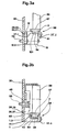
- FIG. 3a The assembly of the rail holder, side plate and running rail according to the invention is shown in detail in FIG. 3a for a rectangular rail holder 10 and in FIG. 3b for an L-shaped rail holder 11. "The following description of the connection construction applies in the same way to both types of rail holder.
- Both the rectangular and the L-shaped rail holder are provided on their fastening side 10.2, 11.2 with two centering knobs 26, 27 and have a dovetail clamping device 35 on the rail support side 10.1, 11.1.
- the fastening hole 48 serves to receive a fastening means for the construction of the rail holder on the side plate 20.
- the side plates 20 are provided in the area of the rail supports 10, 11 with centering openings 28, 29 which serve as reference points and, in cooperation with the centering knobs 26, 27 on the rail holders 10, 11, determine the parallelism and alignment of the running rails.
- the main and trailing rails 3, 5 have a dovetail-shaped profile 54 along their underside in order to be clamped in the dovetail clamping device 35, which has a fixed 35.1 and a movable jaw 35.2.
- the centering knobs 26, 27 on the rail holders 10, 11 are brought into engagement with the corresponding centering openings 28, 29 in the side plate 20, and the whole is connected by a rivet connection 55.
- the Spanniet was chosen for cost reasons, but is not intended to limit the invention in any way. A connection with a screw or other fastening means is also conceivable.
- the centering knobs 26, 27 In cooperation with the centering openings 28, 29, the centering knobs 26, 27 not only ensure the exact positioning of the rail holders on the side plate, but they also essentially take over the thrust forces that occur.
- the rivet or screw connection 55 only serves to absorb the tensile force resulting from the tilting moment.
- the dovetail clamping device 35 fixes the main and trailing rails 3, 5, on the running surfaces 57 of which the chain and drag rollers 58, 59 move, rigidly on all sides on the rail holders 10, 11.
- the dovetail profile 54 which extends along the entire length of the running rails 3, 5, ideally serves to hold the running rails rigidly but easily detachably on the rail supports by clamping. With a sufficient moment of inertia, the dovetail-shaped profile of the running rails enables a secure fastening of the running track, which ensures sufficient parallelism and alignment of the running rails even when the escalator is heavily loaded.
- bevels 56 are provided in the area of the rail runs and outflows in order to be able to better accommodate the running rails bent in the transition area from the horizontal part to the inclined part.
- the cant 61 is required if a force rivet 55 is used as the connecting means. With it, the span of the connection given by the side plate and the rail support should be adapted to the rivet used, since it is only commercially available in graded lengths.
- the width difference between the lower and the upper rail holder in the vicinity of the main and trailing rails is spanned with the intermediate plate 12. This measure makes it possible to meet all the requirements of escalator construction with only two types of rail holders, namely a rectangular and an L-shaped rail holder 10 and 11.
Abstract
Description
Die vorliegende Erfindung betrifft eine Führungseinrichtung für die Laufelemente von Endlosförderern wie Fahrtreppen und dergleichen, bei welchen Haupt- und Nachlaufschienen über Schienenhalter an einem Trägerrahmen befestigt sind.The present invention relates to a guide device for the running elements of endless conveyors such as escalators and the like, in which main and trailing rails are fastened to a carrier frame via rail holders.
Mit derartigen Führungseinrichtungen werden die Laufelemente längs ihrer endlosen Bahn gestützt und geführt, wobei ein möglichst geräuscharmer und erschütterungsfreier Lauf dieser Laufelemente erreicht werden soll. Bei Fahrtreppen dienen die Führungseinrichtungen auch dazu, die Trittfläche der als Treppenstufen ausgebildeten Laufelemente, beim Durchlaufen des oberen Trums, sowohl im horizontalen, als auch im ansteigenden Bereich und in den Übergängen horizontal zu führen.With such guide devices, the running elements are supported and guided along their endless path, with the aim of achieving a running of these running elements that is as quiet and vibration-free as possible. In the case of escalators, the guide devices also serve to horizontally guide the tread surface of the running elements designed as stair treads as they pass through the upper run, both in the horizontal and in the ascending area and in the transitions.
Es ist aus der DE-A-2 157 423 eine Fahrtreppenkonstruktion gemäss dem Oberbegriff des Patentanspruches 1 bekannt, bei der zum genauen Einstellen der Laufschienen spezielle Präzisionsschablonen verwendet werden. Diese Präzisionsschablonen enthalten Ausrichtelöcher und gewährleisten aufgrund einer entsprechenden maschinellen Bearbeitung Parallelität und Fluchtung der Laufschienen mit ausreichender Genauigkeit. Für den Zusammenbau werden die Schienenelemente mit den Schablonen in starrer gegenseitiger Zuordnung gehalten und mit denselben durch eine Präzisionsschweissung verbunden.It is known from DE-A-2 157 423 an escalator construction according to the preamble of claim 1, in which special precision templates are used for precise adjustment of the running rails. These precision stencils contain alignment holes and ensure parallelism and alignment of the running rails with sufficient accuracy due to appropriate machining. For assembly, the rail elements are held in rigid mutual association with the templates and connected to them by precision welding.
Solche Aufbauverfahren sind aufwendig und beinhalten die bekannten Nachteile der Schweisstechnologie: Zum einen ist der für das massgetreue Zusammenschweissen des Führungssystems notwendige Vorrichtungs- und Arbeitsaufwand erheblich, so dass nicht von einem zügigen und kostengünstigen Zusammenbau gesprochen werden kann. Zudem lässt sich trotz dieses beträchtlichen Aufwandes der Gleichlauf der Laufelemente nicht im notwendigen Ausmass sicherstellen. Dies deshalb, weil selbst beim Präzisionsschweissen durch das Einbringen von Wärme Verzug in der Konstruktion entsteht, was durch nachfolgendes Kalt- und Warmrichten nur zum Teil behoben werden kann.Such assembly processes are complex and include the known disadvantages of welding technology: On the one hand, the device and work required for the true-to-size welding of the guide system is considerable, so that one cannot speak of a quick and inexpensive assembly. In addition, despite this considerable effort, the synchronism of the running elements cannot be ensured to the necessary extent. This is because even with precision welding, the introduction of heat causes warpage in the construction, which can only be partially remedied by subsequent cold and hot straightening.
Ferner werden bei derartigen Aufbaukonzepten anlagebezogene Konstruktionselemente verschiedenster Ausbildung und Abmessung benötigt. Der Einsatz von in grossen Serien gefertigten Einzelteilen, die für einen weiten Bereich von Anlagen in Form von gleichartigen Normteilen verwendet werden können, ist allgemein nicht möglich.In addition, system-related construction elements of the most varied design and dimensions are required in such construction concepts. The use of individual parts manufactured in large series, which can be used for a wide range of systems in the form of similar standard parts, is generally not possible.
Im weiteren sind bei einer Schweisskonstruktion die der Abnützung unterworfenen Laufschienen im allgemeinen schwer lösbar oder sogar unlösbar mit dem Trägerrahmen verbunden, so dass keine Möglichkeit besteht, dieselben - unabhängig vom Trägerrahmen - einer Oberflächenbehandlung zu unterziehen oder sie, bei erhöhtem Verschleiss, rasch und leicht auszuwechseln.Furthermore, in the case of a welded construction, the running tracks subject to wear are generally connected to the support frame in a manner which is difficult to detach or even inseparable, so that there is no possibility of subjecting them to a surface treatment, regardless of the support frame, or of rapidly and easily replacing them if there is increased wear .
Hier will die Erfindung Abhilfe schaffen. Die Erfindung, wie sie in den Ansprüchen gekennzeichnet ist, löst die Aufgabe, eine Führungseinrichtung für Endlosförderer wie Fahrtreppen und dergleichen zu schaffen, die sich mit geringem Aufwand und ohne Vorrichtung auf der Baustelle mit grosser Genauigkeit zusammenbauen lässt und deren Laufschinen leicht ausgebaut und ersetzt werden können. Die Neuerung bezweckt ferner die Schaffung einer Führungseinrichtung, die aus wenigen, in grossen Serien gefertigten Normteilen aufgebaut werden kann und bei der die Lagerhaltung vereinfacht sowie die Herstellung verbilligt ist.The invention seeks to remedy this. The invention, as characterized in the claims, solves the problem of creating a guide device for endless conveyors such as escalators and the like, which can be assembled with great effort and without any device on the construction site with great accuracy and whose running rails can be easily removed and replaced can. The innovation also aims to create a guiding device that can be constructed from a few standard parts that are manufactured in large series and that simplifies storage and makes production cheaper.
Diese Aufgabe wird erfindungsgemäss dadurch gelöst, dass der die Haupt- und Nachlaufschiene tragende Schienenhalter an seiner mit mindestens einem ein Befestigungsmittel aufnehmenden Befestigungsloch versehenen Befestigungsseite mindestens zwei in entsprechende Zentrieröffnungen eines am Trägerrahmen befestigten Seitenschildes eingreifende Zentriernoppen aufweist und an seiner rechtwinklig zur Befestigungsseite stehenden Schienenauflageseite eine Schwalbenschwanzklemmvorrichtung zur Aufnahme der im Profil schwalbenschwanzförmig ausgebildeten Schienenunterseite besitzt, wobei die Schwalbenschwanzklemmvorrichtung aus einer am Schienenhalter angeordneten festen Klemmbacke und einer mittels Schwalbenschwanzverbindung am Schienenhalter befestigbar beweglichen Klemmbacke besteht.This object is achieved according to the invention in that the rail holder carrying the main and trailing rail has at least two centering knobs engaging in corresponding centering openings of a side plate fastened to the support frame on its fastening side provided with at least one fastening hole receiving fastening means and a dovetail clamping device on its rail support side which is perpendicular to the fastening side for accommodating the underside of the rail, which is designed in the shape of a dovetail, the dovetail clamping device consisting of a fixed jaw arranged on the rail holder and a movable jaw which can be fastened to the rail holder by means of a dovetail connection.
Gemäss einer bevorzugten Ausführungsform sind die Zentriernoppen, sowie das Befestigungsloch am Schienenhalter hinsichtlich der senkrecht zur Befestigungs- und Schienenauflageseite stehenden Schienenhalter-Mittelebene spiegelsymmetrisch angeordnet.According to a preferred embodiment, the centering knobs and the fastening hole on the rail holder are arranged in mirror symmetry with respect to the middle of the rail holder that is perpendicular to the fastening and rail support side.
Um das Befestigen der im Übergangsbereich gekrümmt ausgebildeten Laufschinenen zu erleichtern, sind nach einer Weiterbildung der Erfindung, bei den Schwalbenschwanzklemmvorrichtungen die Schienenauflagen im Bereich der An- und Abläufe der Laufschienen angeschrägt.In order to facilitate the fastening of the running rails which are curved in the transition area, according to a development of the invention, the rail supports in the dovetail clamping devices are chamfered in the area of the run-in and running-out of the running rails.
Weiterhin ist für eine kostengünstige Fabrikation vorgesehen, die Schienenhalter im Druckgussverfahren herzustellen und die Zentriernoppen als masshaltige Angüsse auszubilden.Furthermore, for cost-effective production, it is intended to manufacture the rail holders using the die-casting process and to design the centering knobs as dimensionally accurate sprues.
Gemäss einer weiteren bevorzugten Ausführungsform weist der Schienenhalter in der Schienenhalter-Mittelebene entweder eine rechteckförmige oder eine L-förmige Schnittfläche auf.According to a further preferred embodiment, the rail holder has either a rectangular or an L-shaped cutting surface in the central plane of the rail holder.
Weiterhin ist der L-förmige Schienenhalter mit einer fingerförmigen Verlängerung ausgerüstet, um die Gegenführungen zwischen seiner Längsseite und dem Seitenschild zu verspannen.Furthermore, the L-shaped rail holder is equipped with a finger-shaped extension to brace the mating guides between its long side and the side plate.
Durch diese Massnahmen wird nicht nur die der Erfindung zugrundeliegende Aufgabe vorteilhaft gelöst, sondern es wird darüber hinaus eine Führungseinrichtung geschaffen, die folgende Vorteile bietet:
- Die Führungseinrichtung wird unter Ausrichtung aller kritischen Einzelbauteile auf die optimale Positionierung und Befestigung der Laufbahnen gefertigt, so dass sich der Aufbau mit geringem Aufwand und ohne Vorrichtung bewerkstelligen lässt. Es ist also weder die Errichtung eines teuren Montagegerüstes, noch viel Platz zum Lagern von Bauteilen erforderlich.
- The guide device is manufactured with the alignment of all critical individual components for the optimal positioning and fastening of the raceways, so that the structure can be accomplished with little effort and without any device. It is therefore neither necessary to erect an expensive assembly scaffold nor to store a lot of space for components.
Ein weiterer Vorteil der Erfindung kann darin gesehen werden, dass für die Genauigkeit der Stufenführung - und damit für den ruhigen Lauf einer Rolltreppe - nur dafür Sorge zu tragen ist, dass die Steckverbindung Zentriernoppen/Zentrieröffnung masshaltig ist und dass bei deren Fertigung die engen Toleranzen eingehalten werden. Dies dürfte aber leicht und kostengünstig möglich sein, da die Fertigung der einzelnen Konstruktionsteile in der Werkstatt erfolgt, wo bessere maschinelle Einrichtungen zur Verfügung stehen als auf einer Baustelle. Diesbezüglich ist vorgesehen, für die Bearbeitung der Seitenschilder und insbesondere für das Anbringen der Zentrieröffnungen eine NC-Maschine zu verwenden. Damit können alle wesentlichen Einflussfaktoren, welche den Lauf einer Rolltreppe bestimmen, mit ausreichender Genauigkeit gewährleistet werden.Another advantage of the invention can be seen in the fact that for the accuracy of the step guidance - and thus for the smooth running of an escalator - only care must be taken that the plug connection centering knobs / centering opening is true to size and that the narrow tolerances are adhered to during their manufacture. However, this should be possible easily and inexpensively, since the individual construction parts are manufactured in the workshop, where better mechanical facilities are available than on a construction site. In this regard, it is intended to use an NC machine for processing the side plates and in particular for making the centering openings. This means that all essential influencing factors that determine the running of an escalator can be guaranteed with sufficient accuracy.
Da der für einen ruhigen Treppenlauf erforderliche Gleichlauf der Laufelemente durch das Zusammenspiel von Zentriernoppen und Zentrieröffnungen ausreichend gewährleistet ist, ist es nicht mehr notwendig, die Laufschienen nach dem Einbau auszurichten und dimensionsmässig einzustellen. Auf die Verstellbarkeit von Verbindungen innerhalb eines Schienenblockes kann deshalb verzichtet werden.Since the synchronism of the running elements required for a smooth staircase run is sufficiently ensured by the interaction of centering knobs and centering openings, it is no longer necessary to align the running rails after installation and to adjust their dimensions. The adjustability of connections within a rail block can therefore be dispensed with.
Aufgrund des vorrichtungslosen und einfachen Zusammenbaues ohne nachfolgendes Einstellen der Laufschienen eignet sich die erfindungsgemässe Führungseinrichtung vortrefflich zum Zusammenbau an Ort und Stelle, wo wegen baulicher oder anderer Erschwernisse oft unter schwierigen Bedingungen gearbeitet werden muss. Allfällige Unzulänglichkeiten in der Arbeitsausführung können sich so nicht nachteilig auf den Gleichlauf der Laufelemente auswirken, da die Genauigkeit der Stufenführung durch die vorfabrizierten und mit engen Toleranzen gefertigten Einzelteile bestimmt wird.Because of the device-free and simple assembly without subsequent adjustment of the running rails, the guide device according to the invention is excellently suitable for assembly on the spot where work often has to be carried out under difficult conditions due to structural or other difficulties. Any shortcomings in the execution of the work cannot have a detrimental effect on the synchronism of the running elements, since the accuracy of the step guidance is determined by the prefabricated individual parts manufactured with tight tolerances.
Darüber hinaus sind die bausteinartigen Montageelemente nach der Erfindung so ausgebildet, dass sie sich an Ort und Stelle leicht montieren als auch wieder leicht demontieren lassen und ein verhältnismässig geringes Gewicht aufweisen. So können z.B. die der Abnützung unterworfenen Laufschienen zwecks Wartung oder Ersatz durch Lösen der Schwalbenschwanzklemmung leicht ausgebaut und vorrichtungslos wieder montiert werden.In addition, the modular assembly elements according to the invention are designed in such a way that they can be easily assembled on site as well as easily disassembled and have a relatively low weight. For example, the tracks subject to wear can be easily removed for maintenance or replacement by loosening the dovetail clamp and reassembled without a device.
Durch die leichte Auswechselbarkeit der Bauteile wird die Instandhaltung von Endlosförderern wie Rolltreppen, sowie die entsprechende Ausbildung des Wartungspersonals stark vereinfacht.Due to the easy interchangeability of the components, the maintenance of endless conveyors such as escalators, as well as the corresponding training of the maintenance personnel is greatly simplified.
Die wesentlichen Elemente des erfindungsgemässen Aufbaukonzeptes, nämlich die Schienenhalter, die Gegenführung, die Niet- und Schraubverbindungen sowie die Schwalbenschwanzklemmvorrichtung sind funktions- und nicht anlagebezogen, also unabhängig von einer Anlage in der gleichen Ausführung immer wieder eihsetzbar. Die Anpassung für den einzelnen Anwendungsfall erfolgt über die Seitenschilder bzw. durch die Positionierung der entsprechenden Zentrieröffnungen.The essential elements of the construction concept according to the invention, namely the rail holder, the counter-guide, the rivet and screw connections and the dovetail clamping device are function-related and not system-related, that is, they can be used again and again independently of a system in the same design. The adaptation for the individual application takes place via the side plates or by positioning the corresponding centering openings.
Hinsichtlich der Konstruktionselemente wie der Verbindungstechnik kann deshalb von einem bausteinartigen Aufbau gesprochen werden. Für eine grosse Variantenzahl von Anlagen, wie z.B. für die Standardbreiten 80 cm und 110 cm, können die gleichen in Normgrössen serienmässig hergestellten Einzelteile verwendet werden, die sich durch leichte Handhabbarkeit und Vielfalt der Einsatzmöglichkeiten auszeichnen.With regard to the construction elements such as the connection technology, one can therefore speak of a modular structure. For a large number of systems, such as For the standard widths of 80 cm and 110 cm, the same individual parts can be used, which are produced in standard sizes and which are characterized by easy handling and variety of possible uses.
Daraus ergibt sich der Vorteil einer einfachen Fertigung und einer unkomplizierten Disposition des Materialbedarfs.This results in the advantage of simple production and uncomplicated disposition of the material requirements.
Daraus resultiert eine erhebliche Verbilligung und Platzersparnis auf der Baustelle selbst, weil sich die dort zu leistenden Arbeiten vereinfachen und weder die Errichtung eines teuren Montagegerüstes noch viel Platz zum Lagern von Bauteilen erforderlich ist.This results in a significant reduction in costs and space savings on the construction site itself, because the work to be done there is simplified and neither the erection of expensive assembly scaffolding nor much space for storing components is required.
Es ist offensichtlich, dass die mit der Erfindung erzielten Verbesserungen wie vorrichtungsloser Zusammenbau, bausteinartiger Aufbau, leichte Auswechselbarkeit der Laufschienen usw. auch wirtschaftliche Vorteile bieten: die Herstellung der Fahrtreppen wird verbilligt, die Kosten für deren Montage und Unterhalt merklich gesenkt und so allgemein eine kostengünstige Lösung erzielt.It is obvious that the improvements achieved with the invention, such as device-less assembly, modular structure, easy interchangeability of the running tracks, etc., also offer economic advantages: the manufacture of the escalators is cheaper, the costs for their installation and maintenance are significantly reduced, and thus generally inexpensive Solution achieved.
Die Erfindung wird nachstehend in ihrer Anwendung bei einer Rolltreppe beschrieben, jedoch ist das hier zugrundeliegende Prinzip in gleicher Weise entsprechend auch für andere Führungseinrichtungen verwendbar.The invention is described below in its application in an escalator, however the principle on which it is based can be used in the same way for other guide devices.
Die lediglich einen Ausführungsweg darstellenden Zeichnungen zeigen:
- Fig. 1 einen Vertikalschnitt des den unteren Abschluss einer Rolltreppe bildenden unteren Schienenblockes längs der Linie HH in Fig. 2 in Richtung der angegebenen Pfeile gesehen,
- Fig. 2 einen Vertikalschnitt des den unteren Abschluss einer Rolltreppe bildenden unteren Schienenblockes längs der Linie FF in Fig. 1 in Richtung der angegebenen Pfeile gesehen. Wegen der Symmetrie der Konstruktion ist nur die rechte Hälfte des Vertikalschnittes bezeichnet,
- Fig. 3a eine Konstruktionseinheit im Vertikalschnitt bestehend aus einem rechteckförmigen Schienenhalter mit festgeklemmter Laufschiene, der an einem Seitenschild angebaut ist,
- Fig. 3b eine Konstruktionseinheit im Vertikalschnitt bestehend aus einem L-förmigen Schienenhalter mit festgeklemmter Laufschiene, der an einem Seitenschild angebaut ist.
- 1 shows a vertical section of the lower rail block forming the lower end of an escalator along the line HH in FIG. 2 in the direction of the arrows indicated,
- Fig. 2 is seen a vertical section of the lower rail block forming the lower end of an escalator along the line FF in Fig. 1 in the direction of the arrows indicated. Because of the symmetry of the construction, only the right half of the vertical section is labeled,
- 3a shows a construction unit in vertical section consisting of a rectangular rail holder with a clamped running rail, which is attached to a side plate,
- Fig. 3b is a construction unit in vertical section consisting of an L-shaped rail holder with a clamped running rail, which is attached to a side plate.
Fig. 1 zeigt die erfindungsgemässe Führungseinrichtung anhand des unteren Treppenendes, wie die stufenförmigen Plattformen aus ihrer geneigten Bahn in die horizontale Bahn gebracht werden oder umgekehrt und ihre Bewegungsrichtung umkehren. Die folgenden Überlegungen gelten sinngemäss aber auch für die Schrägstrecke und das obere Treppenende, die beide hier nicht gezeigt sind.Fig. 1 shows the guide device according to the invention based on the lower end of the stairs, how the step-shaped platforms are brought out of their inclined path into the horizontal path or vice versa and reverse their direction of movement. The following considerations apply mutatis mutandis to the sloping section and the top of the stairs, both of which are not shown here.
Kontinuierliche Fahrtreppen werden üblicherweise von einem oberen Kettenrad angetrieben, das auf einer motorgetriebenen Hauptwelle sitzt und bestehen aus einer Vielzahl stufenförmiger Plattformen, die an ihren beiden Seiten untereinander gelenkig verbunden sind. Am unteren Treppenende läuft die Kette um Leerlaufkettenräder 1, 2, die zur Erhaltung der Kettenspannung oft unter dem Einfluss einer Spannfeder stehen, wie das dem auf dem Gebiet der Rolltreppentechnik tätigen Fachmann geläufig ist.Continuous escalators are usually driven by an upper sprocket, which sits on a motor-driven main shaft, and consist of a large number of stepped platforms, which are articulated on both sides. At the bottom of the stairs, the chain runs around idler sprockets 1, 2, which are often under the influence of a tension spring to maintain the chain tension, as is familiar to the person skilled in the escalator technology.
Um die Plattform auf ihrer endlosen Bahn zu stützen und zu führen, ist für das obere, die Last tragende Trum als auch für das untere rücklaufende Trum je ein Schienensystem vorhanden. Beide Schienensysteme besitzen auf den Treppenseiten Hauptschienen 3 für die Kettenrollen, wobei im Bereich der Umkehrstationen Gegenführungen 4 montiert sind. Für die Nachlaufrollen sind Nachlaufschienen 5 vorgesehen, die sich im unteren Trum allerdings nur über die Treppenenden erstrecken. Zwischen den Schrägstrecken und den Horizontalstrecken sind die Hauptschienen 3.1 und die Nachlaufschienen 5.1 gekrümmt ausgebildet, um den hier notwendigen Stufenübergang zu bewirken. Zudem ändert sich in diesem Bereich beim oberen Trum der Abstand zwischen den gekrümmten Hauptschienen 3.1 und Nachlaufschienen 5.1 stetig, um den allmählichen Übergang vom Plattform- zum Stufengebildet - oder umgekehrt je nach Stufenlaufrichtung - zu gewährleisten.In order to support and guide the platform on its endless path, there is a rail system for the upper, load-bearing strand and for the lower returning strand. Both rail systems have
Im unteren und auch - im hier nicht dargestellten - oberen Treppenende, wo die Treppenstufen ihre Bewegungsrichtung umkehren, sind die Hauptschienen als kanalförmige Führungen 6 mit halbkreisförmigem Endteil 7 ausgebildet.In the lower and also - in the upper stair end, not shown here, where the stair steps reverse their direction of movement, the main rails are designed as channel-shaped guides 6 with a semicircular end part 7.
Aufgrund der erfindungsgemässen Führungseinrichtung, die mit Bezug auf die Figuren 2 und 3 später eingehend erläutert wird, werden die Laufschienen 3, 5 in ihren verschiedenen Ausbildungsformen durch Schienenhalter 10, 11 und zusätzliche Aufbauelemente vorrichtungslos mit dem Trägerrahmen zusammengebaut, wobei aufgrund der mit engen Toleranzen gefertigten Einzelteile die Parallelität und die Fluchtung der Laufschienen automatisch gewährleistet sind. Für die entsprechende vertikale und horizontale Positionierung der Laufschienen sind allerdings zwei Ausführungsformen des Schienenhalters erforderlich: ein rechteckiger Schienenhalter 10, sowie ein L-förmiger Schienenhalter 11. Als Teil der Führungseinrichtung wirken die Schienenhalter also als zentrale Verbindungselemente zwischen dem Trägerrahmen und den Laufschienen.On account of the guide device according to the invention, which will be explained in detail later with reference to FIGS. 2 and 3, the running
Die sich aus der Annäherung von Haupt- und Nachlaufschienen im oberen Trum ergebende Breitendifferenz zwischen den entsprechenden Schienenhaltern wird mit Zwischenblechen 12 ausgeglichen.The difference in width between the corresponding rail holders resulting from the approximation of the main and trailing rails in the upper run is compensated with
Die Fig. 2 zeigt schematisch das erfindungsgemässe Aufbaukonzept der Führungseinrichtung am Beispiel des unteren Schienenblockes. Wegen der Symmetrie der Konstruktion ist nur deren rechte Hälfte bezeichnet; die Beschreibung gilt aber sinngemäss entsprechend auch für die linke Hälfte des Schnittes FF.2 schematically shows the construction concept of the guide device according to the invention using the example of the lower rail block. Because of the symmetry of the construction, only the right half is marked; however, the description applies correspondingly to the left half of the section FF.
Für den vorrichtungslosen Aufbau des unteren Schienenblockes sind vorerst die Seitenschilder 20 mit dem separat bearbeiteten U-profilförmigen Querträger 21 zu verschrauben. Alsdann werden die Zentriernoppen 26, 27 an den Schienenhaltern 10, 11 mit den entsprechenden Zentrieröffnungen 28, 29 in den Seitenschildern 20 zum Eingriff gebracht und dadurch Schienenhalter und Seitenschilder in ihrer gegenseitigen Lage fixiert und mittels des Befestigungsmittels 30 im Befestigungsloch 31 miteinander verbunden. Der hier verwendete Spanniet 32 kann durch eine Schraube oder jedes andere lösbare bzw. nicht lösbare Verbindungsmittel ersetzt werden.For the device-free construction of the lower rail block, the
Als Teil der erfindungsgemässen Führungseinrichtung erfüllen die Seitenschilder 20 die Doppelfunktion als Präzisionsschablone während der Montage und als Stützelemente für die Schienenhalter.As part of the guide device according to the invention, the
Das Aufbaukonzept, das wesentliches Merkmal der vorliegenden Erfindung ist, wird anhand der Fig. 3 im Detail erläutert.The construction concept, which is an essential feature of the present invention, is explained in detail with reference to FIG. 3.
Die Schienenhalter 10, 11 besitzen auf ihrer Schienenauflageseite 10.1, 11.1 je eine Schwalbenschwanzklemmvorrichtung 35, die zum allseitigen Festklemmen der Laufschienen 3, 5 dient.The
Bei der Führung der Laufschienen über die volle Länge einer Fahrtreppe ergeben sich für die einzelnen Bereiche und auch für das obere und untere Trum Unterschiede in den vertikalen Abständen zwischen den Laufschienen und dem Trägerrahmen, die überbrückt werden müssen. Ein erster grobstufiger Ausgleich erfolgt durch die Wahl des Schienenhalters, je nachdem, ob er in der rechteckförmigen oder L-förmigen Version verwendet wird. Die beiden Versionen unterscheidensich nämlich auch im Abstand zwischen der Längsachse des Befestigungsloches und der Schienenauflagefläche, wobei die entsprechenden Werte 5 cm für den rechteckförmigen Schienenhalter 10 und 10 cm für den L-förmigen Schienenhalter 11 betragen. Eine allenfalls noch verbleibende Restdistanz wird durch entsprechende Positionierung des Schienenhalters auf dem Seitenschild feinstufig ausgeglichen. Der rechteckförmige sowie der L-förmige Schienenhalter sind in Fig. 3 näher erläutert.When guiding the running rails over the full length of an escalator, there are differences in the vertical distances between the running rails and the support frame for the individual areas and also for the upper and lower run, which must be bridged. A first coarse adjustment is made by choosing the rail holder, depending on whether it is used in the rectangular or L-shaped version. The two versions also differ in the distance between the longitudinal axis of the fastening hole and the rail support surface, the corresponding values being 5 cm for the
Das Prinzip des vorrichtungslosen Zusammenbaues wird bei der Befestigung der gezogenen Gegenführungen 4 konsequent fortgesetzt. Dieselben werden bis zum Anschlag 22 der fingerförmigen Verlängerung 23 in den Schienenhalter 11 eingelegt und mit ihm am Seitenschild 20 verspannt.The principle of device-less assembly is consistently continued when fastening the drawn
Der erfindungsgemässe Zusammenbau von Schienenhalter, Seitenschild und Laufschiene ist detailliert in Fig. 3a für einen rechteckförmigen Schienenhalter 10 und in Fig. 3b für einen L-förmigen Schienenhalter 11 gezeigt. "Die nachfolgende Beschreibung der Verbindungskonstruktion gilt in gleicher Weise für beide Arten von Schienenhalter.The assembly of the rail holder, side plate and running rail according to the invention is shown in detail in FIG. 3a for a
Sowohl der rechteckförmige als auch der L-förmige Schienenhalter sind auf ihrer Befestigungsseite 10.2, 11.2 mit je zwei Zentriernoppen 26, 27 versehen und weisen auf der Schienenauflageseite 10.1, 11.1 eine Schwalbenschwanzklemmvorrichtung 35 auf. Das Befestigungsloch 48 dient zur Aufnahme eines Befestigungsmittels für den Aufbau des Schienenhalters an das Seitenschild 20. Im Hinblick auf eine preisgünstige Fertigung werden die Schienenhalter im Druckgussverfahren hergestellt, so dass die Zentriernoppen 26, 27 masshaltig und mit den erforderlichen Toleranzen als Angüsse ausgebildet werden können.Both the rectangular and the L-shaped rail holder are provided on their fastening side 10.2, 11.2 with two centering knobs 26, 27 and have a
Die Seitenschilder 20 sind im Bereich der Schienenträger 10, 11 mit Zentrieröffnungen 28, 29 versehen, die als Referenzpunkte dienen und im Zusammenwirken mit den Zentriernoppen 26, 27 auf den Schienenhaltern 10, 11 die Parallelität und Fluchtung der Laufschienen bestimmen.The
Die Haupt- und Nachlaufschienen 3, 5 weisen längs ihrer Unterseite ein schwalbenschwanzförmiges Profil 54 auf, um in der Schwalbenschwanzklemmvorrichtung 35, die eine feste 35.1 und eine bewegliche Klemmbacke 35.2 aufweist, festgeklemmt zu werden.The main and trailing
Für den Zusammenbau werden die Zentriernoppen 26, 27 auf den Schienenhaltern 10, 11 mit den entsprechenden Zentrieröffnungen 28, 29 im Seitenschild 20 zum Eingriff gebracht, und das Ganze durch eine Nietverbindung 55 verbunden. Der Spanniet wurde aus Kostengründen gewählt, soll aber die Erfindung in keiner Weise beschränken. Eine Verbindung mit einer Schraube oder einem anderen Befestigungsmittel ist ebenfalls denkbar.For assembly, the centering knobs 26, 27 on the
Durch die sehr präzise Anordnung der Zentrieröffnungen 28, 29 in den Seitenschildern 20 sowie der Zentriernoppen 26, 27 auf den Schienenhaltern 10, 11 sind dieselben automatisch so positioniert, dass die mittels Schwalbenschwanzklemmung mit ihnen starr verbundenen Laufschienen 3, 5 hinsichtlich Parallelität und Fluchtung den Anforderungen für einen ruhigen Treppenlauf genügen.Due to the very precise arrangement of the centering openings 28, 29 in the
Im Zusammenwirken mit den Zentrieröffnungen 28, 29 gewährleisten die Zentriernoppen 26, 27 nicht nur die exakte Positionierung der Schienenhalter am Seitenschild, sondern sie übernehmen im wesentlichen auch die auftretenden Schubkräfte. Die Niet- oder Schraubenverbindung 55 dient lediglich dazu, die sich aus dem Kippmoment ergebende Zugkraft aufzunehmen.In cooperation with the centering openings 28, 29, the centering knobs 26, 27 not only ensure the exact positioning of the rail holders on the side plate, but they also essentially take over the thrust forces that occur. The rivet or screw
Durch die Schwalbenschwanzklemmvorrichtung 35 sind die Haupt- und Nachlaufschienen 3, 5, auf deren Laufflächen 57 sich die Ketten- und Schlepprollen 58, 59 bewegen, allseitig und starr auf den Schienenhaltern 10, 11 befestigt.The
Das Schwalbenschwanzprofil 54, das sich unten an den Laufschienen 3, 5 über deren ganze Länge hinzieht, dient in idealer Weise dazu, durch Klemmung die Laufschienen starr aber leichtlösbar auf den Schienenträgern festzuhalten. Das schwalbenschwanzförmige Profil der Laufschienen ermöglicht bei genügendem Flächenträgheitsmoment eine sichere Laufbahnbefestigung, die auch bei schwerer Belastung der Fahrtreppe ausreichende Parallelität und Fluchtung der Laufschienen gewährleistet.The
Um bei der Schwalbenschwanzklemmvorrichtung 35 eine Doppelpassung zu vermeiden, ist zwischen der Laufschiene 3 und dem Schienenhalter 11 ein ausreichendes Spiel 60 eingehalten.In order to avoid a double fit in the
Ebenso sind im Bereich der Schienenauf- und -abläufe Anschrägungen 56 angebracht, um die im Übergangsbereich vom Horizontalteil zum geneigten Teil gebogenen Laufschienen besser aufnehmen zu können.Likewise, bevels 56 are provided in the area of the rail runs and outflows in order to be able to better accommodate the running rails bent in the transition area from the horizontal part to the inclined part.
Die Überhöhung 61 ist erforderlich, wenn als Verbindungsmittel ein Kraftniet 55 verwendet wird. Mit ihr soll die durch das Seitenschild und den Schienenträger gegebene Spannweite der Verbindung an den verwendeten Kraftniet angepasst werden, da er im Handel nur in abgestuften Längen erhältlich ist.The
Die im Annäherungsbereich der Haupt- und Nachlaufschienen vorhandene Breitendifferenz vom unteren zum oberen Schienenhalter wird mit dem Zwischenblech 12 überspannt. Durch diese Massnahme ist es möglich, mit nur zwei Arten von Schienenhaltern, nämlich einem rechteckförmigen und einem L-förmigen Schienenhalter 10 und 11 allen Erfordernissen des Fahrtreppenbaues zu genügen.The width difference between the lower and the upper rail holder in the vicinity of the main and trailing rails is spanned with the
Claims (7)
Priority Applications (1)
| Application Number | Priority Date | Filing Date | Title |
|---|---|---|---|
| AT81108919T ATE10926T1 (en) | 1980-12-23 | 1981-10-26 | GUIDE DEVICE FOR THE RUNNING ELEMENTS OF ENDLESS CONVEYOR SUCH AS ESCALATORS AND THE LIKE. |
Applications Claiming Priority (2)
| Application Number | Priority Date | Filing Date | Title |
|---|---|---|---|
| CH9514/80 | 1980-12-23 | ||
| CH9514/80A CH648811A5 (en) | 1980-12-23 | 1980-12-23 | GUIDE DEVICE FOR THE RUNNING ELEMENTS OF CONTINUOUSLY CONVEYORS, ESPECIALLY ESCALATORS. |
Publications (2)
| Publication Number | Publication Date |
|---|---|
| EP0054687A1 EP0054687A1 (en) | 1982-06-30 |
| EP0054687B1 true EP0054687B1 (en) | 1984-12-27 |
Family
ID=4352795
Family Applications (1)
| Application Number | Title | Priority Date | Filing Date |
|---|---|---|---|
| EP81108919A Expired EP0054687B1 (en) | 1980-12-23 | 1981-10-26 | Guiding device for carrying surfaces of endless belt conveyors such as escalators and the like |
Country Status (8)
| Country | Link |
|---|---|
| US (1) | US4484674A (en) |
| EP (1) | EP0054687B1 (en) |
| AT (1) | ATE10926T1 (en) |
| CH (1) | CH648811A5 (en) |
| DE (1) | DE3167978D1 (en) |
| ES (1) | ES8304880A1 (en) |
| FI (1) | FI68594C (en) |
| GB (1) | GB2089753B (en) |
Cited By (1)
| Publication number | Priority date | Publication date | Assignee | Title |
|---|---|---|---|---|
| US11066275B2 (en) | 2019-01-23 | 2021-07-20 | Otis Elevator Company | Conveyance belt for a conveyor |
Families Citing this family (13)
| Publication number | Priority date | Publication date | Assignee | Title |
|---|---|---|---|---|
| US4662502A (en) * | 1983-10-12 | 1987-05-05 | Mitsubishi Denki Kabushiki Kaisha | Curved escalator |
| DE3635879C1 (en) * | 1986-10-22 | 1988-02-11 | Uwe Kochanneck | Workplace |
| DE3742309A1 (en) * | 1987-12-14 | 1989-06-29 | Orenstein & Koppel Ag | RUNNING PROFILE FOR THE ROLLS OF A TREADMILL |
| US4961492A (en) * | 1988-07-22 | 1990-10-09 | Simplimatic Engineering Company | Article carrying conveyor and wearstrip set therefor |
| SE516848C2 (en) * | 2000-07-05 | 2002-03-12 | Flexlink Components Ab | Switching device for conveyor |
| JP4292104B2 (en) * | 2004-05-06 | 2009-07-08 | 株式会社日立製作所 | Passenger conveyor |
| ES2299408B1 (en) * | 2007-10-18 | 2009-06-12 | Thyssenkrupp Elevator (Es/Pbb) Ltd. | SELF-SUPPORTING GUIDE SYSTEM FOR ROLLING CORRIDORS. |
| CN101239688B (en) * | 2008-03-14 | 2011-01-12 | 浙江西子重工机械有限公司 | Arm rest lift side sheet and its processing method |
| EP2433893A1 (en) * | 2010-09-24 | 2012-03-28 | Inventio AG | Passenger transport device |
| DE112015006581B4 (en) * | 2015-06-03 | 2019-10-10 | Mitsubishi Electric Corporation | Stages passage adjustment device for a passenger conveyor |
| DE102017130730A1 (en) * | 2017-12-20 | 2019-06-27 | Thyssenkrupp Ag | Bypass for external roller chains of a passenger transport device |
| DE102018213647A1 (en) * | 2018-08-14 | 2019-08-01 | Thyssenkrupp Ag | Guide rail holding system for an escalator |
| US20230416056A1 (en) * | 2020-12-21 | 2023-12-28 | Inventio Ag | Rail fastening device for guide rail sections of an escalator or moving walkway |
Family Cites Families (8)
| Publication number | Priority date | Publication date | Assignee | Title |
|---|---|---|---|---|
| US1958162A (en) * | 1930-03-15 | 1934-05-08 | West Virginia Rail Company | Track construction |
| US1956155A (en) * | 1932-09-22 | 1934-04-24 | Otis Elevator Co | Moving stairway |
| US2686585A (en) * | 1949-05-04 | 1954-08-17 | Otis Elevator Co | Moving stairway |
| US2936872A (en) * | 1957-05-24 | 1960-05-17 | Rheinstahl Hamburg Stahlbau Eg | Moving stairways |
| US3707220A (en) * | 1970-11-23 | 1972-12-26 | Westinghouse Electric Corp | Modular passenger conveyor construction |
| US3834513A (en) * | 1971-12-20 | 1974-09-10 | Hitachi Ltd | Guide rail means |
| US4046248A (en) * | 1974-01-15 | 1977-09-06 | Chemcut Corporation | Connecting and alignment means for modular chemical treatment system |
| AT330655B (en) * | 1974-11-15 | 1976-07-12 | Wertheim Werke Ag | STRUCTURAL STRUCTURE, IN PARTICULAR FOR ESCALATORS OR DGL. |
-
1980
- 1980-12-23 CH CH9514/80A patent/CH648811A5/en not_active IP Right Cessation
-
1981
- 1981-10-22 GB GB8131931A patent/GB2089753B/en not_active Expired
- 1981-10-26 EP EP81108919A patent/EP0054687B1/en not_active Expired
- 1981-10-26 AT AT81108919T patent/ATE10926T1/en not_active IP Right Cessation
- 1981-10-26 DE DE8181108919T patent/DE3167978D1/en not_active Expired
- 1981-11-13 FI FI813602A patent/FI68594C/en not_active IP Right Cessation
- 1981-11-30 US US06/325,929 patent/US4484674A/en not_active Expired - Lifetime
- 1981-12-23 ES ES508329A patent/ES8304880A1/en not_active Expired
Cited By (1)
| Publication number | Priority date | Publication date | Assignee | Title |
|---|---|---|---|---|
| US11066275B2 (en) | 2019-01-23 | 2021-07-20 | Otis Elevator Company | Conveyance belt for a conveyor |
Also Published As
| Publication number | Publication date |
|---|---|
| DE3167978D1 (en) | 1985-02-07 |
| ATE10926T1 (en) | 1985-01-15 |
| CH648811A5 (en) | 1985-04-15 |
| EP0054687A1 (en) | 1982-06-30 |
| ES508329A0 (en) | 1983-04-01 |
| ES8304880A1 (en) | 1983-04-01 |
| FI813602L (en) | 1982-06-24 |
| US4484674A (en) | 1984-11-27 |
| GB2089753B (en) | 1984-07-18 |
| GB2089753A (en) | 1982-06-30 |
| FI68594B (en) | 1985-06-28 |
| FI68594C (en) | 1985-10-10 |
Similar Documents
| Publication | Publication Date | Title |
|---|---|---|
| EP0054687B1 (en) | Guiding device for carrying surfaces of endless belt conveyors such as escalators and the like | |
| DE3321018C2 (en) | ||
| DE3502820A1 (en) | MANUFACTURING SYSTEM WITH SEVERAL SINGLE STATIONS | |
| DE4243812C2 (en) | Ship conveyor | |
| DE2157423A1 (en) | Endless revolving device for transporting people from one connection point to the next such as escalator or the like | |
| DE2546915A1 (en) | DEVICE FOR HANGING AND DRIVING HANGING DOORS | |
| DE2401503C3 (en) | Transfer device for workpiece carriers at the transfer stations of a transfer line | |
| DE3905780C1 (en) | ||
| WO1987004412A1 (en) | Conveyor for workpieces | |
| CH667229A5 (en) | MACHINE TABLE IN MODULAR DESIGN FOR PRODUCTION EQUIPMENT. | |
| DE1805753C3 (en) | ||
| DE3922397C2 (en) | ||
| DE3302266C2 (en) | Switch for an overhead monorail | |
| DE7320344U (en) | Transport chain for woodworking machines | |
| DE60034433T2 (en) | DEVICE AND METHOD FOR GUARD RAIL INSTALLATION | |
| DE10059312C2 (en) | Centering device for conveyed goods | |
| EP0327652A1 (en) | Method of producing a roller conveyor track having supporting sections, and a roller conveyor track so produced | |
| DE19532391A1 (en) | Conveyor drive head with return end | |
| EP0524538A1 (en) | Supporting beam for accumulating roller conveyor chain | |
| DE2027191A1 (en) | Method for transporting, positioning and clamping workpieces, in particular made of wood, for example wooden panels, at at least one processing station and device for carrying out this method | |
| DE19805574B4 (en) | Method and device for transporting and preparing hollow plastic profile bars for the formation of window frames | |
| DE8126440U1 (en) | FRAME FOR CONVEYOR DEVICES | |
| EP0253238B1 (en) | Storage rack with mobile rack units | |
| DE4219091C2 (en) | Funding line | |
| DE3729807C2 (en) |
Legal Events
| Date | Code | Title | Description |
|---|---|---|---|
| PUAI | Public reference made under article 153(3) epc to a published international application that has entered the european phase |
Free format text: ORIGINAL CODE: 0009012 |
|
| AK | Designated contracting states |
Designated state(s): AT BE DE FR IT NL |
|
| 17P | Request for examination filed |
Effective date: 19821014 |
|
| ITF | It: translation for a ep patent filed |
Owner name: MODIANO & ASSOCIATI S.R.L. |
|
| GRAA | (expected) grant |
Free format text: ORIGINAL CODE: 0009210 |
|
| AK | Designated contracting states |
Designated state(s): AT BE DE FR IT NL |
|
| REF | Corresponds to: |
Ref document number: 10926 Country of ref document: AT Date of ref document: 19850115 Kind code of ref document: T |
|
| REF | Corresponds to: |
Ref document number: 3167978 Country of ref document: DE Date of ref document: 19850207 |
|
| ET | Fr: translation filed | ||
| PLBE | No opposition filed within time limit |
Free format text: ORIGINAL CODE: 0009261 |
|
| STAA | Information on the status of an ep patent application or granted ep patent |
Free format text: STATUS: NO OPPOSITION FILED WITHIN TIME LIMIT |
|
| 26N | No opposition filed | ||
| ITTA | It: last paid annual fee | ||
| PGFP | Annual fee paid to national office [announced via postgrant information from national office to epo] |
Ref country code: NL Payment date: 20000925 Year of fee payment: 20 |
|
| PGFP | Annual fee paid to national office [announced via postgrant information from national office to epo] |
Ref country code: AT Payment date: 20000926 Year of fee payment: 20 |
|
| PGFP | Annual fee paid to national office [announced via postgrant information from national office to epo] |
Ref country code: DE Payment date: 20001005 Year of fee payment: 20 |
|
| PGFP | Annual fee paid to national office [announced via postgrant information from national office to epo] |
Ref country code: BE Payment date: 20001020 Year of fee payment: 20 |
|
| PGFP | Annual fee paid to national office [announced via postgrant information from national office to epo] |
Ref country code: FR Payment date: 20001030 Year of fee payment: 20 |
|
| BE20 | Be: patent expired |
Free format text: 20011026 *INVENTIO A.G. |
|
| PG25 | Lapsed in a contracting state [announced via postgrant information from national office to epo] |
Ref country code: NL Free format text: LAPSE BECAUSE OF EXPIRATION OF PROTECTION Effective date: 20011026 Ref country code: AT Free format text: LAPSE BECAUSE OF EXPIRATION OF PROTECTION Effective date: 20011026 |
|
| NLV7 | Nl: ceased due to reaching the maximum lifetime of a patent |
Effective date: 20011026 |