EP0051575B1 - Runge für Ladeplattformen - Google Patents
Runge für Ladeplattformen Download PDFInfo
- Publication number
- EP0051575B1 EP0051575B1 EP81850202A EP81850202A EP0051575B1 EP 0051575 B1 EP0051575 B1 EP 0051575B1 EP 81850202 A EP81850202 A EP 81850202A EP 81850202 A EP81850202 A EP 81850202A EP 0051575 B1 EP0051575 B1 EP 0051575B1
- Authority
- EP
- European Patent Office
- Prior art keywords
- stanchion
- locking
- shaped member
- cramp
- locking bolt
- Prior art date
- Legal status (The legal status is an assumption and is not a legal conclusion. Google has not performed a legal analysis and makes no representation as to the accuracy of the status listed.)
- Expired
Links
- 238000007789 sealing Methods 0.000 claims abstract description 5
- 210000000056 organ Anatomy 0.000 description 4
Images
Classifications
-
- B—PERFORMING OPERATIONS; TRANSPORTING
- B62—LAND VEHICLES FOR TRAVELLING OTHERWISE THAN ON RAILS
- B62D—MOTOR VEHICLES; TRAILERS
- B62D33/00—Superstructures for load-carrying vehicles
- B62D33/02—Platforms; Open load compartments
- B62D33/0207—Connections of movable or detachable racks or stanchions to platforms
Definitions
- the present innovation relates to a stanchion for loading platforms of vehicles, with at least one locking device for locking a side plank relative to the stanchion, in which at least one locking bolt which can be displaced by means of an operating lever is mounted and which can be brought into engagement with a locking bracket in the side plank (see DE- A-2 444 021).
- the structural design of the stanchion 10 according to the invention is known, for example, from the document DE-C-1 780 395 or the document DE-A-24 44 021. Thereafter, it consists of a fastening device, not shown, with which it can be fastened to the side edge of the loading platform by actuating an operating lever 11. With the same operating lever 11, a locking bolt 12 is axially displaceable in the stanchion, the free end of which can be inserted into a locking bracket 15 attached to the side plank 14 of the vehicle.
- 1-3 shows a stanchion with a locking bolt 12 for connecting a side plank 14. If two side planks are to be connected to a common stanchion, the stanchion 2 has such locking bolts as in the exemplary embodiment according to FIG. 4 and 5 is shown.
- an eyelet-shaped member 16 which is designed as a two-armed lever and is provided with a pivot pin 17 which is fastened to the front plate 18 of the stanchion by the holder 13.
- the eyelet-shaped member 16, which is designed as a two-armed lever, consists of a first arm 19, in which the pivot pin 17 is fastened, and a second arm 20, which is designed as an eyelet.
- the eyelet is rotatably supported in a bearing 22 about an axis of rotation 21, the axis of rotation 21 being oriented at right angles to the axis of the pivot pin 17.
- the axis of the pivot pin 17 is at the same time the pivot axis of the two-armed lever, the first arm 19 of which is eccentrically loaded by a spring 23 in such a way that the eyelet-shaped member 16 is kept stable in each of the two end positions like a bistable locking mechanism.
- 1 and 2 illustrate the eyelet-shaped member 16 in a position partially pivoted out of the stanchion, in which the eyelet 20 is located outside the stanchion, while the first arm 19 is pivoted within the stanchion in the range of movement of the locking bolt 12. In this position, the locking bolt 12 is prevented from moving more than a short distance according to the pivoting radius of the eyelet-shaped member 16 when the operating lever 11 is actuated.
- a shoulder 24 protruding from the locking pin 12 abuts the second arm 19 when the operating lever 11 is actuated, as a result of which the locking pin 12 cannot be pulled out of the locking bracket 15 in the side plank 14 and the side plank cannot be released.
- a loading platform of a truck usually has between 6-12 stanchions and as many new eyelets according to the invention, through which a wire rope is pulled and sealed at the ends, which means that the side planks of the loading platform cannot be folded down or the stanchions removed from it.
- the eyelet-shaped member 16 can be pivoted about the pivot pin 17, namely by about 90 °, whereby the eyelet 20 is pivoted into this through a recess 25 in the front plate of the stanchion, the 1st arm 19 being removed from the Movement range of the locking bolt 12 pivoted and the paragraph 24 can move freely past the eyelet-shaped member 16.
- the stanchions of the loading platform are provided with removable vertical supports for a tarpaulin or the like, as is described, for example, in German Patent 1 956 809, it is important in view of the requirements of the TIR convention that the tarpaulin cannot be removed without damaging the seal.
- the locking bolt 12 as shown in FIGS. 4 and 5, is provided with a bolt 26 which can be inserted into a locking bracket 27 in the removable vertical support 28.
- both the side plank and the support for the covering tarpaulin are thus locked in this embodiment.
Landscapes
- Engineering & Computer Science (AREA)
- Chemical & Material Sciences (AREA)
- Combustion & Propulsion (AREA)
- Transportation (AREA)
- Mechanical Engineering (AREA)
- Lock And Its Accessories (AREA)
- Fittings On The Vehicle Exterior For Carrying Loads, And Devices For Holding Or Mounting Articles (AREA)
- Load-Engaging Elements For Cranes (AREA)
- Refuge Islands, Traffic Blockers, Or Guard Fence (AREA)
- Mutual Connection Of Rods And Tubes (AREA)
- Earth Drilling (AREA)
- Paper (AREA)
Description
- Die vorliegende Neuerung betrifft eine Runge für Ladeplattformen von Fahrzeugen, mit mindestens einer Verschlußvorrichtung zur Arretierung einer Seitenplanke gegenüber der Runge, in der mindestens ein mittels eines Bedienungshebels verschiebbarer Arretierbolzen gelagert ist, welcher mit einem Arretierbügel in die Seitenplanke in Eingriff bringbar ist (siehe DE-A-2 444 021).
- Bei internationaler Transitbeförderung von Lasten über mehrere Grenzen muß nach der TIR (Transport International par la Route) - Konvention der Lagerraum bzw. die äußere Umgrenzung einer Ladeplattform, beispielsweise die Verschlüsse der Seitenplanken von der Zollbehörde plombiert werden. Durch verschiedene Manipulationen ist es möglich Zugang zu dem Ladegut zu schaffen, ohne die Plombierung zu beschädigen. Hier setzt die Neuerung ein, deren Aufgabe es ist eine Runge zu schaffen, die plombierbar ist und bei der nach erfolgter Plombierung die Betätigungshebel zum Öffnen der Verschlußvorrichtungen für die Seitenplanken gesperrt sind. Diese Aufgabe wird dadurch gelöst, daß die Runge an ihrer der Ladeplattform abgewandten Seite im Bereich des Arretierbolzens mit einem schwenkbar gelagerten ösenförmigen Organ zur Aufnahme des Plombierungsdrahtseils versehen ist, das den Arretierbolzen in seiner Sperrstellung bei aus der Runge teilweise ausgeschwenkter Stellung formschlüssig verriegelt und nur bei eingeschwenkter Stellung entriegelt. Im folgenden wird ein Ausführungsbeispiel der Neuerung an Hand der Zeichnungen näher beschrieben. Es zeigen
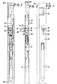
- Figur 1 eine Vorderansicht eines Teiles einer neuerungsgemäßen Runge,
- Figur 2 eine Aufsicht auf die neuerungsgemäße Runge nach Fig. 1 nach entfernter Rückplatte,
- Figur 3 einen Längsschnitt durch eine neuerungsgemäße Runge längs der Linie 111-111 der Fig. 2,
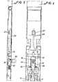
- Figur 4 eine Aufsicht auf eine modifizierte Runge nach entfernter Rückplatte,
- Figur 5 einen Längsschnitt durch eine modifizierte Runge längs der Linie V-V der Fig. 4.
- Die konstruktive Bauart der neuerungsgemäßen Runge 10 ist ansich beispielsweise durch die Druckschrift DE-C-1 780 395 bzw. die Druckschrift DE-A-24 44 021 bekannt. Danach besteht sie aus einer nicht näher dargestellten Befestigungsvorrichtung, mit welcher sie an der Seitenkante der Ladeplattform durch Betätigen eines Bedienungshebels 11 befestigbar ist. Mit dem gleichen Bedienungshebel 11 ist ein Arretierbolzen 12 in der Runge axial verschiebbar, dessen freies Ende in einen an der Seitenplanke 14 des Fahrzeugs angebrachten Arretierbügel 15 eingeführt werden kann. Das Ausführungsbeispiel gemäß der Fig. 1-3 zeigt eine Runge mit einem Arretierbolzen 12 für den Anschluß einer Seitenplanke 14. Sollen zwei Seitenplanken an eine gemeinsame Runge angeschlossen werden, weißt die Runge 2 solche Arretierbolzen auf, wie dies in dem Ausführungsbeispiel gemäß Fig. 4 und 5 dargestellt ist.
- Im Inneren der Runge 10 ist eine Halterung 13 für ein ösenförmiges Organ 16 angebracht, das als zweiarmiger Hebel ausgebildet und mit einem Drehzapfen 17 versehen ist, der durch die Halterung 13 an der Frontplatte 18 der Runge befestigt ist. Das als zweiarmiger Hebel ausgebildete ösenförmige Organ 16 besteht aus einem ersten Arm 19, in welchem der Drehzapfen 17 befestigt ist, sowie einem zweiten Arm 20, welcher als Öse ausgebildet ist. Die Öse ist um eine Drehachse 21 in einem Lager 22 drehbar gelagert, wobei die Drehachse 21 rechtwinklig zur Achse des Drehzapfens 17 ausgerichtet ist. Die Achse des Drehzapfens 17 ist gleichzeitig die Schwenkachse des zweiarmigen Hebels, dessen erster Arm 19 exzentrisch durch eine Feder 23 so belastet ist, daß das ösenförmige Organ 16 wie ein bistabiles Sperrgetriebe in jeder der beiden Endstellungen stabil gehalten ist. Die Fig. 1 und 2 veranschaulichen das ösenförmige Organ 16 in einer aus der Runge teilweise ausgeschwenkten Stellung, in welcher sich die Öse 20 außerhalb der Runge befindet, während der erste Arm 19 in dem Bewegungsbereich des Arretierbolzens 12 innerhalb der Runge geschwenkt ist. In dieser Stellung wird der Arretierbolzen 12 daran gehindert, sich bei Betätigung des Bedienungshebels 11 mehr als ein kurzes Stück entsprechend dem Schwenkradius des ösenförmigen Organs 16 zu bewegen. Ein vom Arretierbolzen 12 abstehender Absatz 24 stößt bei Betätigung des Bedienungshebels 11 gegen den zweiten Arm 19, wodurch der Arretierbolzen 12 nicht aus dem Arretierbügel 15 in der Seitenplanke 14 herausgezogen und so die Seitenplanke nicht freigegeben werden kann.
- Eine Ladeplattform eines LKW's hat gewöhnlich zwischen 6-12 Rungen und ebensoviele neuerungsgemäße Ösen, durch die ein Drahtseil gezogen und endseitig plombiert wird, wodurch weder die Seitenplanken der Ladeplattform herabgeklappt noch die Rungen von dieser entfernt werden können. Nach Entfernung des Plombierungsdrahtseils kann das ösenförmige Organ 16 um den Drehzapfen 17 geschwenkt werden, und zwar etwa um 90°, wodurch die Öse 20 durch eine Ausnehmung 25 in der Frontplatte der Runge in diese eingeschwenkt wird, dabei wird der 1. Arm 19 aus dem Bewegungsbereich des Arretierbolzens 12 geschwenkt und der Absatz 24 kann sich frei an dem ösenförmigen Organ 16 vorbeibewegen.
- Durch die exzentrische und seitlich versetzte Anordnung des Angriffpunktes der Feder 23 in Bezug auf den Drehzapfen 17 ergibt sich ein bistabiles Sperrgetriebe. Beim Schwenken des ösenförmigen Organs wird die Feder 23, deren erstes Ende sich gegen die Rungenwand abstützt und deren zweites Ende mit dem ösenförmigen Organ 16 im Eingriff ist, um das erste Ende geschwenkt, bis zum Erreichen des Todpunktes gespannt und bei weiterem Schwenken wieder entspannt, wodurch das ösenförmige Organ in seinen beiden Endstellungen durch Federdruck stabil gehalten wird, während in Zwischenstellungen die Feder bestrebt ist, das Organ in eine dieser Endstellungen, entsprechend der Lage der Zwischenstellung zum Todpunkt zu bringen.
- Sind die Rungen der Ladeplattform mit abnehmbaren vertikalen Stützen für eine Abdeckplane oder dergleichen versehen, so wie dies beispielsweise in der deutschen Patentschrift 1 956 809 beschrieben ist, ist es mit Rücksicht auf die Forderungen der TIR-Konvention wichtig, daß die Abdeckplane nicht abgenommen werden kann, ohne die Plombierung zu beschädigen. Um dies sicherzustellen ist neuerungsgemäß der Arretierbolzen 12, wie in Fig. 4 und 5 dargestellt, mit einem Riegel 26 versehen, der in einen Sperrbügel 27 in der abnehmbaren vertikalen Stütze 28 einführbar ist.
- In Sperrstellung des Arretierbolzens 12 wird bei dieser Ausführung somit sowohl die Seitenplanke wie auch die Stütze für die Abdeckplane verriegelt.
Claims (3)
Priority Applications (3)
| Application Number | Priority Date | Filing Date | Title |
|---|---|---|---|
| AT81850202T ATE25048T1 (de) | 1980-11-03 | 1981-10-30 | Runge fuer ladeplattformen. |
| EP86101666A EP0208047B1 (de) | 1980-11-03 | 1981-10-30 | Vorrichtung an Rungen für Ladeplattformen |
| DE8686101666T DE3176850D1 (en) | 1980-11-03 | 1981-10-30 | Connecting devices for load platform stanchions |
Applications Claiming Priority (2)
| Application Number | Priority Date | Filing Date | Title |
|---|---|---|---|
| DE8029162U | 1980-11-03 | ||
| DE8029162U DE8029162U1 (de) | 1980-11-03 | 1980-11-03 | Runge für Ladeplattformen |
Related Child Applications (1)
| Application Number | Title | Priority Date | Filing Date |
|---|---|---|---|
| EP86101666.5 Division-Into | 1986-02-10 |
Publications (3)
| Publication Number | Publication Date |
|---|---|
| EP0051575A2 EP0051575A2 (de) | 1982-05-12 |
| EP0051575A3 EP0051575A3 (en) | 1984-12-27 |
| EP0051575B1 true EP0051575B1 (de) | 1987-01-21 |
Family
ID=6720237
Family Applications (1)
| Application Number | Title | Priority Date | Filing Date |
|---|---|---|---|
| EP81850202A Expired EP0051575B1 (de) | 1980-11-03 | 1981-10-30 | Runge für Ladeplattformen |
Country Status (4)
| Country | Link |
|---|---|
| EP (1) | EP0051575B1 (de) |
| AT (1) | ATE36682T1 (de) |
| DE (3) | DE8029162U1 (de) |
| ES (1) | ES270863Y (de) |
Families Citing this family (7)
| Publication number | Priority date | Publication date | Assignee | Title |
|---|---|---|---|---|
| FR2535655A1 (fr) * | 1982-11-08 | 1984-05-11 | Trailor Sa | Rancher articule verrouillable pour vehicule de transport |
| SE8304867D0 (sv) * | 1983-09-12 | 1983-09-12 | Kinnegrip Ab | Lostagbar vertikal stolpe till lastflak med av denna uppburen stotta till kapell och liknande |
| SE454974B (sv) * | 1986-11-04 | 1988-06-13 | Armaton Ab | Anordning vid rorformig flakstolpe |
| SE454973B (sv) * | 1986-11-04 | 1988-06-13 | Armaton Ab | Anordning vid flakstolpe med kapellstotta |
| SE460039B (sv) * | 1987-11-02 | 1989-09-04 | Armaton Ab | Anordning vid lastvagnsflaklaem |
| IT214599Z2 (it) * | 1988-05-16 | 1990-05-09 | Viberti Off Spa | Dispositivo per la piombatura degli elementi di recinzione di un cassone di veicolo industriale |
| EP0544694B1 (de) * | 1990-07-09 | 1995-12-27 | Göran ROSEN | Verfahren zur herstellung von rungen für ladeplattformen und gemäss dem verfahren hergestellte rungen |
Family Cites Families (1)
| Publication number | Priority date | Publication date | Assignee | Title |
|---|---|---|---|---|
| SE450241B (sv) * | 1979-03-13 | 1987-06-15 | Sture Simme | Anordning vid ett lastbilsflak eller liknande for att losbart hopkoppla en lem med en stolpe eller en stolpe med flaket |
-
1980
- 1980-11-03 DE DE8029162U patent/DE8029162U1/de not_active Expired
-
1981
- 1981-10-30 AT AT86101666T patent/ATE36682T1/de active
- 1981-10-30 DE DE8181850202T patent/DE3175847D1/de not_active Expired
- 1981-10-30 DE DE8686101666T patent/DE3176850D1/de not_active Expired
- 1981-10-30 EP EP81850202A patent/EP0051575B1/de not_active Expired
- 1981-11-03 ES ES1981270863U patent/ES270863Y/es not_active Expired
Also Published As
| Publication number | Publication date |
|---|---|
| DE8029162U1 (de) | 1981-03-19 |
| DE3176850D1 (en) | 1988-09-29 |
| EP0051575A2 (de) | 1982-05-12 |
| EP0051575A3 (en) | 1984-12-27 |
| ES270863Y (es) | 1984-03-16 |
| ES270863U (es) | 1983-09-01 |
| ATE36682T1 (de) | 1988-09-15 |
| DE3175847D1 (en) | 1987-02-26 |
Similar Documents
| Publication | Publication Date | Title |
|---|---|---|
| DE69518155T2 (de) | Greifvorrichtung für behälter | |
| EP0085851A1 (de) | Kraftfahrzeug mit einer Heckklappe | |
| DE68909281T2 (de) | Verstellbare Säule für ein Lastkraftfahrzeug mit verschiebbarer Abdeckung. | |
| DE19738130A1 (de) | Vorrichtung zum Sichern von Fracht oder Gepäck in einem Fracht- oder Gepäckraum | |
| DE2731386A1 (de) | Rechteckiger behaelter von der groesse eines wagenaufbaus, insbesondere container nach iso-norm | |
| EP1184224B1 (de) | Transportbehälter-Einrichtung für Fahrzeuge, wie z.B. Durchladeeinrichtung | |
| DE3739921C2 (de) | ||
| EP0051575B1 (de) | Runge für Ladeplattformen | |
| DE69109486T2 (de) | Vorrichtung an runger für ladeplattformen an fahrzeugen mit abdeckung und abdeckungshalter. | |
| EP0831001B1 (de) | Hängerunge | |
| DE2839786C3 (de) | Hebedach-Anordnung für ein Fahrzeug | |
| DE69300834T2 (de) | Runge für eine Fahrzeug-Ladeplattform. | |
| DE2601128A1 (de) | Fahrzeugaufbau fuer lastfahrzeuge | |
| DE3841247C2 (de) | Vorrichtung zum Verriegeln einer umlegbaren Rückenlehne eines Kraftfahrzeugsitzes | |
| DE69404212T2 (de) | Klappe zum Schliessen einer Öffnung im unteren Teil eines Wagenkastens | |
| DE3048652C2 (de) | Handbetätigungsanordnung für Frachtladesysteme | |
| EP0075038B1 (de) | Drehriegelspannverschluss für ein bewegliches Aufbauteil von Lastfahrzeugen, Containern und dergleichen | |
| EP1777103B1 (de) | Universal-Verriegelung für Container oder Aufbauten verschiedener Größen auf einem Fahrzeug | |
| EP0208047B1 (de) | Vorrichtung an Rungen für Ladeplattformen | |
| DE1956392C3 (de) | Zusammenschiebbares Verdeck, insbesondere für Lastkraftwagen und -anhänger | |
| DE2035179A1 (de) | Tür Festlegungsvorrichtung | |
| DE2159891C3 (de) | Drehgelenk für eine Bordwand eines Fahrzeugaufbaus | |
| DE1137652B (de) | Betaetigungsvorrichtung eines Fahrzeugtuerverschlusses | |
| DE3215476A1 (de) | Dachgepaecktraeger fuer kraftfahrzeuge | |
| DE3701859C2 (de) |
Legal Events
| Date | Code | Title | Description |
|---|---|---|---|
| PUAI | Public reference made under article 153(3) epc to a published international application that has entered the european phase |
Free format text: ORIGINAL CODE: 0009012 |
|
| AK | Designated contracting states |
Designated state(s): AT BE CH DE FR GB IT NL SE |
|
| PUAL | Search report despatched |
Free format text: ORIGINAL CODE: 0009013 |
|
| AK | Designated contracting states |
Designated state(s): AT BE CH DE FR GB IT LI NL SE |
|
| 17P | Request for examination filed |
Effective date: 19850114 |
|
| GRAA | (expected) grant |
Free format text: ORIGINAL CODE: 0009210 |
|
| AK | Designated contracting states |
Kind code of ref document: B1 Designated state(s): AT BE CH DE FR GB IT LI NL SE |
|
| REF | Corresponds to: |
Ref document number: 25048 Country of ref document: AT Date of ref document: 19870215 Kind code of ref document: T |
|
| REF | Corresponds to: |
Ref document number: 3175847 Country of ref document: DE Date of ref document: 19870226 |
|
| ITF | It: translation for a ep patent filed | ||
| ET | Fr: translation filed | ||
| PLBE | No opposition filed within time limit |
Free format text: ORIGINAL CODE: 0009261 |
|
| STAA | Information on the status of an ep patent application or granted ep patent |
Free format text: STATUS: NO OPPOSITION FILED WITHIN TIME LIMIT |
|
| 26N | No opposition filed | ||
| PGFP | Annual fee paid to national office [announced via postgrant information from national office to epo] |
Ref country code: GB Payment date: 19891031 Year of fee payment: 9 |
|
| PGFP | Annual fee paid to national office [announced via postgrant information from national office to epo] |
Ref country code: CH Payment date: 19891101 Year of fee payment: 9 |
|
| PGFP | Annual fee paid to national office [announced via postgrant information from national office to epo] |
Ref country code: BE Payment date: 19891108 Year of fee payment: 9 |
|
| PG25 | Lapsed in a contracting state [announced via postgrant information from national office to epo] |
Ref country code: GB Effective date: 19901030 |
|
| PG25 | Lapsed in a contracting state [announced via postgrant information from national office to epo] |
Ref country code: LI Effective date: 19901031 Ref country code: CH Effective date: 19901031 Ref country code: BE Effective date: 19901031 |
|
| PGFP | Annual fee paid to national office [announced via postgrant information from national office to epo] |
Ref country code: NL Payment date: 19901031 Year of fee payment: 10 Ref country code: AT Payment date: 19901031 Year of fee payment: 10 |
|
| BERE | Be: lapsed |
Owner name: ROSEN GORAN Effective date: 19901031 |
|
| GBPC | Gb: european patent ceased through non-payment of renewal fee | ||
| REG | Reference to a national code |
Ref country code: CH Ref legal event code: PL |
|
| PG25 | Lapsed in a contracting state [announced via postgrant information from national office to epo] |
Ref country code: AT Effective date: 19911030 |
|
| PGFP | Annual fee paid to national office [announced via postgrant information from national office to epo] |
Ref country code: FR Payment date: 19911030 Year of fee payment: 11 |
|
| ITTA | It: last paid annual fee | ||
| PGFP | Annual fee paid to national office [announced via postgrant information from national office to epo] |
Ref country code: DE Payment date: 19911228 Year of fee payment: 11 |
|
| PG25 | Lapsed in a contracting state [announced via postgrant information from national office to epo] |
Ref country code: NL Effective date: 19920501 |
|
| NLV4 | Nl: lapsed or anulled due to non-payment of the annual fee | ||
| PGFP | Annual fee paid to national office [announced via postgrant information from national office to epo] |
Ref country code: SE Payment date: 19921030 Year of fee payment: 12 |
|
| PG25 | Lapsed in a contracting state [announced via postgrant information from national office to epo] |
Ref country code: FR Effective date: 19930630 |
|
| PG25 | Lapsed in a contracting state [announced via postgrant information from national office to epo] |
Ref country code: DE Effective date: 19930701 |
|
| REG | Reference to a national code |
Ref country code: FR Ref legal event code: ST |
|
| PG25 | Lapsed in a contracting state [announced via postgrant information from national office to epo] |
Ref country code: SE Effective date: 19931031 |
|
| EUG | Se: european patent has lapsed |
Ref document number: 81850202.3 Effective date: 19940510 |