EP0046305A2 - Procédé et dispositif de commande pour moteur à combustion interne - Google Patents
Procédé et dispositif de commande pour moteur à combustion interne Download PDFInfo
- Publication number
- EP0046305A2 EP0046305A2 EP81106425A EP81106425A EP0046305A2 EP 0046305 A2 EP0046305 A2 EP 0046305A2 EP 81106425 A EP81106425 A EP 81106425A EP 81106425 A EP81106425 A EP 81106425A EP 0046305 A2 EP0046305 A2 EP 0046305A2
- Authority
- EP
- European Patent Office
- Prior art keywords
- engine
- signal
- rotational speed
- air intake
- correction
- Prior art date
- Legal status (The legal status is an assumption and is not a legal conclusion. Google has not performed a legal analysis and makes no representation as to the accuracy of the status listed.)
- Granted
Links
Images


Classifications
-
- F—MECHANICAL ENGINEERING; LIGHTING; HEATING; WEAPONS; BLASTING
- F02—COMBUSTION ENGINES; HOT-GAS OR COMBUSTION-PRODUCT ENGINE PLANTS
- F02D—CONTROLLING COMBUSTION ENGINES
- F02D41/00—Electrical control of supply of combustible mixture or its constituents
- F02D41/24—Electrical control of supply of combustible mixture or its constituents characterised by the use of digital means
- F02D41/26—Electrical control of supply of combustible mixture or its constituents characterised by the use of digital means using computer, e.g. microprocessor
-
- F—MECHANICAL ENGINEERING; LIGHTING; HEATING; WEAPONS; BLASTING
- F02—COMBUSTION ENGINES; HOT-GAS OR COMBUSTION-PRODUCT ENGINE PLANTS
- F02P—IGNITION, OTHER THAN COMPRESSION IGNITION, FOR INTERNAL-COMBUSTION ENGINES; TESTING OF IGNITION TIMING IN COMPRESSION-IGNITION ENGINES
- F02P5/00—Advancing or retarding ignition; Control therefor
- F02P5/04—Advancing or retarding ignition; Control therefor automatically, as a function of the working conditions of the engine or vehicle or of the atmospheric conditions
- F02P5/145—Advancing or retarding ignition; Control therefor automatically, as a function of the working conditions of the engine or vehicle or of the atmospheric conditions using electrical means
- F02P5/15—Digital data processing
- F02P5/1502—Digital data processing using one central computing unit
-
- Y—GENERAL TAGGING OF NEW TECHNOLOGICAL DEVELOPMENTS; GENERAL TAGGING OF CROSS-SECTIONAL TECHNOLOGIES SPANNING OVER SEVERAL SECTIONS OF THE IPC; TECHNICAL SUBJECTS COVERED BY FORMER USPC CROSS-REFERENCE ART COLLECTIONS [XRACs] AND DIGESTS
- Y02—TECHNOLOGIES OR APPLICATIONS FOR MITIGATION OR ADAPTATION AGAINST CLIMATE CHANGE
- Y02T—CLIMATE CHANGE MITIGATION TECHNOLOGIES RELATED TO TRANSPORTATION
- Y02T10/00—Road transport of goods or passengers
- Y02T10/10—Internal combustion engine [ICE] based vehicles
- Y02T10/40—Engine management systems
Definitions
- the present invention relates to a method and an apparatus for controlling an internal combustion engine.
- the method and the apparatus for controlling an internal combustion engine according to the present invention can be used, for example, for controlling an internal combustion engine with an electronic fuel injecting device in which the rotational speed of the engine in the idle running condition and in the low speed running condition is controlled in accordance with the amount of the fuel injection and the ignition timing.
- the base amount of the fuel injection is determined so as to realize an approximate stoichiometrical air fuel mixing ratio, which base amount is obtained by effecting the rotational speed correction to the amount of the fuel injection determined by the two dimensional map of the rotational speed and the air intake pressure or determined in'accordance with the air intake pressure.
- the thus determined base amount of the fuel injection is corrected by the coolant temperature, the intake air temperature, the battery voltage, and the like, and the corrected base amount of the fuel injection is used for control.
- the base amount of the fuel injection is determined mostly by the air intake pressure. The influence of the engine rotational speed on the base amount of the fuel injection is less than that of the air intake pressure.
- the correction of the base amount of the fuel injection is carried out in such a manner that: when the rotational speed of the engine increases over a predetermined rotational speed and the air intake pressure decreases below a predetermined pressure, the air-fuel ratio of the engine is made rich, while when the rotational speed of the engine decreases below a predetermined rotational speed and the air intake pressure increases over a predetermined pressure, the air-fuel ratio of the engine is made lean.
- the present invention is proposed in order to solve the above described problems in the prior art internal combustion engine with an electronic fuel injecting device.
- a method for controlling an internal combustion engine having a sensor for sensing the air intake pressure of the engine and producing the signal of the sensed air intake pressure, a sensor for sensing the rotational speed of the engine and producing the signal of the sensed rotational speed and a computer for carrying out the calculation using said produced signals of the sensed air intake pressure and the sensed rotational speed and producing at least a control value, said produced control value being used for controlling the operation of said engine; wherein the calculation carried out in said computer comprises the steps of: taking the signals produced by said sensor for sensing the air intake pressure and said sensor for sensing the rotational speed successively at the selected interval, calculating the value APm which is the difference between the signal of the air intake pressure sensor in the preceding time unit and the signal of the air intake pressure sensor in the present time unit and the value AN which is the difference between the signal of the rotational speed sensor in the preceding time unit and the signal of the rotational speed sensor in the present time unit, calculating the correction value from said calculated value APm
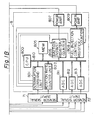
- FIG. 1 An apparatus for controlling an internal combustion engine in accordance with an embodiment of the present invention is illustrated in Fig. 1.
- the internal combustion engine 11 is of the six cylinder type.
- the air brought in through an air cleaner is sent to the engine 11 via the throttle valve 9 and the intake manifold 13.
- a semiconductor pressure sensor 12 for sensing the pressure of the intake manifold 13 is provided.
- a fuel injection valve 4 for injecting the fuel under regulated pressure is provided adjacent to the intake port of the cylinder of the engine 11.
- the ignition system comprising the ignition coil 5 and the distributor 6 is provided.
- the rotational angle sensor 17 for sensing the rotational angle of the engine is provided in the distributor 6 which rotates once every two rotations of the crank shaft of the engine.
- the pressure sensor 12 for sensing the pressure of the intake manifold 13, the throttle sensor 14 for sensing the perfect closure or the approximately perfect closure of the throttle valve 9, the air intake temperature sensor 15 for sensing the temperature of the air intake, and the coolant temperature sensor 18 for sensing the temperature of the coolant water which represents the warming-up condition of the engine are provided.
- the computer unit 8 is provided for carrying out the control of the engine in accordance with the signals produced in the above described sensors.
- the signals from the sensors are supplied to the computer unit 8 via the sensor signal inputting circuits 71 and 72.
- the computer unit 8 comprises the central processor unit (CPU) 800, the common bus 810, the interruption commanding unit 801, the counter unit 802 for counting the rotations, the analog-to-digital (A-D) converters 811, 812 and 813, the memory unit 805, the register/counter unit 806 for controlling the ignition instant, the register/counter unit 808 for controlling the time for the fuel injection, and the power amplifiers 807 and 809.
- the rotational angle sensor 17 produces the signals (A), (B) and (C) which are supplied to the interruption commanding unit 801 and the counter unit 802 for counting the rotations through the sensor signal inputting circuit 71.
- the interruption commanding unit 801 produces the interruption commanding signals (D) and (E).
- the pulse (D) is phase- shifted by 60°CA to produce the pulse (F).
- the signal (G) which.indicates the top dead center of the sixth cylinder is obtained from the signals (B) and (C).
- the signal (H) which indicates the top dead center of the first cylinder is obtained from the signals (A) and (C).
- the counting period of the counter 806 is represented by the wave form (I).
- the counting-down is started with the pulse (F) and is completed at the falling edge of the wave form (I).
- the falling edge of the wave form (I) represents the ignition timing.
- the fuel is injected into the first, the fifth and the third cylinder in accordance with the fuel injection pulse (J), and is injected into the second, fourth and the sixth cylinder in accordance with the fuel injection pulse (K).
- the signals from the coolant temperature sensor 18, the throttle sensor 14, the pressure sensor 12 and the air intake temperature sensor 15 are supplied to the A-D converters 811, 812 and 813 through the sensor signal inputting circuit 72.
- the interruption commanding unit 801 commands the interruption process of the calculation of the amount of the fuel injection and the calculation of the ignition timing through the common bus 810 to the CPU 800 in accordance with the signal of the rotational angle from the rotational angle sensor 17.
- the timing signal for controlling the starting instant of the operation is supplied to the register/counter unit 806 for controlling the ignition timing and to the register/counter 808 for controlling the fuel injection time.
- the counter unit 802 for counting the rotations receives the signal from the rotational angle sensor 17 and counts the period of a predetermined rotational angle; using the clock signal, with a predetermined frequency so that the rate of rotations of the engine is calculated.
- the signals from the coolant temperature sensor 18, the throttle sensor 14, the pressure sensor 12 and the air intake temperature sensor 15 are analog-to--digitally converted in the A-D converters 811, 812 and 813 and the converted signals are read-in by the CPU 800 via the common bus 810.
- the control program of the CPU and the data from the units 801, 802, 811, 812 and 813 are stored.
- the register/counter unit 806 for controlling the ignition timing produces the signal indicating the timing and the time corresponding to the rotational angle of the engine from the digital signal representing the duration of the current through the ignition coil and the timing of the current shut down which are calculated in the CPU 800.
- the output signal of the unit 806 is amplified by the power amplifier 807.
- the output signal of the power amplifier 807 is supplied to the ignition coil 5 and controls the timing of the current shut down of the ignition coil 5.
- the register/counter unit 808 for controlling the fuel injection duration converts the digital signal representing the valve opening duration of the fuel injection valve 4, which is calculated by the CPU 800, that is the amount of the fuel injection, into the pulse signal having the pulse width indicating the valve opening duration of the fuel injection valve 4.
- the output signal of the unit 808 is amplified by the power amplifier 809, the output signal of which is supplied to the fuel injection valve 4.
- the interruption commanding unit 801 receives the rotational angle signal from the rotational angle sensor 17 and produces the signal for commanding the interruptions for the calculation of the ignition timing and the calculation of the amount of the fuel injection.
- the interruption commanding signal (D) is of a half frequency of the rotational angle signal (C) of the third rotational angle sensor and is produced immediately after the rotational angle signal (A) of the first rotational angle sensor.
- the signal (D) is produced six times in every two rotations of the rotating shaft of the engine.
- the signal (D) is produced once every l20°CA.
- the signal (D) commands the CPU 800 to carry out the interruption for the calculation of the ignition timing.
- the interruption commanding unit 801 divides the frequency of the signal of the third rotational angle sensor by six so that the interruption commanding signal (E) is produced at every 360°CA from the 300°CA of the engine.
- the interruption commanding signal (E) is the signal for commanding the computer circuit 8 to carry out the interruption for the calculation of the amount of the fuel injection.
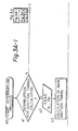
- Step al proceeds to Step a2 where the signal N representing the rotational speed of the engine obtained by the counter unit 802 for counting the rotational speed and the air intake pressure Pm obtained by the A-D coverter units 811 through 813 are read-out from the RAM of the memory unit 805.
- Step a3 the base ignition timing is obtained from the memory unit 805 where the relationship between the ignition timing, the rotational speed and the air intake pressure is stored in the form of a two dimensional map.
- Steps a4, a5, a6 and a7 The determination whether or not the conditions are established for executing the correction of the control value, such as the ignition timing and the amount of the fuel injection, is carried out in Steps a4, a5, a6 and a7. If the conditions are not established, the process proceeds to Step b7. If the conditions are established, the correction flag which represents the allowableness of the correction of the control value of the engine is selected in Step a8 so as to indicate that the correction is allowable.
- Step a9 the signal Pm' of the air intake pressure in the preceding operation time unit is read-out by the CPU 800 from the memory unit 805.
- Step a10 the signal Pm' which has been read-in in Step a2 is written-in to the RAM of the memory unit. The thus written-in signal Pm' is used as the signal Pm' in the next operation time unit for the interruption process for controlling the ignition timing.
- the correction value for the ignition timing corresponding to ⁇ Pm is read-out from the map indicating the correction value for the ignition timing stored in the ROM region of the memory unit 805.
- the processing of the signal representing the rotational speed N is carried out in Steps b2, b3, b4 and b5 in the similar manner as in Steps a9, a10, all and a12 for the signal Pm. Accordingly, the correction value for the ignition timing corresponding to the deviation AN of the rotational speed is read-out from the map for the correction of the ignition instant stored in the ROM region of the memory unit 805.
- Step b6 the correction value for the ignition instant corresponding to ⁇ Pm and AN are added to the base value of the ignition timing.
- Step b7 the correction in accordance with the coolant temperature and the air intake temperature is carried out to the ignition timing to which the correction in accordance with APm and AN has been carried out.
- the thus corrected data is registered in the register of the counter unit 806 in Step b8.
- Step b9 the interruption process is completed in Step b9.
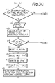
- Step c3 the calculation of the base value of the fuel injection is carried out using the obtained signal N and Pm. If it is determined in Step c4 that the correction flag Fa is established due to the latest interruption calculation for the ignition timing, the process proceeds to Step c5 where the correction flag Fa is reset.
- Steps c6, c7, c8, c9, dl, d2, d3 and d4 the processes similar to that of Steps a9, a10, all, bl, b2, b3, b4 and b5 are carried out so that the correction value for the base amount of the fuel injection corresponding to the deviation APm' of the air intake pressure and the deviation ⁇ N' of the rotational speed is obtained.
- Step d5 the correction value for the base amount of the fuel injection is multiplied by the correction ratio for APm' and AN'.
- Step d6 the correction is carried out to the amount of the fuel injection by using the values of the coolant temperature, the air intake temperature, the battery voltage and the like.
- the thus corrected data is registered in the register of the counter unit 808 in Step d7.
- the interruption process is completed in Step b9.
- the predetermined change of the value of correction for the amount of the fuel injection and the ignition timing in accordance with the deviations of the rotational speed of the engine stored in the R OM the memory unit 805 is illustrated in Figs. 4 and 5.
- the rotational speed tends to decrease i.e. the variation of the rotational speed is negative
- the correction is carried out in the direction to increase the amount of the fuel injection, and hence the torque of the engine is caused to be increased, and accordingly the reduction of the rotational speed is prevented.
- the rotational speed tends to increase i.e the variation of the rotational speed is positive
- the correction is carried out in the direction to decrease the amount of the fuel injection, and hence the torque of the engine is caused to ...
- the correction value in the negative side is selected, in practice, larger than the correction value in the positive side.
- the rotational speed tends to decrease i.e. the variation of the rotational speed is negative
- the correction is carried out in the direction of the advanced angle regarding the ignition timing and hence the torque of the engine is caused to be increased, and accordingly the decrease of the rotational speed is prevented. Contrary to this, when the rotational speed tends to increase, i.e.
- the abscissa represents the variation of the rotational speed of the engine in rpm and the ordinate represents the correction ratio for the amount of the base fuel injection.
- the abscissa represents the variation of the rotational speed of the engine in rpm and the ordinate represents the correction value for the ignition timing in °CA.
- the corrections of the amount of the fuel injection and the ignition timing by the variation of the air intake pressure are carried out in a similar manner as the corrections by the variation of the rotational speed of the engine, as described above.
- the present invention is applicable to multicylinder type internal combustion engines, such as those of four or eight cylinder types and mass flow type internal combustion engines, although the speed density type internal combustion engine of a six cylinder type is used in the above described embodiment.
Landscapes
- Engineering & Computer Science (AREA)
- Chemical & Material Sciences (AREA)
- Combustion & Propulsion (AREA)
- Mechanical Engineering (AREA)
- General Engineering & Computer Science (AREA)
- Computer Hardware Design (AREA)
- Microelectronics & Electronic Packaging (AREA)
- Theoretical Computer Science (AREA)
- Signal Processing (AREA)
- Electrical Control Of Air Or Fuel Supplied To Internal-Combustion Engine (AREA)
- Combined Controls Of Internal Combustion Engines (AREA)
- Electrical Control Of Ignition Timing (AREA)
Applications Claiming Priority (2)
| Application Number | Priority Date | Filing Date | Title |
|---|---|---|---|
| JP112947/80 | 1980-08-19 | ||
| JP11294780A JPS5738642A (en) | 1980-08-19 | 1980-08-19 | Method of internal-combustion engine control |
Publications (3)
| Publication Number | Publication Date |
|---|---|
| EP0046305A2 true EP0046305A2 (fr) | 1982-02-24 |
| EP0046305A3 EP0046305A3 (en) | 1982-07-28 |
| EP0046305B1 EP0046305B1 (fr) | 1986-12-17 |
Family
ID=14599494
Family Applications (1)
| Application Number | Title | Priority Date | Filing Date |
|---|---|---|---|
| EP81106425A Expired EP0046305B1 (fr) | 1980-08-19 | 1981-08-19 | Procédé et dispositif de commande pour moteur à combustion interne |
Country Status (4)
| Country | Link |
|---|---|
| US (1) | US4479186A (fr) |
| EP (1) | EP0046305B1 (fr) |
| JP (1) | JPS5738642A (fr) |
| DE (1) | DE3175722D1 (fr) |
Cited By (10)
| Publication number | Priority date | Publication date | Assignee | Title |
|---|---|---|---|---|
| EP0066727A2 (fr) * | 1981-06-04 | 1982-12-15 | Toyota Jidosha Kabushiki Kaisha | Procédé et appareil pour commander un moteur à combustion interne comprenant un système d'injection de combustible |
| FR2524554A1 (fr) * | 1982-04-02 | 1983-10-07 | Honda Motor Co Ltd | Appareil de reglage du fonctionnement d'un moteur a combustion interne |
| FR2538855A1 (fr) * | 1982-12-30 | 1984-07-06 | Renault | Procede de stabilisation de la vitesse de rotation a vide d'un moteur a allumage commande |
| FR2539820A1 (fr) * | 1983-01-20 | 1984-07-27 | Texas Instruments France | Procede de commande d'allumage pour moteur a combustion interne et circuit electronique pour sa mise en oeuvre |
| EP0162470A2 (fr) * | 1984-05-23 | 1985-11-27 | Honda Giken Kogyo Kabushiki Kaisha | Méthode de commande de l'alimentation en carburant d'un moteur à combustion interne |
| EP0204524A2 (fr) * | 1985-05-31 | 1986-12-10 | Honda Giken Kogyo Kabushiki Kaisha | Méthode de commande de l'alimentation en carburant pour moteur à combustion interne au ralenti |
| US4723519A (en) * | 1985-06-17 | 1988-02-09 | Toyota Jidosha Kabushiki Kaisha | Ignition timing control system for an internal combustion engine |
| DE4010808A1 (de) * | 1990-04-04 | 1991-10-10 | Bosch Gmbh Robert | Verfahren zur leerlaufdrehzahlstabilisierung einer brennkraftmaschine |
| FR2678986A1 (fr) * | 1991-07-09 | 1993-01-15 | Siemens Automotive Sa | Procede de correction en regime transitoire de l'avance a l'allumage d'un moteur a combustion interne et son application au lissage des a-coups du regime du moteur. |
| WO1994015086A1 (fr) * | 1992-12-18 | 1994-07-07 | Bugatti Electronics S.R.L. | Systeme multifonctions de commande a retour pour moteurs a combustion interne |
Families Citing this family (26)
| Publication number | Priority date | Publication date | Assignee | Title |
|---|---|---|---|---|
| JPS58170831A (ja) * | 1982-03-31 | 1983-10-07 | Toyota Motor Corp | 電子制御燃料噴射装置 |
| JPS5993945A (ja) * | 1982-11-19 | 1984-05-30 | Nippon Denso Co Ltd | 内燃機関のアイドル運転制御方法 |
| DE3243235A1 (de) * | 1982-11-23 | 1984-05-24 | Robert Bosch Gmbh, 7000 Stuttgart | Einrichtung zum daempfen von ruckelschwingungen bei einer brennkraftmaschine in einem kraftfahrzeug |
| US4556942A (en) * | 1983-05-27 | 1985-12-03 | Allied Corporation | Microprocessor based engine control system for controlling heavy engine loads |
| JPS603448A (ja) * | 1983-06-20 | 1985-01-09 | Honda Motor Co Ltd | 内燃エンジンの作動状態制御方法 |
| JPH066979B2 (ja) * | 1983-08-22 | 1994-01-26 | トヨタ自動車株式会社 | 車両用無段変速機の制御装置 |
| JPS60135633A (ja) * | 1983-12-21 | 1985-07-19 | Mikuni Kogyo Co Ltd | 電子制御燃料供給装置 |
| DE3408002A1 (de) * | 1984-03-03 | 1985-09-12 | Vdo Adolf Schindling Ag, 6000 Frankfurt | Einrichtung zur herabsetzung von fahrzeuglaengsdynamik-instabilitaeten |
| JPS60237142A (ja) * | 1984-05-07 | 1985-11-26 | Toyota Motor Corp | 内燃機関の制御装置 |
| JPH0733804B2 (ja) * | 1984-05-12 | 1995-04-12 | マツダ株式会社 | エンジンの制御装置 |
| JP2511862B2 (ja) * | 1986-01-08 | 1996-07-03 | 株式会社日立製作所 | 内燃機関の点火時期制御方法 |
| JPH0523808Y2 (fr) * | 1986-02-17 | 1993-06-17 | ||
| JPS62240442A (ja) * | 1986-04-09 | 1987-10-21 | Hitachi Ltd | 燃料制御装置 |
| JP2791436B2 (ja) * | 1987-03-20 | 1998-08-27 | トヨタ自動車株式会社 | 車両用定速走行装置 |
| JPH01216053A (ja) * | 1988-02-24 | 1989-08-30 | Fuji Heavy Ind Ltd | エンジンの燃料噴射制御装置 |
| JP2832944B2 (ja) * | 1988-06-10 | 1998-12-09 | 株式会社日立製作所 | 計測データの遅れ補償方法 |
| JPH0765540B2 (ja) * | 1988-09-21 | 1995-07-19 | 松下電器産業株式会社 | エンジン制御装置 |
| JP3839119B2 (ja) * | 1997-02-13 | 2006-11-01 | 本田技研工業株式会社 | 4サイクルエンジンの行程判別装置 |
| JP3685369B2 (ja) * | 1999-01-26 | 2005-08-17 | 三菱電機株式会社 | 内燃機関の制御装置 |
| JP2002371899A (ja) * | 2001-06-15 | 2002-12-26 | Fujitsu Ten Ltd | エンジン制御装置 |
| JP2007009852A (ja) * | 2005-07-01 | 2007-01-18 | Hitachi Ltd | 内燃機関の燃料制御装置および燃料噴射時期制御方法 |
| JP4367398B2 (ja) * | 2005-10-19 | 2009-11-18 | トヨタ自動車株式会社 | 内燃機関の制御装置 |
| DE102008000916B4 (de) * | 2007-04-02 | 2021-12-16 | Denso Corporation | Verbrennungssteuerungsvorrichtung für direkt einspritzende Kompressionszündungskraftmaschine |
| FR2945078B1 (fr) * | 2009-04-29 | 2011-04-29 | Peugeot Citroen Automobiles Sa | Procede de controle du fonctionnement d'un moteur |
| US10859027B2 (en) | 2017-10-03 | 2020-12-08 | Polaris Industries Inc. | Method and system for controlling an engine |
| US11493014B2 (en) * | 2020-05-01 | 2022-11-08 | John C. Rhoades | Reluctor plate controller |
Citations (6)
| Publication number | Priority date | Publication date | Assignee | Title |
|---|---|---|---|---|
| GB2007392A (en) * | 1977-10-19 | 1979-05-16 | Hitachi Ltd | Input signal processor used in electronic engine control apparatus |
| US4184458A (en) * | 1977-10-19 | 1980-01-22 | Toyota Jidosha Kogyo Kabushiki Kaisha | Method of controlling fuel injection in engine and unit therefor |
| JPS5549541A (en) * | 1978-10-05 | 1980-04-10 | Nippon Denso Co Ltd | Electronic control fuel injection device |
| GB2031185A (en) * | 1978-09-06 | 1980-04-16 | Hitachi Ltd | Electronic control of an internal combustion engine |
| EP0017255A2 (fr) * | 1979-04-10 | 1980-10-15 | Hitachi, Ltd. | Appareil de traitement de signaux pour obtenir des paramètres de commande dans un système de commande électronique pour moteur à combustion interne |
| US4257377A (en) * | 1978-10-05 | 1981-03-24 | Nippondenso Co., Ltd. | Engine control system |
Family Cites Families (8)
| Publication number | Priority date | Publication date | Assignee | Title |
|---|---|---|---|---|
| FR2355437A6 (fr) * | 1972-05-10 | 1978-01-13 | Peugeot & Renault | Systeme de commande du type analogique-numerique-analogique a calculateur digital a fonctions multiples pour vehicule automobile |
| US4010717A (en) * | 1975-02-03 | 1977-03-08 | The Bendix Corporation | Fuel control system having an auxiliary circuit for correcting the signals generated by the pressure sensor during transient operating conditions |
| DE2507137A1 (de) * | 1975-02-19 | 1976-09-02 | Bosch Gmbh Robert | Verfahren und vorrichtung zur regelung des betriebsverhaltens einer brennkraftmaschine |
| JPS524926A (en) * | 1975-07-02 | 1977-01-14 | Nippon Denso Co Ltd | Electronic controlled fuel jet apparatus |
| IT1081383B (it) * | 1977-04-27 | 1985-05-21 | Magneti Marelli Spa | Apparecchiatura elettronica per il controllo dell'alimentazione di una miscela aria/benzina di un motore a combustione interna |
| JPS597017B2 (ja) * | 1977-05-18 | 1984-02-16 | トヨタ自動車株式会社 | 電子制御燃料噴射式内燃機関 |
| JPS6059418B2 (ja) * | 1977-05-31 | 1985-12-25 | 株式会社デンソー | 電子式燃料噴射制御装置 |
| JPS6060019B2 (ja) * | 1977-10-17 | 1985-12-27 | 株式会社日立製作所 | エンジンの制御方法 |
-
1980
- 1980-08-19 JP JP11294780A patent/JPS5738642A/ja active Granted
-
1981
- 1981-08-19 US US06/294,154 patent/US4479186A/en not_active Expired - Lifetime
- 1981-08-19 DE DE8181106425T patent/DE3175722D1/de not_active Expired
- 1981-08-19 EP EP81106425A patent/EP0046305B1/fr not_active Expired
Patent Citations (6)
| Publication number | Priority date | Publication date | Assignee | Title |
|---|---|---|---|---|
| GB2007392A (en) * | 1977-10-19 | 1979-05-16 | Hitachi Ltd | Input signal processor used in electronic engine control apparatus |
| US4184458A (en) * | 1977-10-19 | 1980-01-22 | Toyota Jidosha Kogyo Kabushiki Kaisha | Method of controlling fuel injection in engine and unit therefor |
| GB2031185A (en) * | 1978-09-06 | 1980-04-16 | Hitachi Ltd | Electronic control of an internal combustion engine |
| JPS5549541A (en) * | 1978-10-05 | 1980-04-10 | Nippon Denso Co Ltd | Electronic control fuel injection device |
| US4257377A (en) * | 1978-10-05 | 1981-03-24 | Nippondenso Co., Ltd. | Engine control system |
| EP0017255A2 (fr) * | 1979-04-10 | 1980-10-15 | Hitachi, Ltd. | Appareil de traitement de signaux pour obtenir des paramètres de commande dans un système de commande électronique pour moteur à combustion interne |
Cited By (15)
| Publication number | Priority date | Publication date | Assignee | Title |
|---|---|---|---|---|
| EP0066727A2 (fr) * | 1981-06-04 | 1982-12-15 | Toyota Jidosha Kabushiki Kaisha | Procédé et appareil pour commander un moteur à combustion interne comprenant un système d'injection de combustible |
| EP0066727A3 (en) * | 1981-06-04 | 1984-08-29 | Toyota Jidosha Kabushiki Kaisha | Device and method for controlling fuel injected internal combustion engine providing cold acceleration extra fuel |
| FR2524554A1 (fr) * | 1982-04-02 | 1983-10-07 | Honda Motor Co Ltd | Appareil de reglage du fonctionnement d'un moteur a combustion interne |
| FR2538855A1 (fr) * | 1982-12-30 | 1984-07-06 | Renault | Procede de stabilisation de la vitesse de rotation a vide d'un moteur a allumage commande |
| EP0123002A1 (fr) * | 1982-12-30 | 1984-10-31 | Regie Nationale Des Usines Renault | Procédé de stabilisation de la vitesse de rotation à vide d'un moteur à allumage commandé |
| FR2539820A1 (fr) * | 1983-01-20 | 1984-07-27 | Texas Instruments France | Procede de commande d'allumage pour moteur a combustion interne et circuit electronique pour sa mise en oeuvre |
| EP0162470A2 (fr) * | 1984-05-23 | 1985-11-27 | Honda Giken Kogyo Kabushiki Kaisha | Méthode de commande de l'alimentation en carburant d'un moteur à combustion interne |
| EP0162470A3 (en) * | 1984-05-23 | 1986-03-19 | Honda Giken Kogyo Kabushiki Kaisha | A method for controlling the fuel supply of an internal combustion engine |
| EP0204524A2 (fr) * | 1985-05-31 | 1986-12-10 | Honda Giken Kogyo Kabushiki Kaisha | Méthode de commande de l'alimentation en carburant pour moteur à combustion interne au ralenti |
| EP0204524A3 (en) * | 1985-05-31 | 1987-02-25 | Honda Giken Kogyo Kabushiki Kaisha | Method of controlling fuel supply for internal combustion engine at idle |
| US4723519A (en) * | 1985-06-17 | 1988-02-09 | Toyota Jidosha Kabushiki Kaisha | Ignition timing control system for an internal combustion engine |
| DE4010808A1 (de) * | 1990-04-04 | 1991-10-10 | Bosch Gmbh Robert | Verfahren zur leerlaufdrehzahlstabilisierung einer brennkraftmaschine |
| FR2678986A1 (fr) * | 1991-07-09 | 1993-01-15 | Siemens Automotive Sa | Procede de correction en regime transitoire de l'avance a l'allumage d'un moteur a combustion interne et son application au lissage des a-coups du regime du moteur. |
| WO1993001410A1 (fr) * | 1991-07-09 | 1993-01-21 | Siemens Automotive S.A. | Procede de correction de l'avance a l'allumage dans un etat transitoire d'un moteur a explosion, et son application a l'amortissement des a-coups de changement de vitesse du moteur |
| WO1994015086A1 (fr) * | 1992-12-18 | 1994-07-07 | Bugatti Electronics S.R.L. | Systeme multifonctions de commande a retour pour moteurs a combustion interne |
Also Published As
| Publication number | Publication date |
|---|---|
| JPS639093B2 (fr) | 1988-02-25 |
| US4479186A (en) | 1984-10-23 |
| JPS5738642A (en) | 1982-03-03 |
| EP0046305A3 (en) | 1982-07-28 |
| EP0046305B1 (fr) | 1986-12-17 |
| DE3175722D1 (en) | 1987-01-29 |
Similar Documents
| Publication | Publication Date | Title |
|---|---|---|
| EP0046305A2 (fr) | Procédé et dispositif de commande pour moteur à combustion interne | |
| US4509477A (en) | Idle operation control for internal combustion engines | |
| US4442812A (en) | Method and apparatus for controlling internal combustion engines | |
| US4508075A (en) | Method and apparatus for controlling internal combustion engines | |
| JP2511862B2 (ja) | 内燃機関の点火時期制御方法 | |
| US4436073A (en) | Method of and apparatus for controlling the fuel feeding rate of an internal combustion engine | |
| US4683857A (en) | Method for controlling air/fuel ratio | |
| JPS6347893B2 (fr) | ||
| JPS6256342B2 (fr) | ||
| US4633839A (en) | Method for controlling the supply of fuel for an internal combustion engine | |
| JPH0312217B2 (fr) | ||
| US4562819A (en) | Method and apparatus for controlling fuel supply of an internal combustion engine | |
| JP3295150B2 (ja) | 基本燃料噴射方法 | |
| JPH0689686B2 (ja) | エンジンの空燃比制御装置 | |
| US4646699A (en) | Method for controlling air/fuel ratio of fuel supply for an internal combustion engine | |
| JPS6345500B2 (fr) | ||
| JPS5968530A (ja) | 内燃機関の制御方法 | |
| JPS60261947A (ja) | 燃料噴射装置の加速補正方法 | |
| JP2886771B2 (ja) | 内燃エンジンの吸気管内圧力予測装置 | |
| JPS6125930A (ja) | 内燃機関の燃料噴射量制御方法 | |
| JP2500946Y2 (ja) | 内燃機関の電子制御燃料供給装置 | |
| JPS63105264A (ja) | 電子制御燃料噴射式内燃機関の点火時期制御装置 | |
| JPH0524342B2 (fr) | ||
| JP2503953B2 (ja) | 内燃機関の空燃比制御装置 | |
| JPS63173826A (ja) | 内燃機関の燃料噴射方法 |
Legal Events
| Date | Code | Title | Description |
|---|---|---|---|
| PUAI | Public reference made under article 153(3) epc to a published international application that has entered the european phase |
Free format text: ORIGINAL CODE: 0009012 |
|
| AK | Designated contracting states |
Designated state(s): DE FR GB |
|
| RAP1 | Party data changed (applicant data changed or rights of an application transferred) |
Owner name: TOYOTA JIDOSHA KOGYO KABUSHIKI KAISHA Owner name: NIPPONDENSO CO., LTD. |
|
| PUAL | Search report despatched |
Free format text: ORIGINAL CODE: 0009013 |
|
| AK | Designated contracting states |
Designated state(s): DE FR GB |
|
| 17P | Request for examination filed |
Effective date: 19821118 |
|
| RAP1 | Party data changed (applicant data changed or rights of an application transferred) |
Owner name: TOYOTA JIDOSHA KOGYO KABUSHIKI KAISHA Owner name: NIPPONDENSO CO., LTD. |
|
| RAP1 | Party data changed (applicant data changed or rights of an application transferred) |
Owner name: TOYOTA JIDOSHA KOGYO KABUSHIKI KAISHA Owner name: TOYOTA JIDOSHA KABUSHIKI KAISHA |
|
| RAP1 | Party data changed (applicant data changed or rights of an application transferred) |
Owner name: TOYOTA JIDOSHA KABUSHIKI KAISHA |
|
| GRAA | (expected) grant |
Free format text: ORIGINAL CODE: 0009210 |
|
| RAP1 | Party data changed (applicant data changed or rights of an application transferred) |
Owner name: TOYOTA JIDOSHA KABUSHIKI KAISHA Owner name: NIPPONDENSO CO., LTD. |
|
| AK | Designated contracting states |
Kind code of ref document: B1 Designated state(s): DE FR GB |
|
| REF | Corresponds to: |
Ref document number: 3175722 Country of ref document: DE Date of ref document: 19870129 |
|
| ET | Fr: translation filed | ||
| PLBE | No opposition filed within time limit |
Free format text: ORIGINAL CODE: 0009261 |
|
| STAA | Information on the status of an ep patent application or granted ep patent |
Free format text: STATUS: NO OPPOSITION FILED WITHIN TIME LIMIT |
|
| 26N | No opposition filed | ||
| PGFP | Annual fee paid to national office [announced via postgrant information from national office to epo] |
Ref country code: GB Payment date: 19970811 Year of fee payment: 17 Ref country code: FR Payment date: 19970811 Year of fee payment: 17 |
|
| PG25 | Lapsed in a contracting state [announced via postgrant information from national office to epo] |
Ref country code: GB Free format text: LAPSE BECAUSE OF NON-PAYMENT OF DUE FEES Effective date: 19980819 |
|
| GBPC | Gb: european patent ceased through non-payment of renewal fee |
Effective date: 19980819 |
|
| PG25 | Lapsed in a contracting state [announced via postgrant information from national office to epo] |
Ref country code: FR Free format text: LAPSE BECAUSE OF NON-PAYMENT OF DUE FEES Effective date: 19990430 |
|
| REG | Reference to a national code |
Ref country code: FR Ref legal event code: ST |
|
| PGFP | Annual fee paid to national office [announced via postgrant information from national office to epo] |
Ref country code: DE Payment date: 20000814 Year of fee payment: 20 |