EP0041616B1 - Glissière télescopique pour support, tel que tiroirou similaire - Google Patents
Glissière télescopique pour support, tel que tiroirou similaire Download PDFInfo
- Publication number
- EP0041616B1 EP0041616B1 EP81103513A EP81103513A EP0041616B1 EP 0041616 B1 EP0041616 B1 EP 0041616B1 EP 81103513 A EP81103513 A EP 81103513A EP 81103513 A EP81103513 A EP 81103513A EP 0041616 B1 EP0041616 B1 EP 0041616B1
- Authority
- EP
- European Patent Office
- Prior art keywords
- carrier
- pull
- rail
- drawer
- slide assembly
- Prior art date
- Legal status (The legal status is an assumption and is not a legal conclusion. Google has not performed a legal analysis and makes no representation as to the accuracy of the status listed.)
- Expired
Links
Images


Classifications
-
- A—HUMAN NECESSITIES
- A47—FURNITURE; DOMESTIC ARTICLES OR APPLIANCES; COFFEE MILLS; SPICE MILLS; SUCTION CLEANERS IN GENERAL
- A47B—TABLES; DESKS; OFFICE FURNITURE; CABINETS; DRAWERS; GENERAL DETAILS OF FURNITURE
- A47B88/00—Drawers for tables, cabinets or like furniture; Guides for drawers
- A47B88/40—Sliding drawers; Slides or guides therefor
- A47B88/483—Sliding drawers; Slides or guides therefor with single extensible guides or parts
- A47B88/487—Sliding drawers; Slides or guides therefor with single extensible guides or parts with rollers, ball bearings, wheels, or the like
-
- A—HUMAN NECESSITIES
- A47—FURNITURE; DOMESTIC ARTICLES OR APPLIANCES; COFFEE MILLS; SPICE MILLS; SUCTION CLEANERS IN GENERAL
- A47B—TABLES; DESKS; OFFICE FURNITURE; CABINETS; DRAWERS; GENERAL DETAILS OF FURNITURE
- A47B88/00—Drawers for tables, cabinets or like furniture; Guides for drawers
- A47B88/40—Sliding drawers; Slides or guides therefor
- A47B88/423—Fastening devices for slides or guides
- A47B88/427—Fastening devices for slides or guides at drawer side
-
- A—HUMAN NECESSITIES
- A47—FURNITURE; DOMESTIC ARTICLES OR APPLIANCES; COFFEE MILLS; SPICE MILLS; SUCTION CLEANERS IN GENERAL
- A47B—TABLES; DESKS; OFFICE FURNITURE; CABINETS; DRAWERS; GENERAL DETAILS OF FURNITURE
- A47B2210/00—General construction of drawers, guides and guide devices
- A47B2210/0002—Guide construction for drawers
- A47B2210/0021—Slide with punched part
-
- A—HUMAN NECESSITIES
- A47—FURNITURE; DOMESTIC ARTICLES OR APPLIANCES; COFFEE MILLS; SPICE MILLS; SUCTION CLEANERS IN GENERAL
- A47B—TABLES; DESKS; OFFICE FURNITURE; CABINETS; DRAWERS; GENERAL DETAILS OF FURNITURE
- A47B2210/00—General construction of drawers, guides and guide devices
- A47B2210/0002—Guide construction for drawers
- A47B2210/0029—Guide bearing means
- A47B2210/0032—Balls
-
- A—HUMAN NECESSITIES
- A47—FURNITURE; DOMESTIC ARTICLES OR APPLIANCES; COFFEE MILLS; SPICE MILLS; SUCTION CLEANERS IN GENERAL
- A47B—TABLES; DESKS; OFFICE FURNITURE; CABINETS; DRAWERS; GENERAL DETAILS OF FURNITURE
- A47B2210/00—General construction of drawers, guides and guide devices
- A47B2210/0002—Guide construction for drawers
- A47B2210/0051—Guide position
- A47B2210/0056—Guide located at the bottom of the drawer
-
- A—HUMAN NECESSITIES
- A47—FURNITURE; DOMESTIC ARTICLES OR APPLIANCES; COFFEE MILLS; SPICE MILLS; SUCTION CLEANERS IN GENERAL
- A47B—TABLES; DESKS; OFFICE FURNITURE; CABINETS; DRAWERS; GENERAL DETAILS OF FURNITURE
- A47B2210/00—General construction of drawers, guides and guide devices
- A47B2210/0002—Guide construction for drawers
- A47B2210/0051—Guide position
- A47B2210/0059—Guide located at the side of the drawer
Definitions
- the invention relates to a pull-out guide for a support which can be pulled out of a frame in the guide direction, such as a drawer or the like, with at least two pull-out rails which can be moved longitudinally alongside one another, of which a first can be connected to the frame and the second can be moved between the end positions defined by stops, wherein the carrier can be fixed on the second pull-out rail in the guide direction by securing elements connected to the carrier or the second pull-out rail, of which a first is designed as a latching element resilient transversely to the guide direction and by moving the carrier in the direction of insertion on one acting as the pull-out direction of the carrier, stop formed by a second securing element can be latched.
- a known pull-out guide of this type (DE-A-27 45 281) is inserted into a longitudinal groove of the adjacent side wall of a drawer which is only open to the side and which can be pushed from the front onto the respective second pull-out rail of the two pull-out guides which receive the drawer .
- a spring tongue is attached for each drawer slide, which extends transversely to the guide direction, runs below the respective second drawer slide and extends laterally beyond the drawer slide, which has a sawtooth-shaped locking lug in cross section for snapping into a slot on the underside of the assigned second slide rail Has recess.
- This locking lug has on its rear-facing side an inclined run-up surface and a vertical edge at the front, so that the drawer can be easily locked by pushing it onto the pull-out guides with the second pull-out rails.
- the spring tongues on both sides of the drawer have to be pressed simultaneously and the drawer has to be pulled out of the pull-out guides, so that the drawer cannot be easily removed.
- this known construction is only suitable for embodiments in which the pull-out guides lie in side wall grooves of the drawer or another support that are open to the side.
- the invention was based on the object of developing a pull-out guide of the type mentioned at the outset which allows drawers or other carriers not only to be connected without problems to the sliding pull-out rails, but also to be easily detached from one another.
- a solution according to the invention is characterized in that the carrier is from above onto the second, i.e. the movable, pull-out rail can be fitted, that the securing elements are arranged in the rear area of the carrier and that the securing element connected to the carrier engages behind the other securing element from below, so that the carrier can be detached from the second pull-out rail by lifting its front part.
- a second solution according to the invention which is based on a pull-out guide of the type mentioned at the outset, in which, as in the known construction described, the securing elements are arranged in the other area of the support, the support can likewise be placed on the second pull-out rail from above, one of the Both securing elements are provided with a run-up surface that runs obliquely to the lifting direction and the resilient latching element can be detached from the second securing element by lifting the front support area from the second pull-out rail.
- the drawer or another support is simply connected to the sliding pull-out rails of the pull-out guides by pushing them onto the sliding pull-out rails in the direction of the guide and pushing them backwards into the frame, until the locking elements designed as latching elements are snapped in, the drawer simply has to be pulled out of the frame and then lifted at the front to release the drawer from the pull-out guides, so that the drawer can be removed from the frame with no problem.
- one of the securing elements In order to facilitate the establishment of the locking connection when the carrier is pushed onto the second pull-out rails, it is advisable to provide one of the securing elements with a run-up surface that is inclined to the guide direction.
- the snap-in connection so that it is only effective in the direction in which the beam is pulled out, i.e. only when pulling out the carrier ensures that the second pull-out rail is taken along, it is advisable to provide stops which cooperate in the insertion direction at a longitudinal distance from the securing elements forming this latching connection on the carrier and on the second pull-out rail.
- the securing elements form a latching connection which is effective in the pull-out and push-in directions, so that additional means for fixing the support on the second pull-out rail in the push-in and pull-out directions can be dispensed with.
- adapters designed as plastic injection molded parts are often used, which are inserted between the two walls of the side frame legs and serve to fasten the pull-out guides.
- the solution according to the invention can be implemented in a particularly cost-saving manner if gas securing element connected to the carrier is integrally formed on the adapter, which is practically possible at no additional cost for a plastic injection molded part.
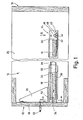
- 10 denotes a part of a housing in which, for example, a plurality of inserts 12 can be arranged horizontally displaceably in insertion compartments 14.
- inserts 12 can be arranged horizontally displaceably in insertion compartments 14.
- other types of supports for example drawers, could of course also be provided.
- the slide-in units have a slide-in base 16, on the front end of which a slide-in front plate 18 is arranged, which is fastened to the slide-in base 16 by means of brackets 20.
- 22 denotes a handle attached to the outside of the insert front panel.
- the insert shown is by means of a pair of pull-outs 24 on the opposite one another Side walls of the slot 14 guided easily displaceable.
- these pull-outs each have a pair of pull-out rails, namely a stationary pull-out rail 28 fastened to a side wall 26 and a pull-out rail 30 which is guided in a longitudinally movable manner thereon and carries the insert 12.
- the longitudinally movable pull-out rail is guided on the pull-out rail 28, for example by means of a roller body-mounted guide body 32.
- Z-shaped holding rails 34 are arranged along the side of the slide-in shelf 16 in cross section, which with one leg 36 engage under the slide-in shelf 16 and are screwed to it while it is being screwed rest with their other leg 38 on the top of the longitudinally movable pull-out rail 30.
- each pull-out 24 is assigned a locking member 40 at the rear end of the shelf 16, which can be locked on a stop 42 arranged on the pull-out rail 30.
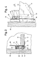
- the latching members are each formed by a spring tongue 44, which are fastened, for example, to the underside of the slide-in shelf and protrude beyond its rear end. At their free end, the spring tongues are equipped with an upwardly projecting locking lug 46 which, seen in the direction of insertion of the insert, has a contact surface 48 which extends obliquely upwards and backwards from below.
- This contact surface 48 is assigned an oblique contact surface 50 at the stop 42, which is preferably formed by a tongue bent out of the pull-out rail 30.
- the stop 42 protrudes so far in the direction of the opposite pull-out that the latching lug 46 with its contact surface 48 strikes this contact surface 50 when the insert is applied to the pull-outs or their pull-out rails 30.
- the lateral holding rails 34 of the shelf 16 are equipped in the region of their front end with an outwardly directed projection 52 in the form of a longitudinal bead, which in the movable pull-out rail 30 is accessible from the front end thereof slot-like longitudinal recess 54 is assigned.
- the projections 52 engage in these longitudinal recesses in a form-fitting manner, the insert on the pull-out rails 30 being fixed in the longitudinal direction thereof by the catches 46 of its catch members 40 engaging behind the stops 42 assigned to them.
- the insert 12 is to be removed from the pull-outs 24, for example for the purpose of cleaning it.
- This can be accomplished in a simple manner by first pulling the insert 12 a little out of the insert compartment 14 and then lifting it off with its front end from the movable pull-out rails, as shown in FIG. 3.
- This is possible despite the engagement of the crescent-like projections 52 in the longitudinal recesses 54 of the pull-out rails 30, because the latter can be deflected correspondingly far outwards when the feeder is raised by the projections 52.
- This inclination of the insert has the result that the detent 46 of the detent members 40 dips down relative to the stops 42 associated therewith (FIG. 5), so that the inclination of the insert causes it to be completely detached from the pull-outs 24.
- the insert can then be pulled out of the insert compartment 14 completely, the pull-out rails 30 being able to move out of the insert compartment 14 by the support rails 34 of the insert still resting on these pull-out rails with their rear ends.
- the attachment of the insert on the pull-outs 24 is just as simple in that the legs 38 of its holding rails 34 are initially to be placed with their rear ends on the pull-out pull-out rails 30. The insert can then be lowered so that it rests completely on the pull-out rails 30. However, it is also possible to first push it into the insertion compartment 14 in a slightly raised position shown in FIG. 5, the pull-out rails 30 in both cases initially moving together with the insertion into the insertion compartment for so long, until they have reached their insertion end position, which is defined by a stop (not shown in more detail).
- the construction described offers the essential advantage that the insert can be fixed on the pull-out rails 30 of the two pull-outs 24 relative to one another in any relative position can by placing the slide-in at least with its rear end on the pull-out rails and then pushing it into the slide-in compartment until it can be placed completely on the slide-in rails. These then move automatically when the slide-in is pushed further into their inner end position, after which the slide-in movement required for the slide-in locking is still to be carried out relative to the pull-out rails 30.
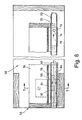
- a drawer 56 is displaceably guided within a drawer compartment 58 by means of pull-outs 60 and is releasably fastened on its pull-out pull-out rails 62 by latching.
- the drawer is latched in the form of a latching member 64 in the region of the front end of the longitudinally movable pull-out rail 62 in the form of a latching tongue 64, which is punched out of the outer U-leg 66 of a receptacle body 68 which is U-shaped in cross-section and which is provided with its other U-leg 70 is attached to the long side of the pull-out rail 62.
- a peg-shaped positioning stop 72 is arranged on the outside of the pull-out rail 62, against which a stop surface 74 of the drawer can be placed. This is formed on an extension piece 76, which is arranged on the long side of the drawer frame and protrudes on the underside thereof.
- the latching tongue 64 of the receiving body 68 of the pull-out rail 62 is assigned on the longitudinal side of the drawer frame 78 an extension 80 projecting downward therefrom and having a window-like latching recess 82.
- the extension piece 80 engages between the two U-legs 66, 70 of the receiving body 68, the in the direction of the U-leg 70 in Cross-section of concavely curved latching tongue 64 engages essentially in a form-fitting manner in the latching recess 82 of the extension piece 80.
- This locked position of the drawer can be seen in FIGS. 6 and 7.
- the free end edge 88 of the latching tongue 64 forms a stop edge which is adjacent to an end edge 90 of the latching recess 82.
- the end edge 90 will rest against the stop edge 88 of the latching tongue 64 and prevent the drawer from being pulled down by the latter after the pull-out rails 62 have reached their extended position.
- the front part of the drawer is to be lifted, a latching friction torque generated by the latching tongue 64 in cooperation with the lower longitudinal edge 92 of the latching recess 82 of the attachment being overcome and the drawer 56 being released by the latching tongues of both receiving bodies 88 of the pull-outs 60.
- the drawer can then be pulled out of the drawer compartment in the appropriate inclined position, the pull-out rails 62 moving outwards.
- the drawer To fix the drawer on the pull-out rails 62, the drawer must be placed on the latter and moved into the interior of the drawer compartment until the pull-out rails 62 have reached their end-of-insertion position, so that after a further relative displacement of the drawer, its stop faces 74 with the positioning stops 72 of the pull-out rails 62 come into contact and the latching tongues 64 snap into the latching recesses 82 of the extension pieces 80.
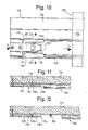
- FIG. 10 to 14 show a side wall 102 of a frame 100 to which the stationary pull-out rail 104 of a pull-out guide 106 is fastened by means of screws or the like, not shown.
- the latter also has a sliding pull-out rail 108 which e.g. is held longitudinally displaceably on the stationary pull-out rail 104 by means of bearing balls, likewise not shown and held in a ball cage.
- two pull-out guides 106 are to be provided for each support that can be pulled out of the frame 100, between which a drawer 110 forming the support is arranged.
- the side walls 112 of this drawer each have a longitudinal shoulder 114 with which the drawer rests on the pull-out rails 108 of the pull-out guides 106, as can be seen in FIG. 13.
- the displaceable pull-out rails 108 each have a projection 116 in the region of their front ends, which forms the first securing element of a latching connection according to the invention.
- this projection has a lower and an upper run-up surface 116 a and 116 b, respectively, which facilitate the making or releasing of the latching connection, as will be described in the following.
- a spring tongue 118 is fastened to the drawer 110 as a second securing element of the latching connection according to the invention, specifically according to the invention in such a way that a gap 120 is formed between the undeformed spring tongue and the adjacent drawer side wall 112, the width of which corresponds to the material thickness of the displaceable pull-out rail 108, as clearly shown in FIG Fig. 11 reveals.
- This spring tongue has on its side facing the drawer side wall 112 of its rear end a run-up surface 118 a and in front of this a pocket-like recess 118 b, which according to the invention is at least limited to the front and back and down and consequently a front stop edge 118 c, a rear stop edge 118 d and forms a lower boundary 118 e.
- the spring tongues 118 slide onto the projections 116 thanks to the run-up surfaces 118 a when the drawer 110 is pushed further into the frame 100, whereupon the projections 116 in engage the recesses 118 b.
- each of the projections 116 forms a pair of stops with the front stop edge 118 c and with the rear stop edge 118 d, which prevents longitudinal displacements of the drawer 110 relative to the displaceable pull-out rails 108.
- the latching connection can also be easily released by simply lifting the drawer, it being sufficient for the front part of the drawer stand out from the pull-out guides. Thanks to the lower ramp surface 116 a on the projection 116, it would of course also be possible to lock the drawer 110 with the sliding pull-out rails 108 in the opposite way to releasing the locking, but the method described at first is much simpler since one then aligns the two pull-out rails 108 can dispense with the drawer 110.
- the height of the spring tongue 118 corresponds to the clear distance between the upper and lower legs 104 a of the stationary pull-out rail 104 from one another, so that when the drawer 110 is installed and fully inserted, the spring tongue 118 fits into the U formed by the stationary pull-out rail 104 Profile engages, as can be seen in FIG. 13. In this way it can be achieved that e.g. Despite play in the pull-out guides, at least the front part of the drawer 110 always assumes a predetermined position relative to the frame 100 when fully inserted, since the drawer is positioned relative to the stationary pull-out rails 104 by the spring tongues 118.
- the spring tongue 118 has run-up surfaces 118 f at least at the bottom, but preferably also at the top.
- a particular advantage of the latching connection according to the invention can be seen in the fact that it is arranged between the pull-out rails of the pull-out guide, since both securing elements (spring tongue 118 and projection 116) lie between the pull-out rails 104, 108 even when the drawer is fully inserted.
- the invention therefore does not require any additional space, even though the securing element arranged on the drawer together with the stationary pull-out rail also forms a support device.
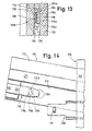
- FIGS. 15 and 16 shows how the latching connection according to the invention according to FIGS. 10 to 14 can advantageously be applied to plastic drawers which are on the sides, i.e. are double-walled in the side area of the so-called drawer frame, so that so-called adapters can be inserted into the drawer side walls from below or from the rear as usual, with the aid of which the drawers can be adapted to certain pull-out guides.
- plastic drawers are manufactured either by deep-drawing or injection molding, and the adapters are mostly plastic injection-molded parts.
- FIG. 15 transversely to the direction of displacement of a plastic drawer 200 reveals an outer side wall 202 and an inner side wall 204 of the drawer, which are intended to form a channel 206 which is open towards the bottom and rear.
- an adapter 208 is fastened in each case by means which are not shown but are customary (for example by gluing or by latching the lugs of one part into recesses in the other part), and according to the invention these adapters are in their Front areas molded spring tongues 210, which correspond to the spring tongues 118 of the embodiment of FIGS. 10 to 14.
Landscapes
- Drawers Of Furniture (AREA)
Claims (13)
Priority Applications (1)
| Application Number | Priority Date | Filing Date | Title |
|---|---|---|---|
| AT81103513T ATE14655T1 (de) | 1980-06-07 | 1981-05-08 | Auszugfuehrung fuer aus einem gestell ausziehbare traeger, wie schubladen oder dergleichen. |
Applications Claiming Priority (4)
| Application Number | Priority Date | Filing Date | Title |
|---|---|---|---|
| DE3021508 | 1980-06-07 | ||
| DE3021508 | 1980-06-07 | ||
| DE19813114809 DE3114809A1 (de) | 1980-06-07 | 1981-04-11 | Aufzugfuehrung fuer aus einem gestell ausziehbare traeger, wie schubladen o.dgl. |
| DE3114809 | 1981-04-11 |
Publications (2)
| Publication Number | Publication Date |
|---|---|
| EP0041616A1 EP0041616A1 (fr) | 1981-12-16 |
| EP0041616B1 true EP0041616B1 (fr) | 1985-08-07 |
Family
ID=25785896
Family Applications (1)
| Application Number | Title | Priority Date | Filing Date |
|---|---|---|---|
| EP81103513A Expired EP0041616B1 (fr) | 1980-06-07 | 1981-05-08 | Glissière télescopique pour support, tel que tiroirou similaire |
Country Status (6)
| Country | Link |
|---|---|
| EP (1) | EP0041616B1 (fr) |
| BE (1) | BE888952A (fr) |
| DE (2) | DE3114809A1 (fr) |
| DK (1) | DK154864C (fr) |
| FR (1) | FR2483757A1 (fr) |
| GB (1) | GB2081071B (fr) |
Cited By (1)
| Publication number | Priority date | Publication date | Assignee | Title |
|---|---|---|---|---|
| DE3822575A1 (de) * | 1987-07-02 | 1989-01-12 | Standard Praezision Gmbh | Behaeltnis mit zugglied und teleskopierbaren zuggliedfuehrungen |
Families Citing this family (18)
| Publication number | Priority date | Publication date | Assignee | Title |
|---|---|---|---|---|
| ATE15312T1 (de) * | 1982-04-21 | 1985-09-15 | Loh Kg Rittal Werk | Gestell mit mittels seitengleitfuehrungen verstellbaren kartenrahmen. |
| AT384535B (de) * | 1982-12-13 | 1987-11-25 | Blum Gmbh Julius | Ausziehfuehrungsgarnitur fuer schubladen od.dgl. |
| DE3324379C2 (de) * | 1983-07-06 | 1994-05-19 | Schock Metallwerk | Auszugführung für eine Schublade oder dergleichen |
| DE3347540A1 (de) * | 1983-12-30 | 1985-07-11 | Paul Hettich GmbH & Co, 4983 Kirchlengern | Schubkastenfuehrung |
| GB2196527A (en) * | 1986-10-31 | 1988-05-05 | G A Harvey Office Furniture Li | Filing units |
| DE3717359A1 (de) * | 1987-05-22 | 1988-12-08 | Schock Metallwerk | Auszugfuehrung mit ausrollsicherung |
| AT398265B (de) * | 1990-01-22 | 1994-11-25 | Blum Gmbh Julius | Befestigungsvorrichtung für die frontblende einer schublade |
| AT399446B (de) * | 1991-04-30 | 1995-05-26 | Blum Gmbh Julius | Montagebeschlag für schubladen |
| AT399808B (de) * | 1992-02-28 | 1995-07-25 | Blum Gmbh Julius | Schublade |
| DE9310582U1 (de) * | 1993-07-15 | 1993-09-23 | Hettich Paul Gmbh & Co | Rasteinrichtung fuer schubkaesten o.dgl. |
| DE4433577A1 (de) * | 1994-09-21 | 1996-03-28 | Hettich Paul Gmbh & Co | Möbelauszugsteil |
| US5671988A (en) * | 1995-05-24 | 1997-09-30 | Waterloo Furniture Components, Ltd. | Drawer slide latch |
| NL1002123C2 (nl) * | 1996-01-18 | 1997-07-22 | Thomas Regout B V | Samenstel van lade-elementen, draag- en looprails en een kastombouw. |
| DE19749999A1 (de) * | 1997-11-12 | 1999-05-27 | Formaplan Holzwerkstoffe Gmbh | Auszugsbeschlag für Schubladen |
| US6435636B1 (en) * | 2000-06-15 | 2002-08-20 | Compx International Inc. | Drawer slide cushion end stop bumper construction |
| AT506879B1 (de) | 2008-06-10 | 2011-07-15 | Blum Gmbh Julius | Vorrichtung zum lösbaren kuppeln einer schublade mit einer schiene einer schubladenausziehführung |
| AT11720U3 (de) * | 2010-09-16 | 2011-12-15 | Mediadent Medizinisch Tech Produktions Und Vertriebs Gmbh | Adapter für ein ladensystem |
| DE102011051126A1 (de) * | 2011-06-17 | 2012-12-20 | Schock Metallwerk Gmbh | Auszugführung und Auszugsvorrichtung |
Family Cites Families (7)
| Publication number | Priority date | Publication date | Assignee | Title |
|---|---|---|---|---|
| US3177047A (en) * | 1962-11-19 | 1965-04-06 | Mutchnik Henry | Drawer guide assemblies |
| NL137870C (fr) * | 1967-08-03 | 1900-01-01 | ||
| US3650578A (en) * | 1969-09-10 | 1972-03-21 | Instrument Systems Corp | Quick disconnect slide structure |
| US3771849A (en) * | 1972-03-06 | 1973-11-13 | Standard Precision Inc | Bayonet-mounting means for sliding drawers |
| DE2456520A1 (de) * | 1974-11-29 | 1976-08-12 | Hettich Paul & Co | Kugelgelagerte ausziehfuehrung fuer schubkaesten od.dgl. |
| DE2745281B2 (de) * | 1977-10-07 | 1980-04-24 | Bbp-Kunststoffwerk Marbach Baier & Co, 7142 Marbach | Schubkastenführung |
| DE2821101C3 (de) * | 1978-05-13 | 1980-10-16 | Schock & Co Gmbh, 7060 Schorndorf | Auszugführung für in einem Gestell gehaltene Schubladen o.dgl |
-
1981
- 1981-04-11 DE DE19813114809 patent/DE3114809A1/de not_active Withdrawn
- 1981-05-08 EP EP81103513A patent/EP0041616B1/fr not_active Expired
- 1981-05-08 DE DE8181103513T patent/DE3171681D1/de not_active Expired
- 1981-05-25 BE BE0/204895A patent/BE888952A/fr not_active IP Right Cessation
- 1981-06-04 DK DK246581A patent/DK154864C/da not_active IP Right Cessation
- 1981-06-05 FR FR8111244A patent/FR2483757A1/fr active Granted
- 1981-06-08 GB GB8117445A patent/GB2081071B/en not_active Expired
Cited By (1)
| Publication number | Priority date | Publication date | Assignee | Title |
|---|---|---|---|---|
| DE3822575A1 (de) * | 1987-07-02 | 1989-01-12 | Standard Praezision Gmbh | Behaeltnis mit zugglied und teleskopierbaren zuggliedfuehrungen |
Also Published As
| Publication number | Publication date |
|---|---|
| GB2081071A (en) | 1982-02-17 |
| DK154864B (da) | 1989-01-02 |
| DK154864C (da) | 1989-05-16 |
| FR2483757B1 (fr) | 1985-01-11 |
| EP0041616A1 (fr) | 1981-12-16 |
| DK246581A (da) | 1981-12-08 |
| BE888952A (fr) | 1981-09-16 |
| DE3171681D1 (en) | 1985-09-12 |
| DE3114809A1 (de) | 1982-06-03 |
| GB2081071B (en) | 1984-04-18 |
| FR2483757A1 (fr) | 1981-12-11 |
Similar Documents
| Publication | Publication Date | Title |
|---|---|---|
| EP0041616B1 (fr) | Glissière télescopique pour support, tel que tiroirou similaire | |
| EP0421458B1 (fr) | Tiroir | |
| EP0011675B1 (fr) | Glissière pour tiroirs ou similaires | |
| EP0695523B1 (fr) | Dispositif pour la fixation d'une glissière pour tiroir | |
| DE3832701A1 (de) | Befestigungsanordnung fuer die fuehrungsschiene einer ausziehfuehrung | |
| WO1992013473A1 (fr) | Guide de sortie pour tiroirs | |
| WO1998023138A2 (fr) | Armoire de distribution comportant une plaque de montage | |
| DE102010022203A1 (de) | Tür eines Kühl- und/oder Gefriergerätes | |
| EP0818163B2 (fr) | Coulisse de tiroir | |
| DE3149310A1 (de) | Vorrichtung und verfahren zur befestigung von elektrischen installationsgeraeten auf normprofilschienen, insbesondere auf hutprofilschienen | |
| EP1513429A1 (fr) | Ensemble pour relier un encadrement de tiroir au fond de tiroir | |
| EP0306701B1 (fr) | Insert pour tiroirs de meuble | |
| DE3135222C2 (fr) | ||
| EP3166444A1 (fr) | Guidage télescopique pour une partie de meuble mobile | |
| DE10237138A1 (de) | Absteller für ein Kältegerät | |
| EP0639687B1 (fr) | Glissière | |
| DE10022084C2 (de) | Laufschiene für Schubkästen | |
| AT395809B (de) | Ausziehfuehrung fuer schubladen u.dgl. | |
| DE4304074C1 (de) | Kühlgerät, insbesondere Haushalt-Kühlschrank | |
| AT398515B (de) | Beschlag zur lösbaren halterung | |
| DE102015203436A1 (de) | Dunstabzugshaube mit Auszugskörper | |
| DE10318781A1 (de) | Auszugführung | |
| DE8307357U1 (de) | Teleskopauszug mit kugelfuehrung | |
| AT399447B (de) | Ausziehführungsgarnitur für schubladen | |
| EP0523424A1 (fr) | Dispositif de guidage pour tiroir |
Legal Events
| Date | Code | Title | Description |
|---|---|---|---|
| PUAI | Public reference made under article 153(3) epc to a published international application that has entered the european phase |
Free format text: ORIGINAL CODE: 0009012 |
|
| AK | Designated contracting states |
Designated state(s): AT CH DE IT NL SE |
|
| ITCL | It: translation for ep claims filed |
Representative=s name: BARZANO' E ZANARDO MILANO S.P.A. |
|
| 17P | Request for examination filed |
Effective date: 19820612 |
|
| ITF | It: translation for a ep patent filed |
Owner name: BARZANO' E ZANARDO MILANO S.P.A. |
|
| GRAA | (expected) grant |
Free format text: ORIGINAL CODE: 0009210 |
|
| AK | Designated contracting states |
Designated state(s): AT CH DE IT LI NL SE |
|
| REF | Corresponds to: |
Ref document number: 14655 Country of ref document: AT Date of ref document: 19850815 Kind code of ref document: T |
|
| REF | Corresponds to: |
Ref document number: 3171681 Country of ref document: DE Date of ref document: 19850912 |
|
| PLBE | No opposition filed within time limit |
Free format text: ORIGINAL CODE: 0009261 |
|
| STAA | Information on the status of an ep patent application or granted ep patent |
Free format text: STATUS: NO OPPOSITION FILED WITHIN TIME LIMIT |
|
| 26N | No opposition filed | ||
| ITTA | It: last paid annual fee | ||
| EAL | Se: european patent in force in sweden |
Ref document number: 81103513.8 |
|
| PGFP | Annual fee paid to national office [announced via postgrant information from national office to epo] |
Ref country code: SE Payment date: 20000406 Year of fee payment: 20 |
|
| PGFP | Annual fee paid to national office [announced via postgrant information from national office to epo] |
Ref country code: AT Payment date: 20000518 Year of fee payment: 20 |
|
| PGFP | Annual fee paid to national office [announced via postgrant information from national office to epo] |
Ref country code: NL Payment date: 20000531 Year of fee payment: 20 Ref country code: CH Payment date: 20000531 Year of fee payment: 20 |
|
| PGFP | Annual fee paid to national office [announced via postgrant information from national office to epo] |
Ref country code: DE Payment date: 20000621 Year of fee payment: 20 |
|
| PG25 | Lapsed in a contracting state [announced via postgrant information from national office to epo] |
Ref country code: LI Free format text: LAPSE BECAUSE OF EXPIRATION OF PROTECTION Effective date: 20010507 Ref country code: CH Free format text: LAPSE BECAUSE OF EXPIRATION OF PROTECTION Effective date: 20010507 |
|
| PG25 | Lapsed in a contracting state [announced via postgrant information from national office to epo] |
Ref country code: NL Free format text: LAPSE BECAUSE OF EXPIRATION OF PROTECTION Effective date: 20010508 Ref country code: AT Free format text: LAPSE BECAUSE OF EXPIRATION OF PROTECTION Effective date: 20010508 |
|
| PG25 | Lapsed in a contracting state [announced via postgrant information from national office to epo] |
Ref country code: SE Free format text: THE PATENT HAS BEEN ANNULLED BY A DECISION OF A NATIONAL AUTHORITY Effective date: 20010530 |
|
| REG | Reference to a national code |
Ref country code: CH Ref legal event code: PL |
|
| NLV7 | Nl: ceased due to reaching the maximum lifetime of a patent |
Effective date: 20010508 |
|
| EUG | Se: european patent has lapsed |
Ref document number: 81103513.8 |