EP0040260B1 - Transistor-Zündschaltung - Google Patents
Transistor-Zündschaltung Download PDFInfo
- Publication number
- EP0040260B1 EP0040260B1 EP80105536A EP80105536A EP0040260B1 EP 0040260 B1 EP0040260 B1 EP 0040260B1 EP 80105536 A EP80105536 A EP 80105536A EP 80105536 A EP80105536 A EP 80105536A EP 0040260 B1 EP0040260 B1 EP 0040260B1
- Authority
- EP
- European Patent Office
- Prior art keywords
- transistor
- zener diode
- voltage
- voltage divider
- resistor
- Prior art date
- Legal status (The legal status is an assumption and is not a legal conclusion. Google has not performed a legal analysis and makes no representation as to the accuracy of the status listed.)
- Expired
Links
Images
Classifications
-
- H—ELECTRICITY
- H03—ELECTRONIC CIRCUITRY
- H03K—PULSE TECHNIQUE
- H03K17/00—Electronic switching or gating, i.e. not by contact-making and –breaking
- H03K17/14—Modifications for compensating variations of physical values, e.g. of temperature
-
- F—MECHANICAL ENGINEERING; LIGHTING; HEATING; WEAPONS; BLASTING
- F02—COMBUSTION ENGINES; HOT-GAS OR COMBUSTION-PRODUCT ENGINE PLANTS
- F02P—IGNITION, OTHER THAN COMPRESSION IGNITION, FOR INTERNAL-COMBUSTION ENGINES; TESTING OF IGNITION TIMING IN COMPRESSION-IGNITION ENGINES
- F02P3/00—Other installations
- F02P3/02—Other installations having inductive energy storage, e.g. arrangements of induction coils
- F02P3/04—Layout of circuits
- F02P3/055—Layout of circuits with protective means to prevent damage to the circuit, e.g. semiconductor devices or the ignition coil
- F02P3/0552—Opening or closing the primary coil circuit with semiconductor devices
-
- H—ELECTRICITY
- H03—ELECTRONIC CIRCUITRY
- H03K—PULSE TECHNIQUE
- H03K17/00—Electronic switching or gating, i.e. not by contact-making and –breaking
- H03K17/08—Modifications for protecting switching circuit against overcurrent or overvoltage
- H03K17/082—Modifications for protecting switching circuit against overcurrent or overvoltage by feedback from the output to the control circuit
- H03K17/0826—Modifications for protecting switching circuit against overcurrent or overvoltage by feedback from the output to the control circuit in bipolar transistor switches
Definitions
- the invention relates to a transistor ignition circuit according to the preamble of the first claim.
- a known transistor ignition circuit of this type (FR-A No. 2238846), the collector-emitter path of a transistor is connected in series with the primary winding of an ignition coil. Parallel to the transistor is a voltage divider, which is formed from the series connection of two ohmic resistors. A zener diode lies between the center of the voltage divider and the base of a further transistor, the base of this further transistor forming a circuit input for signals from an upstream pulse shaping stage. The further transistor is connected to the base of the first transistor via an emitter coupling. In this arrangement, a control signal via the zener diode is fed back to the circuit input via the voltage divider, which control signal limits the flashback voltage that occurs at the first transistor and is caused by the ignition coil.
- the flashback voltage is temperature-dependent.
- the limitation of the flashback voltage must therefore be set to a value which, under the most unfavorable conditions, does not exceed the limit voltage permitted at the transistor.
- the object of the invention is to take measures in a transistor ignition circuit according to the preamble of the first claim, by means of which the flashback voltage occurring at the primary winding of the ignition coil is kept constant within narrow limits within a wide temperature range.
- the temperature response of the zener diode which influences the flashback voltage, is counteracted by the temperature response of one of the resistors in the voltage divider. This limits the flashback voltage to a relatively narrow and constant value over a wide temperature range.
- an adaptation to the temperature response of the Zener diode can be achieved as an advantage by choosing the thick-film resistance paste with the desired resistance value and temperature response.
- the resistance connected to the ground potential can be adjustable in order to be able to adapt the flashback voltage to the respective values of the selected transistor.
- the zener diode can be connected directly to the base of the transistor to be protected, so that the returned limiting signal acts on the base of this transistor without any further intermediate components.
- the temperature coefficient of a standard 150 V Zener diode is (+9 to +13) -10 -4 K -1 , so that the temperature coefficient of the voltage divider must be taken into account in order to achieve a required voltage range between 360 V and 385 V.
- the resistor R 1 must have a temperature coefficient opposite the Zener diode, or the resistor R 2 must conform.
Landscapes
- Engineering & Computer Science (AREA)
- Chemical & Material Sciences (AREA)
- Combustion & Propulsion (AREA)
- Mechanical Engineering (AREA)
- General Engineering & Computer Science (AREA)
- Ignition Installations For Internal Combustion Engines (AREA)
- Coils Or Transformers For Communication (AREA)
Description
- Die Erfindung betrifft eine Transistorzündschaltung gemäss dem Oberbegriff des ersten Patentanspruchs.
- Bei einer bekannten Transistorzündschaltung dieser Art (FR-A Nr. 2238846) ist in Serie mit der Primärwicklung einer Zündspule die Kollektoremitterstrecke eines Transistors geschaltet. Parallel zum Transistor liegt ein Spannungsteiler, der aus der Reihenschaltung von zwei ohmschen Widerständen gebildet ist. Zwischen dem Mittelpunkt des Spannungsteilers und der Basis eines weiteren Transistors liegt eine Zenerdiode, wobei die Basis dieses weiteren Transistors einen Schaltungseingang für Signale aus einer vorgeschalteten lmpulsformerstufe bildet. Der weitere Transistor ist über eine Emitterkopplung mit der Basis des ersten Transistors verbunden. Bei dieser Anordnung wird über den Spannungsteiler ein Steuersignal über die Zenerdiode auf den Schaltungseingang zurückgeführt, das die am ersten Transistor auftretende, von der Zündspule verursachte Rückschlagspannung begrenzt. Es zeigt sich jedoch, dass bei so aufgebauten Transistorzündschaltungen die Rückschlagspannung temperaturabhängig ist. Die Begrenzung der Rückschlagspannung muss daher auf einen Wert eingestellt sein, der unter den ungünstigsten Bedingungen die am Transistor zulässige Grenzspannung nicht überschreitet.
- Der Erfindung liegt die Aufgabe zugrunde, bei einer Transistorzündschaltung gemäss dem Oberbegriff des ersten Anspruchs Massnahmen zu treffen, durch welche die an der Primärwicklung der Zündspule auftretende Rückschlagspannung in einem weiten Temperaturbereich in engen Grenzen konstant gehalten wird.
- Die Lösung dieser Aufgabe erfolgt gemäss der Erfindung durch die kennzeichnenden Merkmale des ersten Anspruchs.
- Gemäss der Erfindung wird dem die Rückschlagspannung beeinflussenden Temperaturgang der Zenerdiode durch den Temperaturgang eines der Widerstände im Spannungsteiler entgegengewirkt. Dadurch wird die Rückschlagspannung in einem weiten Temperaturbereich auf einen relativ engen und konstanten Wert begrenzt.
- Bei der Verwendung eines Schichtwiderstandes kann als Vorteil durch die Wahl der Dickschicht-Widerstandspaste mit dem gewünschten Widerstandswert und Temperaturgang eine Anpassung an den Temperaturgang der Zenerdiode erreicht werden. Dabei kann der mit dem Massenpotential verbundene Widerstand einstellbar sein, um die Rückschlagspannung den jeweiligen Werten des gewählten Transistors anpassen zu können. Daneben kann die Zenerdiode unmittelbar an die Basis des zu schützenden Transistors angeschaltet werden, so dass das zurückgeführte Begrenzungssignal ohne weitere zwischengeschaltete Bauelemente auf die Basis dieses Transistors wirkt.
- Ein Ausführungsbeispiel der Erfindung ist in der Zeichnung dargestellt:
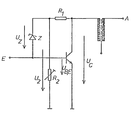
- Zwischen der Primärwicklung und dem Massenpotential ist ein Transistor zu einem ohmschen Spannungsteiler R1, R2 parallelgeschaltet, wobei der Widerstand R2 zur Einstellung der Rückschlagspannungsbegrenzung dient. Zwischen der den Schaltungseingang E bildenden Basis des Transistors und dem Mittelpunkt des Spannungsteilers R1, R2 liegt die Zenerdiode Z. Wenn die am Widerstand R2 abfallende Spannung U2, die sich aus dem Teilerverhältnis R, zu R2 und der Rückschlagspannung am Kollektor Uc ergibt, die Zenerspannung Uz und die Spannung UBE überschreitet, wird die Zenerdiode leitend und steuert den Transistor durch, d.h. die Rückschlagspannung wird begrenzt. Durch den Temperaturkoeffizienten der Spannung der Zenerdiode ändert sich somit auch die Rückschlagspannung am Kollektor Uc. Um diese Änderung der Rückschlagspannung zu vermeiden, wird der Temperaturkoeffizient des Widerstandes R1 oder des Widerstandes R2 derart gewählt, dass die Zenerspannung Uz über einen weiteren Bereich temperaturkompensiert und die Rückschlagspannung über einen weiten Temperaturbereich eng begrenzt wird.
- Bei einem Ausführungsbeispiel soll die Kollektorspannung Uc zwischen 360 V und 385 V im Temperaturbereich zwischen -28 und +115°C liegen. Bei Wahl des Transistors mit UBE=2 V und einer Zenerdiode mit Uz=150 V ergibt sich bei

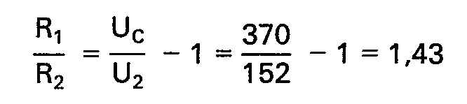
- Ohne Berücksichtigung eines Temperaturganges des Spannungsteilers errechnet sich der Temperaturkoeffizient der Zenerdiode zu


- Der Temperaturkoeffizient einer handelsüblichen 150 V Zenerdiode liegt jedoch bei (+9 bis +13) -10-4 K-1, so dass der Temperaturkoeffizient des Spannungsteilers berücksichtigt werden muss, um zu einem geforderten Spannungsbereich zwischen 360 V und 385 V zu gelangen.
- Mit einer Zenerdiode Uz=150 V und TK,Z= +9 · 10-4 K-1 und einem Transistor mit UB,E=2 V und TK.BE=-5 · 10-3. K-1 gilt
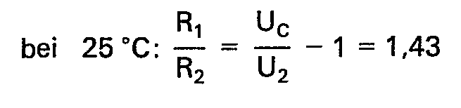


- Erfindungsgemässsoll Uckonstant sein, woraus folgt:

- Mit R2 = konstant, ergibt sich R2 25 = R2 115 und
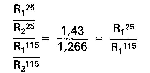


- Der Widerstand R1 muss einen der Zenerdiode entgegengesetzten Temperaturkoeffizienten besitzen, bzw. der Widerstand R2 einen konformen.
Claims (4)
Applications Claiming Priority (2)
| Application Number | Priority Date | Filing Date | Title |
|---|---|---|---|
| DE3019162A DE3019162C2 (de) | 1980-05-20 | 1980-05-20 | Transistor-Zündschaltung |
| DE3019162 | 1980-05-20 |
Publications (2)
| Publication Number | Publication Date |
|---|---|
| EP0040260A1 EP0040260A1 (de) | 1981-11-25 |
| EP0040260B1 true EP0040260B1 (de) | 1984-01-25 |
Family
ID=6102825
Family Applications (1)
| Application Number | Title | Priority Date | Filing Date |
|---|---|---|---|
| EP80105536A Expired EP0040260B1 (de) | 1980-05-20 | 1980-09-16 | Transistor-Zündschaltung |
Country Status (3)
| Country | Link |
|---|---|
| US (1) | US4413192A (de) |
| EP (1) | EP0040260B1 (de) |
| DE (1) | DE3019162C2 (de) |
Families Citing this family (6)
| Publication number | Priority date | Publication date | Assignee | Title |
|---|---|---|---|---|
| DE3344476A1 (de) * | 1983-12-08 | 1985-06-20 | Siemens AG, 1000 Berlin und 8000 München | Schaltungsanordnung zum ansteuern eines thyristors mit licht |
| JP2796209B2 (ja) * | 1992-01-17 | 1998-09-10 | 株式会社日立製作所 | 内燃機関用電子配電点火装置 |
| DE4315999A1 (de) * | 1992-10-02 | 1994-04-07 | Bosch Gmbh Robert | Zündanlage für Brennkraftmaschinen |
| US5446385A (en) * | 1992-10-02 | 1995-08-29 | Robert Bosch Gmbh | Ignition system for internal combustion engines |
| DE69527201D1 (de) * | 1995-07-31 | 2002-08-01 | St Microelectronics Srl | Integrierte Schaltung zur Spannungsbegrenzung |
| EP1018804A1 (de) * | 1999-01-05 | 2000-07-12 | Motorola, Inc. | Oszillator |
Citations (2)
| Publication number | Priority date | Publication date | Assignee | Title |
|---|---|---|---|---|
| US3710131A (en) * | 1971-01-08 | 1973-01-09 | Lumenition Ltd | Transistorized ignition systems |
| FR2238846A1 (en) * | 1973-07-28 | 1975-02-21 | Emihus Microcomponents Ltd | IC engine high tension ignition system - produces dwell impulses which are independent of engine speed to charge and discharge the ignition capacitor |
Family Cites Families (11)
| Publication number | Priority date | Publication date | Assignee | Title |
|---|---|---|---|---|
| DE1152139B (de) * | 1962-02-28 | 1963-08-01 | Graetz Kommanditgesellschaft | Schaltungsanordnung zur Stabilisierung der Ausgangsspannung einer Transistor-Horizontal-Ablenkstufe |
| DE1538440B2 (de) * | 1966-11-23 | 1972-03-16 | Deutsche Itt Industries Gmbh, 7800 Freiburg | Schaltungsanordnung zur gleichspannungsstabilisierung nach art einer z diode |
| GB1204882A (en) * | 1967-02-06 | 1970-09-09 | Lucas Industries Ltd | Voltage regulators for use in battery charging systems |
| NL6806969A (de) * | 1968-05-17 | 1969-05-27 | ||
| US3605713A (en) * | 1970-05-18 | 1971-09-20 | Gen Motors Corp | Internal combustion engine ignition system |
| DE2339896B2 (de) * | 1973-08-07 | 1977-12-08 | Robert Bosch Gmbh, 7000 Stuttgart | Zuendeinrichtung fuer brennkraftmaschinen |
| US3933141A (en) * | 1974-03-07 | 1976-01-20 | Motorola, Inc. | Zero crossing circuit for electronic ignition system |
| DE2454690A1 (de) * | 1974-11-19 | 1976-05-26 | Oswald Dipl Ing Dr Bell | Elektronische zuendschaltung |
| FR2295249A1 (fr) * | 1974-12-18 | 1976-07-16 | Ducellier & Cie | Dispositif d'allumage electronique pour vehicules automobiles equipes d'un moteur a allumage commande |
| DE2823788A1 (de) * | 1978-05-31 | 1979-12-06 | Bosch Gmbh Robert | Zuendanlage fuer eine brennkraftmaschine |
| IT1110163B (it) * | 1978-07-26 | 1985-12-23 | Ates Componenti Elettron | Circuito di blocco della tensione di ritraccia |
-
1980
- 1980-05-20 DE DE3019162A patent/DE3019162C2/de not_active Expired
- 1980-09-16 EP EP80105536A patent/EP0040260B1/de not_active Expired
-
1981
- 1981-05-13 US US06/263,101 patent/US4413192A/en not_active Expired - Fee Related
Patent Citations (2)
| Publication number | Priority date | Publication date | Assignee | Title |
|---|---|---|---|---|
| US3710131A (en) * | 1971-01-08 | 1973-01-09 | Lumenition Ltd | Transistorized ignition systems |
| FR2238846A1 (en) * | 1973-07-28 | 1975-02-21 | Emihus Microcomponents Ltd | IC engine high tension ignition system - produces dwell impulses which are independent of engine speed to charge and discharge the ignition capacitor |
Also Published As
| Publication number | Publication date |
|---|---|
| DE3019162A1 (de) | 1981-11-26 |
| DE3019162C2 (de) | 1985-11-07 |
| US4413192A (en) | 1983-11-01 |
| EP0040260A1 (de) | 1981-11-25 |
Similar Documents
| Publication | Publication Date | Title |
|---|---|---|
| DE3225822C2 (de) | ||
| EP0160836B1 (de) | Temperatursensor | |
| DE1110286B (de) | Elektronische, als Zweipol ausgebildete Anordnung zur Konstanthaltung eines Gleichstromes | |
| DE3132257A1 (de) | Schutzschaltung fuer einen feldeffekttransistor in einem laststromkreis | |
| DE2944988C2 (de) | Ladungsverstärker-Schaltung | |
| EP0040260A1 (de) | Transistor-Zündschaltung | |
| EP0292804B1 (de) | Schaltungsanordnung zur potentialfreien Erfassung von binären Signalen | |
| DE3303945C2 (de) | Schaltung zur temperaturkompensierenden Stromversorgung eines Hallgenerators | |
| DE2148437C3 (de) | Schaltungsanordnung zur Verbesserung der Kurzschlußfestigkeit von Schaltkreisen vom Typ der Langsamen störsicheren Logik | |
| DE2827868A1 (de) | Triggerverstaerker | |
| DE3405599C2 (de) | ||
| DE2800807C2 (de) | Schaltungsanordnung zur Abnahme und Formung der von einer Zündeinrichtung für Brennkraftmaschinen ausgehenden Signale | |
| DE2758758B2 (de) | Nichtlineare Funktionsschaltung | |
| DE71366T1 (de) | Lampen-betriebsschaltung. | |
| DE2507128C2 (de) | Schaltungsanordnung zur Gewinnung einer temperaturkompensierten Gleichspannung | |
| DE1176249B (de) | Spannungsueberwachungs- und Kurzschliess-vorrichtung | |
| DE3246144C2 (de) | Schaltungsanordnung zur Stromkonstanthaltung | |
| EP0074919B1 (de) | Schaltungsanordnung mit einem Messumformer, insbesondere mit einem Halbleiter-Druckaufnehmer | |
| DE1513126A1 (de) | Spannungsregler | |
| EP0103768A1 (de) | Stromspiegelschaltung | |
| DE1947467A1 (de) | Elektronische Schaltungsanordnung fuer Uhren und andere zeithaltende Geraete mit beliebigem Magnetsystem | |
| DE1213477B (de) | Induktiv rueckgekoppelter monostabiler Multivibrator | |
| AT220234B (de) | Schaltung zur Erzeugung eines einer Impulsfrequenz proportionalen Stromes | |
| DE1275117B (de) | Transistorschaltung zur UEberwachung von Gleichspannungen und Spannungswaechter unter Verwendung dieser Schaltung | |
| DE1930752C3 (de) | Verfahren und Vorrichtung zur Einstellung und Kontrolle eines elektrischen Grenzwertmelders |
Legal Events
| Date | Code | Title | Description |
|---|---|---|---|
| PUAI | Public reference made under article 153(3) epc to a published international application that has entered the european phase |
Free format text: ORIGINAL CODE: 0009012 |
|
| AK | Designated contracting states |
Designated state(s): FR GB IT SE |
|
| 17P | Request for examination filed |
Effective date: 19811026 |
|
| ITF | It: translation for a ep patent filed | ||
| GRAA | (expected) grant |
Free format text: ORIGINAL CODE: 0009210 |
|
| AK | Designated contracting states |
Designated state(s): FR GB IT SE |
|
| ET | Fr: translation filed | ||
| RAP2 | Party data changed (patent owner data changed or rights of a patent transferred) |
Owner name: TELEFUNKEN ELECTRONIC GMBH |
|
| PGFP | Annual fee paid to national office [announced via postgrant information from national office to epo] |
Ref country code: FR Payment date: 19840926 Year of fee payment: 5 |
|
| PLBE | No opposition filed within time limit |
Free format text: ORIGINAL CODE: 0009261 |
|
| STAA | Information on the status of an ep patent application or granted ep patent |
Free format text: STATUS: NO OPPOSITION FILED WITHIN TIME LIMIT |
|
| PGFP | Annual fee paid to national office [announced via postgrant information from national office to epo] |
Ref country code: SE Payment date: 19841231 Year of fee payment: 5 |
|
| 26N | No opposition filed | ||
| PG25 | Lapsed in a contracting state [announced via postgrant information from national office to epo] |
Ref country code: SE Effective date: 19870917 |
|
| PG25 | Lapsed in a contracting state [announced via postgrant information from national office to epo] |
Ref country code: GB Effective date: 19880916 |
|
| PG25 | Lapsed in a contracting state [announced via postgrant information from national office to epo] |
Ref country code: FR Free format text: LAPSE BECAUSE OF NON-PAYMENT OF DUE FEES Effective date: 19890531 |
|
| GBPC | Gb: european patent ceased through non-payment of renewal fee | ||
| REG | Reference to a national code |
Ref country code: FR Ref legal event code: ST |
|
| EUG | Se: european patent has lapsed |
Ref document number: 80105536.9 Effective date: 19880906 |