EP0039286A1 - Landwirtschaftliche Maschine zum Wenden, Schwaden, Verstreuen und Ausbreiten - Google Patents
Landwirtschaftliche Maschine zum Wenden, Schwaden, Verstreuen und Ausbreiten Download PDFInfo
- Publication number
- EP0039286A1 EP0039286A1 EP81400645A EP81400645A EP0039286A1 EP 0039286 A1 EP0039286 A1 EP 0039286A1 EP 81400645 A EP81400645 A EP 81400645A EP 81400645 A EP81400645 A EP 81400645A EP 0039286 A1 EP0039286 A1 EP 0039286A1
- Authority
- EP
- European Patent Office
- Prior art keywords
- machine according
- machine
- nozzles
- ground
- plate
- Prior art date
- Legal status (The legal status is an assumption and is not a legal conclusion. Google has not performed a legal analysis and makes no representation as to the accuracy of the status listed.)
- Withdrawn
Links
Images

Classifications
-
- A—HUMAN NECESSITIES
- A01—AGRICULTURE; FORESTRY; ANIMAL HUSBANDRY; HUNTING; TRAPPING; FISHING
- A01D—HARVESTING; MOWING
- A01D57/00—Delivering mechanisms for harvesters or mowers
- A01D57/01—Devices for leading crops to the mowing apparatus
- A01D57/10—Devices for leading crops to the mowing apparatus using fans
-
- A—HUMAN NECESSITIES
- A01—AGRICULTURE; FORESTRY; ANIMAL HUSBANDRY; HUNTING; TRAPPING; FISHING
- A01D—HARVESTING; MOWING
- A01D89/00—Pick-ups for loaders, chaff-cutters, balers, field-threshers, or the like, i.e. attachments for picking-up hay or the like field crops
Definitions
- the invention relates to an agricultural machine with wheels, towed, for wilting, swathing, spreading or spreading fodder or other plant material on the ground.
- the present invention aims to avoid rough handling of the material collected (fodder, straw, reeds, etc.) to maintain the quality of the fodder as much as possible.
- a tedder-swather according to the present invention comprises a tray, a pick-up for picking up the forage on the ground and depositing it on the tray and means for creating air jets. suitably oriented to chase the fodder deposited on the pan by the collector.
- the pickup can be of a type known per se, used in particular for feeding feed presses.
- pick-ups which include a rotor whose axis of rotation is arranged along the length of the machine, transverse to the direction of movement of the machine.
- This rotor driven in rotation on itself from the wheels of the machine or from the power take-off of the tractor, comprises longitudinal bars which can pivot on themselves during the rotation of the rotor; the pivoting of a bar is controlled for example by a fixed cam on the machine and against which moves a roller connected to the bar by a lever.
- the bar carries a series of fingers distributed along the bar in vertical planes perpendicular to the bar and the cam is chosen so that the end of each finger under the effect of the rotation of the rotor and the pivoting of the bar describes an appropriate curve, for example an approximately elliptical curve, passing through positions where the finger picks up forage, raises the forage, deposits the forage on the pan, then lowers, retracts under the platform, picks up new fodder, etc.
- an appropriate curve for example an approximately elliptical curve
- blowers have already been proposed to use blowers in various agricultural machines and it has even been proposed to combine blowers with a collection device, as described for example in Belgian patent n ° 485 672, but these machines do not realize the combination of the present invention and do not constitute tedders.
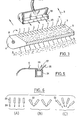
- the machine ( Figures 1 to 3) comprises an elongated frame 1 mounted on wheels 2 and able to be towed.
- the tractor or the device which cooperates with the three-point hitching system of a tractor to hang the machine behind the tractor so that it is arranged transversely to the direction is not shown in the figures. advancement 3 of the tractor.
- the chassis 1 has lateral flanges 4 connected by a longitudinal casing open below and at the rear.
- the top wall 5 of the casing constitutes a preferably horizontal plate and the front wall 6 of the casing has parallel vertical slots 7 which extend on the top wall. These slots are distributed along the length of the machine so that the housing forms like a curved comb.
- a longitudinal shaft 8 rotatably mounted in the side flanges.
- This rotation is ensured by the wheels of the machine connected to the shaft by any suitable transmission (not shown) or is ensured by an independent control, for example from the PTO of the tractor.
- the shaft carries two discs on which are pivotally mounted longitudinal bars which each carry a series of fingers arranged to pass through said slots when the rotor rotates. Only one finger has been represented in FIG. 1.
- each bar on the one hand is driven in rotation around the shaft 8 and, on the other hand, pivots on itself.
- This pivoting is controlled by a cam 12 fixed to one of the flanges and against which rolls a roller 13 mounted at the end of a lever 14 fixed to the bar.
- the roller is kept in pressure against the cam by any suitable means.
- the pebble is held captive by a channel 15 around the cam.
- the cam is designed so that the end of each finger describes in a vertical plane parallel to the direction of advance of the machine, a course generally generally elliptical during which the finger passes close to the ground, picks up the forage and the climbs onto the machine platform, the finger then retracts through the slots in the platform and descends to the ground to pick up forage again, etc.
- the descent can be vertical.
- the course can be other than elliptical, for example it can be circular.
- the invention is not limited to a particular form of route; generally, the shape of the tray is adapted to that of the path of the fingers to ensure correct placement on the tray of materials picked up on the ground by the fingers.
- the finger is preferably given a special shape designed to facilitate the release of the forage on the pan.
- the free end of the finger has the shape of a drawn Z.
- the finger 11 is constituted by a rod 16 whose rear end or fixing end 17 is bent to form a spring and whose front end 18 or pick-up end is straight but offset and parallel with respect to the rod , this end being connected to the rod by an intermediate part 19 sloping upwards towards the front.
- the supposedly horizontal finger has a first bend 20 turned upwards then a second bend or counter-bend 21 turned downwards.
- the intermediate part makes an angle of about 135 ° with the rod.
- blowing nozzles 22 oriented to blow backward the forage deposited on the plate by the fingers. In fact, these nozzles take over from the fingers to drive the forage backwards (arrow 23).
- the nozzles are orientable for blowing either in the direction opposite to the direction of traction or obliquely towards the center or towards the side depending on whether one wishes to scatter or form swaths in the center or laterally.
- the number of nozzles is chosen at will.
- the blowing nozzles are arranged above the tray. If the nozzles are oriented downwards, the tray forms a screen which prevents dust from the ground from being lifted by the air jets.
- the nozzles are placed just below the plate, in the immediate vicinity behind the path of the pick-up teeth.
- the blowing device is constituted by a conduit 24 which extends in the length of the machine which is supplied with compressed air by one end or by both (with possibly a separation in the middle of the duct) and which has an air outlet slot 25 located on the top wall of the duct.
- a directional longitudinal flap 26 is articulated at the rear of the slot to direct the air rearward from bottom to top (arrow 27).
- Small deflectors (not visible in FIG. 5), displaceable and orientable, are arranged in the air outlet to divide the air stream into several jets oriented at will.
- This arrangement has the advantage that the fodder deposited on the pan by the collector is lifted by the air and then falls to the ground by its own weight, without compaction.
- the top of the air box constitutes the tray or part of the tray.
- the tray may have slots or air passage holes.
- the air jets are always directed towards the rear, either from bottom to top, or from top to bottom, or parallel to the direction of advance of the machine, or obliquely towards the center or to the side.
- FIG. 6 illustrates the positions of the nozzles according to different use cases. It has been assumed that the machine has four nozzles 22. These nozzles are oriented to scatter the fodder (Figure 6A) to form two swaths ( Figure 6B) or a large central swath ( Figure 6C).
- the air pressure, created by fans 28 supplied from the PTO of the tractor, is 300 mm at the water column, the rotational speed of the pickup is 80 to 100 revolutions / minute and the forward speed of the machine is 10 km per hour.
- the average yield is 1 hectare in 20 minutes.
Landscapes
- Life Sciences & Earth Sciences (AREA)
- Environmental Sciences (AREA)
- Feeding And Watering For Cattle Raising And Animal Husbandry (AREA)
- Fertilizing (AREA)
Applications Claiming Priority (2)
| Application Number | Priority Date | Filing Date | Title |
|---|---|---|---|
| FR8009712A FR2481054A1 (fr) | 1980-04-24 | 1980-04-24 | Machine pour faner, andainer, eparpiller, etaler et charger |
| FR8009712 | 1980-04-24 |
Publications (1)
| Publication Number | Publication Date |
|---|---|
| EP0039286A1 true EP0039286A1 (de) | 1981-11-04 |
Family
ID=9241501
Family Applications (1)
| Application Number | Title | Priority Date | Filing Date |
|---|---|---|---|
| EP81400645A Withdrawn EP0039286A1 (de) | 1980-04-24 | 1981-04-23 | Landwirtschaftliche Maschine zum Wenden, Schwaden, Verstreuen und Ausbreiten |
Country Status (2)
| Country | Link |
|---|---|
| EP (1) | EP0039286A1 (de) |
| FR (1) | FR2481054A1 (de) |
Cited By (7)
| Publication number | Priority date | Publication date | Assignee | Title |
|---|---|---|---|---|
| FR2522469A1 (fr) * | 1982-03-03 | 1983-09-09 | Kuhn Sa | Machine agricole pour le retournement de fourrage ou d'autres vegetaux |
| FR2572882A1 (fr) * | 1984-11-15 | 1986-05-16 | Anodisation Tencoise | Appareil pour faner. |
| WO1987006793A1 (en) * | 1986-05-05 | 1987-11-19 | Josef Lesslhumer | Hay-making machine |
| US5309703A (en) * | 1992-03-30 | 1994-05-10 | Wood's End Research Laboratory, Inc. | Mobile apparatus for turning and aerating compost materials in a compost windrow |
| EP1875794A1 (de) * | 2006-07-03 | 2008-01-09 | Ubaldi, Denis | Aufnahmeelement für landwirtschaftliche Produkte mit einer dünnen und länglich gegliederten Form wie Gras, Stroh, hülsenfruchtartige Produkte und eine damit ausgestattete Aufhebevorrichtung |
| FR3022430A1 (fr) * | 2014-06-24 | 2015-12-25 | Francis Jean Eugene Marie Carree | Machine de fenaison pour l'andainage, le fanage et le deplacement de vegetaux coupes et autres produits sur le sol |
| EP3036985A1 (de) * | 2014-12-22 | 2016-06-29 | Frandent Group S.r.l. | Heuerntemaschine zum Sammeln von geschnittenem Futter in Längshaufen |
Families Citing this family (1)
| Publication number | Priority date | Publication date | Assignee | Title |
|---|---|---|---|---|
| FR3039356A1 (fr) * | 2015-07-27 | 2017-02-03 | Francis Jean Eugene Marie Carree | Machine pour la fenaison, l'andainage et le deplacement des vegetaux coupes sur le sol |
Citations (8)
| Publication number | Priority date | Publication date | Assignee | Title |
|---|---|---|---|---|
| BE485672A (de) * | ||||
| DE459234C (de) * | 1926-02-02 | 1928-05-03 | Heinrich Enneking | Heuerntemaschine |
| GB617984A (en) * | 1946-07-01 | 1949-02-15 | Minneapolis Moline Power Co | Crop gathering mechanism for combine harvesters |
| FR1192976A (fr) * | 1957-11-21 | 1959-10-29 | R Rousseau Ets | Ramasseur de récoltes et autres matières végétales |
| BE688723A (de) * | 1966-10-21 | 1967-03-31 | ||
| FR2202634A1 (de) * | 1972-10-11 | 1974-05-10 | Schmidt Alfred Gmbh | |
| US3898786A (en) * | 1974-01-24 | 1975-08-12 | Lundahl Inc Ezra C | Air delivery foliage wagon |
| US4161859A (en) * | 1977-06-09 | 1979-07-24 | International Harvester Company | Crop pickup device |
-
1980
- 1980-04-24 FR FR8009712A patent/FR2481054A1/fr not_active Withdrawn
-
1981
- 1981-04-23 EP EP81400645A patent/EP0039286A1/de not_active Withdrawn
Patent Citations (8)
| Publication number | Priority date | Publication date | Assignee | Title |
|---|---|---|---|---|
| BE485672A (de) * | ||||
| DE459234C (de) * | 1926-02-02 | 1928-05-03 | Heinrich Enneking | Heuerntemaschine |
| GB617984A (en) * | 1946-07-01 | 1949-02-15 | Minneapolis Moline Power Co | Crop gathering mechanism for combine harvesters |
| FR1192976A (fr) * | 1957-11-21 | 1959-10-29 | R Rousseau Ets | Ramasseur de récoltes et autres matières végétales |
| BE688723A (de) * | 1966-10-21 | 1967-03-31 | ||
| FR2202634A1 (de) * | 1972-10-11 | 1974-05-10 | Schmidt Alfred Gmbh | |
| US3898786A (en) * | 1974-01-24 | 1975-08-12 | Lundahl Inc Ezra C | Air delivery foliage wagon |
| US4161859A (en) * | 1977-06-09 | 1979-07-24 | International Harvester Company | Crop pickup device |
Cited By (7)
| Publication number | Priority date | Publication date | Assignee | Title |
|---|---|---|---|---|
| FR2522469A1 (fr) * | 1982-03-03 | 1983-09-09 | Kuhn Sa | Machine agricole pour le retournement de fourrage ou d'autres vegetaux |
| FR2572882A1 (fr) * | 1984-11-15 | 1986-05-16 | Anodisation Tencoise | Appareil pour faner. |
| WO1987006793A1 (en) * | 1986-05-05 | 1987-11-19 | Josef Lesslhumer | Hay-making machine |
| US5309703A (en) * | 1992-03-30 | 1994-05-10 | Wood's End Research Laboratory, Inc. | Mobile apparatus for turning and aerating compost materials in a compost windrow |
| EP1875794A1 (de) * | 2006-07-03 | 2008-01-09 | Ubaldi, Denis | Aufnahmeelement für landwirtschaftliche Produkte mit einer dünnen und länglich gegliederten Form wie Gras, Stroh, hülsenfruchtartige Produkte und eine damit ausgestattete Aufhebevorrichtung |
| FR3022430A1 (fr) * | 2014-06-24 | 2015-12-25 | Francis Jean Eugene Marie Carree | Machine de fenaison pour l'andainage, le fanage et le deplacement de vegetaux coupes et autres produits sur le sol |
| EP3036985A1 (de) * | 2014-12-22 | 2016-06-29 | Frandent Group S.r.l. | Heuerntemaschine zum Sammeln von geschnittenem Futter in Längshaufen |
Also Published As
| Publication number | Publication date |
|---|---|
| FR2481054A1 (fr) | 1981-10-30 |
Similar Documents
| Publication | Publication Date | Title |
|---|---|---|
| CA1307401C (en) | Crop harvester | |
| NL194148C (nl) | Gewasverwerkingsinrichting. | |
| EP0255458B1 (de) | Landmaschine zum seitlichen Versetzen und Wenden von Futterschwaden | |
| US5860859A (en) | Two stage shaker | |
| US4578937A (en) | Harvester machine for stripping seeds from a standing crop | |
| EP0039286A1 (de) | Landwirtschaftliche Maschine zum Wenden, Schwaden, Verstreuen und Ausbreiten | |
| CH398163A (fr) | Faucheuse rotative | |
| GB2120514A (en) | Harvesting pyrethrum | |
| US5911671A (en) | Dethatching system | |
| BE1029602A1 (nl) | Verwerkingsmachine voor vezelplanten | |
| JP3763943B2 (ja) | 走行式茎処理機の畝押さえ機構 | |
| EP0100292B1 (de) | Heuwerbungsmaschine | |
| EP0070942A1 (de) | Anpressvorrichtung für den Aufnehmer einer Erntemaschine | |
| US4062173A (en) | Hay-making machines | |
| US2891373A (en) | Machine for gathering down ears of corn | |
| EP0067104A1 (de) | Erntevorrichtung für Körner vom stehendem Halm, insbesondere für Getreideernte | |
| EP0516892A1 (de) | Steinauffangvorrichtung für Mähdrescher | |
| JP3581646B2 (ja) | 収穫機 | |
| FR2604330A1 (fr) | Andaineur de noix, chataignes, noisettes ou autres fruits au sol | |
| EP0354862B1 (de) | Maschine zum Versetzen von auf dem Boden liegendem Pflanzengut | |
| JP3658329B2 (ja) | 農用膜体の回収装置 | |
| EP0408417B1 (de) | Klassierungs- und Einschliessungsvorrichtung für von einem Traktor gezogenen Stein-Schwadformer, der zwei in bezug auf die Fahrtrichtung des Traktors im "V" ausgebreitete Schenkel besitzt, die ausserdem nachgiebige und schwingungsfähige Zahnungen tragen | |
| JP3734727B2 (ja) | 作物引抜収穫機 | |
| EP0358253B1 (de) | Pflückvorrichtung für Hülsenfrüchte | |
| FR3101516A3 (fr) | Accessoire agricole pour récupérer et déplacer des cultures agricoles reposant sur le sol |
Legal Events
| Date | Code | Title | Description |
|---|---|---|---|
| PUAI | Public reference made under article 153(3) epc to a published international application that has entered the european phase |
Free format text: ORIGINAL CODE: 0009012 |
|
| AK | Designated contracting states |
Designated state(s): AT BE CH DE FR GB IT NL SE |
|
| 17P | Request for examination filed |
Effective date: 19820410 |
|
| STAA | Information on the status of an ep patent application or granted ep patent |
Free format text: STATUS: THE APPLICATION IS DEEMED TO BE WITHDRAWN |
|
| 18D | Application deemed to be withdrawn |
Effective date: 19830922 |