EP0037916A2 - Anordnung zur Darstellung von Bildern mit lichtemittierenden Dioden - Google Patents
Anordnung zur Darstellung von Bildern mit lichtemittierenden Dioden Download PDFInfo
- Publication number
- EP0037916A2 EP0037916A2 EP81102037A EP81102037A EP0037916A2 EP 0037916 A2 EP0037916 A2 EP 0037916A2 EP 81102037 A EP81102037 A EP 81102037A EP 81102037 A EP81102037 A EP 81102037A EP 0037916 A2 EP0037916 A2 EP 0037916A2
- Authority
- EP
- European Patent Office
- Prior art keywords
- row
- module
- column
- line
- type
- Prior art date
- Legal status (The legal status is an assumption and is not a legal conclusion. Google has not performed a legal analysis and makes no representation as to the accuracy of the status listed.)
- Granted
Links
Images

Classifications
-
- G—PHYSICS
- G09—EDUCATION; CRYPTOGRAPHY; DISPLAY; ADVERTISING; SEALS
- G09G—ARRANGEMENTS OR CIRCUITS FOR CONTROL OF INDICATING DEVICES USING STATIC MEANS TO PRESENT VARIABLE INFORMATION
- G09G3/00—Control arrangements or circuits, of interest only in connection with visual indicators other than cathode-ray tubes
- G09G3/20—Control arrangements or circuits, of interest only in connection with visual indicators other than cathode-ray tubes for presentation of an assembly of a number of characters, e.g. a page, by composing the assembly by combination of individual elements arranged in a matrix no fixed position being assigned to or needed to be assigned to the individual characters or partial characters
- G09G3/22—Control arrangements or circuits, of interest only in connection with visual indicators other than cathode-ray tubes for presentation of an assembly of a number of characters, e.g. a page, by composing the assembly by combination of individual elements arranged in a matrix no fixed position being assigned to or needed to be assigned to the individual characters or partial characters using controlled light sources
- G09G3/30—Control arrangements or circuits, of interest only in connection with visual indicators other than cathode-ray tubes for presentation of an assembly of a number of characters, e.g. a page, by composing the assembly by combination of individual elements arranged in a matrix no fixed position being assigned to or needed to be assigned to the individual characters or partial characters using controlled light sources using electroluminescent panels
- G09G3/32—Control arrangements or circuits, of interest only in connection with visual indicators other than cathode-ray tubes for presentation of an assembly of a number of characters, e.g. a page, by composing the assembly by combination of individual elements arranged in a matrix no fixed position being assigned to or needed to be assigned to the individual characters or partial characters using controlled light sources using electroluminescent panels semiconductive, e.g. using light-emitting diodes [LED]
-
- G—PHYSICS
- G09—EDUCATION; CRYPTOGRAPHY; DISPLAY; ADVERTISING; SEALS
- G09F—DISPLAYING; ADVERTISING; SIGNS; LABELS OR NAME-PLATES; SEALS
- G09F9/00—Indicating arrangements for variable information in which the information is built-up on a support by selection or combination of individual elements
- G09F9/30—Indicating arrangements for variable information in which the information is built-up on a support by selection or combination of individual elements in which the desired character or characters are formed by combining individual elements
- G09F9/33—Indicating arrangements for variable information in which the information is built-up on a support by selection or combination of individual elements in which the desired character or characters are formed by combining individual elements being semiconductor devices, e.g. diodes
Definitions
- Display units for displaying images are nowadays designed, among other things, with light-emitting diodes (LEDs).
- LEDs light-emitting diodes
- a very large number of pixels eg LEDs
- a correspondingly large number of supply lines is necessary. If the wiring is carried out in the manner of a matrix with row and column leads, z. B. with n leads n 2/4 LEDs (n straight).
- the invention has for its object to provide a display with LEDs, which is composed of modules and which is wired such that the number of leads required to control the display ge as possible ring is. This object is achieved by the features of the present claim 1.
- the essence of the invention is that the arrangement according to the invention is composed of two types of modules, that the first type of module is wired according to a certain principle, that the second type of module is wired like a matrix, and that the overall arrangement is again according to the particular one Principle is wired.
- This principle and the rest of the invention are explained in more detail below using an exemplary embodiment.
- the six row lines a 1 .... a 6 are used as supply lines.
- the six column lines b l ..b 6 are present in the first type of module, so that the number of row lines is equal to the number of column lines.
- the first module type has a matrix-like wiring, in which each row line is connected to one and only one column line, namely a 1 with b l , a 2 with b 2 , a 3 with b 3 , a 4 connected to b 4 , a 5 connected to b 5 and a 6 connected to b 6 .
- each crossing point of row and column lines at which the crossing row and column lines are not connected to one another ie at all crossing points with the exception of the crossing points K 11 , K 22 ' K 33' K 44 , K 55 and K 66 'each have a light-emitting diode.
- Figure 2 shows the second module type, which is constructed according to the known principle of the matrix circuit.
- the second module type has as many row and column lines as the first module type.
- LEDs are present at each crossing point of row and column lines, one connection of which is connected to the row line present at the crossing point and the other connection of which is connected to the column line existing at the crossing point.
- the second module type as shown in FIG. 2, generally no row lines are connected to column lines.
- the second module type of Figure 2 has 6 row and column lines and 36 diodes.
- the 24 lines led out to the left are used to control this display.
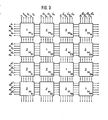
- the display of Figure 3 is the manner of a square (4 x 4) matrix from the two types of modules assembled such that the four slide g onalelem e n th M 11, M 22 'M 33 and M44 of the array of modules of the first type 1 and the remaining twelve elements of the matrix consist of modules of the second type 2.
- the module M 11 is connected to its module M 12 adjacent in the row in such a way that each row line a 1 to a 6 is connected to the same row line of the adjacent module.
- the module M 11 is connected to its module M 21 adjacent in the column in such a way that each column line b 1 to b 6 is connected to the same column line of the adjacent module.
- all modules of each row are M 11 to M 14 ' M 21 to M 24 , M 31 to M 34 and M 41 to M 44 and all modules of each column M 11 to M 41 , M 12 to M 42 , M 13 to M 43 and M 14 to M 44 connected to each other.
- any number of modules can be combined to form a display in an analogous manner be switched.
- the number of leads of the overall display is mn, and the number of diodes that can be controlled with it is mn. (Mn-l), corresponding to the total number of LEDs.
Abstract
Description
- Anzeigeeinheiten (Displays) zur Darstellung von Bildern werden heute unter anderem mit lichtemittierenden Dioden (LED's) ausgeführt. Um eine hinreichend hohe Auflösung zu erreichen, muß eine sehr große Anzahl von Bildpunkten (d. h. z. B. LED's) verwendet werden. In IEEE Transactions on Electron Devices, Vol. ED-26 (1979), Seiten 1182 bis 1186 sind z. B. solche Anzeigeeinheiten beschrieben, die zwischen 6.144 und 38.400 LED's aufweisen. Um diese große Anzahl von LED's getrennt ansteuern zu können, ist eine entsprechend große Anzahl von Zuleitungen notwendig. Wird die Verdrahtung in Art einer Matrix mit Zeilen- und Spaltenzuleitungen ausgeführt, können z. B. mit n Zuleitungen n2/4 LED's angesteuert werden (n gerade).
- Aus Gründen einer wirtschaftlichen Fertigung ist es sinnvoll, Displays mit einer sehr großen Anzahl von LED's in Modulbauweise auszuführen, wie z. B. in Aviation Week & Space Technology, June 18, 1979, Seiten 73 bis 77, beschrieben. So erreicht man, daß einzelne Fehler durch Austausch eines Moduls beseitigt werden können.
- Der Erfindung liegt die Aufgabe zugrunde, ein Display mit LED's anzugeben, das aus Modulen zusammengesetzt ist und das derart verdrahtet ist, daß die Anzahl der zur Ansteuerung des Displays erforderlichen Zuleitungen möglichst gering ist. Diese Aufgabe wird durch die Merkmale des vorliegenden Anspruchs 1 gelöst.
- Das Wesen der Erfindung besteht darin, daß die Anordnung nach der Erfindung aus zwei Typen von Modulen zusammengesetzt ist, daß der erste Modultyp nach einem bestimmten Prinzip verdrahtet ist, daß der zweite Modultyp nach Art einer Matrix verdrahtet ist und daß die Gesamtanordnung wiederum nach dem bestimmten Prinzip verdrahtet ist. Dieses Prinzip sowie der übrige Teil der Erfindung werden im folgenden an einem Ausführungsbeispiel näher erläutert.
- Die Figur 1 zeigt den Aufbau des ersten Moduls am Beispiel eines Moduls mit 6 Zuleitungen und 6 x 5 = 30 Dioden. Als Zuleitungen werden die sechs Zeilenleitungen a1....a6 benutzt. Neben den sechs Zeilenleitungen al....a6 sind bei dem ersten Modultyp der Figur 1 die sechs Spaltenleitungen bl..b6 vorhanden, so daß die Anzahl der Zeilenleitungen gleich der Anzahl der Spaltenleitungen ist. Wie aus der Figur 1 weiter hervorgeht, weist der erste Modultyp eine matrixartige Verdrahtung auf, bei der jede Zeilenleitung mit einer und nur einer Spaltenleitung verbunden ist, und zwar ist a1 mit bl, a2 mit b2, a 3 mit b3, a4 mit b4, a5 mit b5 und a6 mit b6 verbunden. Bei dem ersten Modultyp der Figur 1 ist an jedem Kreuzungspunkt von Zeilen- und Spaltenleitungen, an dem die sich kreuzenden Zeilen- und Spaltenleitungen nicht miteinander verbunden sind, d. h. an allen Kreuzungspunkten mit Ausnahme der Kreuzungspunkte K11, K22' K33' K44, K55 und K66' je eine lichtemittierende Diode vorhanden. Dagegen sind an denjenigen Kreuzungspunkten K11, K22' K 33' K 44' K 55 und K 66 keine LED's vorhanden, an denen die sich kreuzenden Zeilen-und Spaltenleitungen miteinander verdrahtet sind. Der eine Anschluß der LED's des ersten Modultyps der Figur 1 ist jeweils mit der im Kreuzungspunkt vorhandenen Zeilenleitung und der andere Anschluß jeweils mit der im Kreuzungspunkt vorhandenen Spaltenleitung verbunden.
- Die Figur 2 zeigt den zweiten Modultyp, der nach dem bekannten Prinzip der Matrixschaltung aufgebaut ist. Der zweite Modultyp weist ebenso viele Zeilen- und Spaltenleitungen wie der erste Modultyp auf. Beim zweiten Modultyp sind an jedem Kreuzungspunkt von Zeilen- und Spaltenleitungen LED's vorhanden, deren einer Anschluß jeweils mit der im Kreuzungspunkt vorhandenen Zeilenleitunq und deren anderer Anschluß jeweils mit der im Kreuzungspunkt vorhandenen Spaltenleitunq verbunden ist. Beim zweiten Modultyp sind, wie die Figur 2 zeigt, generell keine Zeilenleitungen mit Spaltenleitungen verbunden. Der zweite Modultyp der Figur 2 besitzt je 6 Zeilen- und Spaltenleitungen sowie 36 Dioden.
- Die Figur 3 zeigt die Zusammenschaltung von vier Modulen des ersten und 12 Modulen des zweiten Typs zu einem Display mit in diesem Fall 4 x 30 + 12 x 36 = 552 LED's. Zur Ansteuerung dieses Displays dienen die nach links herausgeführten 24 Leitungen. Das Display der Figur 3 ist nach Art einer quadratischen (4 x 4)-Matrix aus den beiden Modultypen derart zusammengesetzt, daß die vier Diagonalelemente M 11, M22' M33 und M44 der Matrix aus Modulen des ersten Typs 1 und die übrigen zwölf Elemente der Matrix aus Modulen des zweiten Typs 2 bestehen. Der Modul M11 ist mit seinem in der Zeile benachbarten Modul M12 derart verbunden, daß jede Zeilenleitung a1 bis a6 mit der gleichen Zeilenleitung des benachbarten Moduls verbunden ist. Ebenso ist der Modul M11 mit seinem in der Spalte benachbarten Modul M21 derart verbunden, daß jede Spaltenleitung b1 bis b6 mit der gleichen Spaltenleitung des benachbarten Moduls verbunden ist.
- In der gleichen Weise sind alle Module jeder Zeile M11 bis M 14' M21 bis M24, M31 bis M34 und M41 bis M44 und alle Module jeder Spalte M11 bis M41, M12 bis M42, M13 bis M 43 und M 14 bis M44 miteinander verbunden.
- Nach dem in der Figur 3 gezeigten Schema können auf analoge Weise beliebig viele Module zu einem Display zusammengeschaltet werden. Geht man von n Zuleitungen pro Modul aus, so enthält der Modul vom ersten Typ N1 = n.(n-l) LED's und der Modul vom zweiten Typ N2 = n2 LED's. Bildet man aus solchen Modulen ein Display mit je m Modulen in beiden Dimensionen, so enthält dieses m Module vom ersten Typ und m2-m Module vom zweiten Typ. Die Gesamtzahl an LED's ist demnach N = mN1 + (m2-m).N2 = m.n.(n-1) + m.(m-1)n2 = mn.(mn-1). Die Anzahl der Zuleitungen des Gesamtdisplays ist mn, und die Anzahl der hiermit ansteuerbaren Dioden mn.(mn-l), übereinstimmend mit der Gesamtzahl der LED's.
Claims (2)
Applications Claiming Priority (2)
| Application Number | Priority Date | Filing Date | Title |
|---|---|---|---|
| DE3012995 | 1980-04-03 | ||
| DE3012995A DE3012995C2 (de) | 1980-04-03 | 1980-04-03 | Anzeigevorrichtung mit matrixartig angeordneten lichtemittierenden Dioden |
Publications (3)
| Publication Number | Publication Date |
|---|---|
| EP0037916A2 true EP0037916A2 (de) | 1981-10-21 |
| EP0037916A3 EP0037916A3 (en) | 1982-04-14 |
| EP0037916B1 EP0037916B1 (de) | 1985-01-16 |
Family
ID=6099202
Family Applications (1)
| Application Number | Title | Priority Date | Filing Date |
|---|---|---|---|
| EP81102037A Expired EP0037916B1 (de) | 1980-04-03 | 1981-03-19 | Anordnung zur Darstellung von Bildern mit lichtemittierenden Dioden |
Country Status (4)
| Country | Link |
|---|---|
| US (1) | US4365244A (de) |
| EP (1) | EP0037916B1 (de) |
| JP (1) | JPS56158368A (de) |
| DE (1) | DE3012995C2 (de) |
Families Citing this family (31)
| Publication number | Priority date | Publication date | Assignee | Title |
|---|---|---|---|---|
| US4667181A (en) * | 1983-07-15 | 1987-05-19 | Honeywell Inc. | Keyboard data input assembly |
| US5091950A (en) * | 1985-03-18 | 1992-02-25 | Ahmed Moustafa E | Arabic language translating device with pronunciation capability using language pronunciation rules |
| US4654629A (en) * | 1985-07-02 | 1987-03-31 | Pulse Electronics, Inc. | Vehicle marker light |
| DE3682344D1 (de) * | 1985-08-29 | 1991-12-12 | Mitsubishi Electric Corp | Geraet zur erkennung der stelle fehlerhafter lichtemissionselemente in einem grossen bildschirmanzeigesystem. |
| DE3536984A1 (de) * | 1985-10-17 | 1987-04-23 | Blaupunkt Werke Gmbh | Betaetigungsanordnung fuer zwei andruckrollen in einem tonwiedergabegeraet mit reversebetrieb |
| DE3837313A1 (de) * | 1987-11-05 | 1989-05-24 | Eric Cheng | Eine punkt-matrix-led-anzeigeeinheit und eine grosse aus solchen einheiten zusammengesetzte led-anzeige-vorrichtung |
| DE4200879A1 (de) * | 1992-01-15 | 1993-07-29 | Kemo Klaus Kernchen | Leiterplatte zum bestuecken mit leuchtkoerpern |
| US5936599A (en) * | 1995-01-27 | 1999-08-10 | Reymond; Welles | AC powered light emitting diode array circuits for use in traffic signal displays |
| US6526000B1 (en) * | 1995-02-27 | 2003-02-25 | Philip D. Guercio | Pattern display |
| US7066628B2 (en) * | 2001-03-29 | 2006-06-27 | Fiber Optic Designs, Inc. | Jacketed LED assemblies and light strings containing same |
| US7931390B2 (en) * | 1999-02-12 | 2011-04-26 | Fiber Optic Designs, Inc. | Jacketed LED assemblies and light strings containing same |
| US7108392B2 (en) * | 2004-05-04 | 2006-09-19 | Eastman Kodak Company | Tiled flat panel lighting system |
| US7850361B2 (en) | 2004-11-10 | 2010-12-14 | 1 Energy Solutions, Inc. | Removable LED lamp holder |
| US7850362B2 (en) * | 2004-11-10 | 2010-12-14 | 1 Energy Solutions, Inc. | Removable LED lamp holder with socket |
| US8016440B2 (en) | 2005-02-14 | 2011-09-13 | 1 Energy Solutions, Inc. | Interchangeable LED bulbs |
| US20070025109A1 (en) | 2005-07-26 | 2007-02-01 | Yu Jing J | C7, C9 LED bulb and embedded PCB circuit board |
| US7265496B2 (en) * | 2005-09-23 | 2007-09-04 | Fiber Optic Designs, Inc. | Junction circuit for LED lighting chain |
| US7276858B2 (en) | 2005-10-28 | 2007-10-02 | Fiber Optic Designs, Inc. | Decorative lighting string with stacked rectification |
| US7250730B1 (en) * | 2006-01-17 | 2007-07-31 | Fiber Optic Designs, Inc. | Unique lighting string rectification |
| US8083393B2 (en) | 2006-02-09 | 2011-12-27 | 1 Energy Solutions, Inc. | Substantially inseparable LED lamp assembly |
| US20080025024A1 (en) * | 2006-07-31 | 2008-01-31 | Jingjing Yu | Parallel-series led light string |
| US7963670B2 (en) * | 2006-07-31 | 2011-06-21 | 1 Energy Solutions, Inc. | Bypass components in series wired LED light strings |
| US7784993B2 (en) * | 2007-07-13 | 2010-08-31 | 1 Energy Solutions, Inc. | Watertight LED lamp |
| US8376606B2 (en) * | 2008-04-08 | 2013-02-19 | 1 Energy Solutions, Inc. | Water resistant and replaceable LED lamps for light strings |
| US7883261B2 (en) * | 2008-04-08 | 2011-02-08 | 1 Energy Solutions, Inc. | Water-resistant and replaceable LED lamps |
| US8314564B2 (en) | 2008-11-04 | 2012-11-20 | 1 Energy Solutions, Inc. | Capacitive full-wave circuit for LED light strings |
| CN201391793Y (zh) * | 2009-04-20 | 2010-01-27 | 喻北京 | Led灯泡的新型散热结构 |
| US8836224B2 (en) * | 2009-08-26 | 2014-09-16 | 1 Energy Solutions, Inc. | Compact converter plug for LED light strings |
| US11274823B1 (en) | 2016-03-02 | 2022-03-15 | Cooledge Lighting, Inc. | Lighting systems incorporating connections for signal and power transmission |
| US10344954B1 (en) | 2016-03-02 | 2019-07-09 | Cooledge Lighting Inc. | Lighting systems incorporating connections for signal and power transmission |
| US10746358B1 (en) | 2016-03-02 | 2020-08-18 | Cooledge Lighting Inc. | Lighting systems incorporating connections for signal and power transmission |
Citations (2)
| Publication number | Priority date | Publication date | Assignee | Title |
|---|---|---|---|---|
| FR2207620A5 (de) * | 1972-11-22 | 1974-06-14 | Thomson Csf | |
| DE2511678A1 (de) * | 1974-03-21 | 1975-10-02 | Int Standard Electric Corp | Anordnung mit m x n lichtemittierenden dioden und einem zwei-koordinaten-ansteuernetzwerk |
Family Cites Families (1)
| Publication number | Priority date | Publication date | Assignee | Title |
|---|---|---|---|---|
| DE2613647C3 (de) * | 1976-03-31 | 1981-08-27 | Licentia Patent-Verwaltungs-Gmbh, 6000 Frankfurt | Ansteuerschaltung |
-
1980
- 1980-04-03 DE DE3012995A patent/DE3012995C2/de not_active Expired
-
1981
- 1981-03-19 EP EP81102037A patent/EP0037916B1/de not_active Expired
- 1981-03-25 US US06/247,596 patent/US4365244A/en not_active Expired - Fee Related
- 1981-04-03 JP JP4950881A patent/JPS56158368A/ja active Pending
Patent Citations (2)
| Publication number | Priority date | Publication date | Assignee | Title |
|---|---|---|---|---|
| FR2207620A5 (de) * | 1972-11-22 | 1974-06-14 | Thomson Csf | |
| DE2511678A1 (de) * | 1974-03-21 | 1975-10-02 | Int Standard Electric Corp | Anordnung mit m x n lichtemittierenden dioden und einem zwei-koordinaten-ansteuernetzwerk |
Non-Patent Citations (1)
| Title |
|---|
| Elektronik Industrie, Nr. 7/8, 1976 "Ansteuerungen von Leuchtdioden durch TTL-Bausteine" seiten 162 und 163 * |
Also Published As
| Publication number | Publication date |
|---|---|
| DE3012995A1 (de) | 1981-10-08 |
| US4365244A (en) | 1982-12-21 |
| EP0037916B1 (de) | 1985-01-16 |
| JPS56158368A (en) | 1981-12-07 |
| EP0037916A3 (en) | 1982-04-14 |
| DE3012995C2 (de) | 1982-08-26 |
Similar Documents
| Publication | Publication Date | Title |
|---|---|---|
| EP0037916B1 (de) | Anordnung zur Darstellung von Bildern mit lichtemittierenden Dioden | |
| DE102017128738B4 (de) | Anzeigetafel, elektronisches Gerät und Prüfverfahren | |
| DE2916065C2 (de) | Datenverarbeitungseinrichtung | |
| DE3008565A1 (de) | Anordnung zur darstellung von information mit lichtemittierenden dioden | |
| DE2750770A1 (de) | Verfahren und vorrichtung zum darstellen eines symbols auf einem sichtgeraet | |
| DE3404452C2 (de) | ||
| DE2026372A1 (de) | Gerat zur bildlichen Informations ausgabe und Verfahren zur Herstellung desselben | |
| DE60114534T2 (de) | Kondensatorarray-d/a-wandler mit einem temperaturmessgerät-decoder sowie kondensatorray | |
| EP0389744A1 (de) | Anzeigevorrichtung | |
| DE2731717C3 (de) | Flächiges optisches Sichtanzeigefeld | |
| EP0333922A1 (de) | Dreistufiges blockierungsfreies Koppelfeld | |
| DE3431077C2 (de) | ||
| DE3500040A1 (de) | Datenverarbeitungseinrichtung | |
| DE2613647C3 (de) | Ansteuerschaltung | |
| EP0075700A3 (de) | Akustooptischer Lichtablenker mit hoher Auflösung | |
| DE2904914A1 (de) | Elektrisches anzeigegeraet | |
| DE2820269A1 (de) | Leitungszugmuster fuer einen gasentladungsbildschirm | |
| EP0284655A1 (de) | Anzeigevorrichtung | |
| DE4014748C2 (de) | ||
| DE3012687C2 (de) | Modulblock für Stromrichteranlagen | |
| DE2461837C2 (de) | Digitale Anzeigevorrichtung mit einer Punktmatrix | |
| DE3917077A1 (de) | Farbmosaik-anzeigetafel | |
| DE3711255A1 (de) | Anordnung aus led-einheiten | |
| EP0289497B1 (de) | Anzeigevorrichtung | |
| DE69827111T2 (de) | Ansteuervorrichtung einer Flüssigkristall-Anzeigezelle |
Legal Events
| Date | Code | Title | Description |
|---|---|---|---|
| PUAI | Public reference made under article 153(3) epc to a published international application that has entered the european phase |
Free format text: ORIGINAL CODE: 0009012 |
|
| AK | Designated contracting states |
Designated state(s): FR GB IT |
|
| PUAL | Search report despatched |
Free format text: ORIGINAL CODE: 0009013 |
|
| AK | Designated contracting states |
Designated state(s): FR GB IT |
|
| 17P | Request for examination filed |
Effective date: 19820406 |
|
| RAP1 | Party data changed (applicant data changed or rights of an application transferred) |
Owner name: TELEFUNKEN ELECTRONIC GMBH |
|
| ITF | It: translation for a ep patent filed |
Owner name: BARZANO' E ZANARDO MILANO S.P.A. |
|
| GRAA | (expected) grant |
Free format text: ORIGINAL CODE: 0009210 |
|
| AK | Designated contracting states |
Designated state(s): FR GB IT |
|
| ET | Fr: translation filed | ||
| PLBE | No opposition filed within time limit |
Free format text: ORIGINAL CODE: 0009261 |
|
| STAA | Information on the status of an ep patent application or granted ep patent |
Free format text: STATUS: NO OPPOSITION FILED WITHIN TIME LIMIT |
|
| 26N | No opposition filed | ||
| GBPC | Gb: european patent ceased through non-payment of renewal fee | ||
| PG25 | Lapsed in a contracting state [announced via postgrant information from national office to epo] |
Ref country code: FR Free format text: LAPSE BECAUSE OF NON-PAYMENT OF DUE FEES Effective date: 19871130 |
|
| REG | Reference to a national code |
Ref country code: FR Ref legal event code: ST |
|
| PG25 | Lapsed in a contracting state [announced via postgrant information from national office to epo] |
Ref country code: GB Effective date: 19881118 |